SLAC–PUB–7752
February 1998
LATTICE AND COMPENSATION SCHEMES
FOR THE PEP-II INTERACTION REGION
***Work supported by Department of
Energy contract DE–AC03–76SF00515.
Y. Nosochkov, Y. Cai, M.H.R. Donald, J. Irwin
D.M. Ritson, J. Seeman, M. Sullivan
Stanford Linear Accelerator Center, Stanford University, Stanford, CA 94309
Abstract
The PEP-II interaction region is designed to accommodate asymmetric beam energies, head-on collisions, small bunch spacing and to provide low for high luminosity. Local correction schemes are implemented to compensate non-linear chromaticity from the IP doublets as well as coupling, orbit and focusing effects from the 6 Tm asymmetric detector solenoid. The main IR optics features and local correction schemes are presented. MAD[1] code is used for the optics calculations.
Talk presented at
Advanced ICFA Workshop on Beam Dynamics Issues for e+e-
Factories
LNF–INFN, Frascati, Italy
October 20–October 25, 1997
1 IR optics
In the PEP-II asymmetric collider the High Energy Ring (HER) and the Low Energy Ring (LER) consist of 6 arcs and 6 straight sections[2, 3]. The two rings are vertically separated except at the interaction point (IP) where the 9 GeV electron and 3.1 GeV positron beams are brought into collision.
The PEP-II interaction region (IR) optics has to meet the requirement for high luminosity, provide adequate dynamic aperture and satisfy geometric constraints. The following IR conditions are applied to attain the design luminosity: low IP beta ( m), zero IP dispersion, and head-on collisions. Head-on collisions minimize the effect of synchro-betatron resonances, though they require a more complicated separation scheme compared to a crossing angle collision. Maximizing dynamic aperture requires: compensation of the 6 Tm detector solenoid, compensation of non-linear chromaticity produced by the IP doublets, matching IR optics to the arcs, and maximizing beam separation at parasitic crossing points. Geometric constraints include: separation of two ring components after collision, providing 0.89 m vertical separation between the LER and HER after the IP, matching the IR trajectory to the arcs, and fitting the IR components into the existing tunnel.
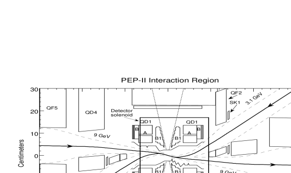
The PEP-II IR optics has the following symmetry with respect to the IP: symmetric longitudinal positions of the ring components, symmetric quadrupole focusing, symmetric vertical bending, and antisymmetric horizontal bending. The IR focusing symmetry maintains the ring symmetry with respect to the IP and allows the IR sextupole correction to be symmetric. The nominal values at the IP for the design luminosity are 0.5 m/1.5 cm for the LER and 0.667 m/2 cm for the HER. Because of the asymmetric beam energies the IR optics is essentially independent for the two rings which requires a fast separation of the two ring components after the IP. The first magnets near the collision point are horizontal separation bends B1 placed at m from the IP. The asymmetry in beam energies is just enough to produce sufficient beam separation in the B1 for a zero crossing angle. To minimize the size of the divergent beams after the IP the LER functions are focused with the quadrupole doublet QD1, QF2 placed next to the B1 (see Fig.1). The B1 and QD1 are the only magnets shared by the two rings. The QD1 produces helpful vertical focusing on the HER beam as well, and the focusing is completed with a separate HER doublet QD4, QF5. Besides the field gradient the QD1, QF2, QD4 magnets have a vertical dipole field on the reference orbit of one or the other beam to help the horizontal beam separation. As a result, the two beams are sufficiently separated at the first two parasitic collisions: mm at m and mm at m. The QF2, QD4, QF5 are septum magnets to make easier separation of the LER and HER components.
The antisymmetric horizontal bending in the IR allows us to minimize the IR trajectory excursions by adjustment of the horizontal orbit slope at the IP with respect to the tunnel. The optimized value of this angle is -16.9 mrad. The vertical separation between the rings is achieved with a pair of LER vertical bends BV1,2 on either side of the IP. The bends are placed apart in -phase and have identical to cancel vertical dispersion. One complication of the IR geometry in the LER is the interleaved horizontal and vertical bends which cause a tilt of the beam eigenplanes with respect to the mid-plane. Once the IR magnets are properly aligned to close the ring circumference, the above leads to a small betatron coupling which has to be canceled.
Besides the vertical bends the IR in the LER accommodates a pair of local sextupoles to correct -chromaticity generated by the IP doublet. This requires a transformation between the sextupoles, a minimum -phase advance between the sextupoles and the doublet, a high ratio and a non-zero dispersion at the sextupoles. A similar requirement for a high or ratio is applied to the semi-local sextupoles placed in the nearby arcs where local bumps were created. One half of the IR and the adjacent arc in the LER is shown in Fig.2 where the IP is at . The HER has similar bumps in the arcs near the IR for the semi-local sextupoles, but the IR optics is much simpler compared to the LER.

2 Local and semi-local chromatic correction
In a low optics the functions at the IP doublets attain very high values and the doublet quads are stronger than other ring quadrupoles. This results in two single sources of large chromaticity. In the PEP-II lattice the two IP doublets make about to of the ring linear chromaticity. For such a large chromatic perturbation the non-linear part becomes significant. Moreover, the non-linear chromaticity from the two doublets amplify each other, while in the rest of the ring it tends to cancel out because of periodicity or special phase advance such as per cell. The chromatic effect of the IP doublets can significantly reduce the momentum dependent dynamic aperture and requires special correction. We refer to a local compensation when correcting sextupoles are placed close to the IP doublet, and to a semi-local correction if they are located farther from the doublet in betatron phase.
The method to use the correcting sextupoles is: 1) to place them in a nearby dispersive region with the phase advance in the corresponding plane of from the doublet, where is a fine adjustment for optimum correction; 2) to use pairs of identical sextupoles separated by a transformation to cancel sextupole geometric aberrations; 3) to have large or ratio at the sextupoles for orthogonal and correction and to minimize sextupole strengths; 4) to have no other sextupoles within each sextupole pair to minimize octupole-like tune shift with amplitude. It is advantageous to place sextupoles as close as possible to the corrected doublet to avoid a disturbing effect by the magnets in the middle. The chromatic effects to be minimized are tune shift with momentum; variation of function with momentum at IP, injection point and RF cavities; higher order dispersion at IP and RF cavities. It is also necessary to keep to a minimum the sextupole geometric aberrations such as tune shift with amplitude and resonance driving terms. For a better correction all ring sextupole families have to be optimized. Fig.3 shows how chromatic beta perturbation produced by a doublet is compensated by the opposite beta wave from a pair of sextupoles.
In the HER the cells allow us to place 2 ( and ) semi-local non-interleaved sextupole pairs in each arc adjacent to the IR. A local bump was created in these arcs to increase ratio at the sextupoles from 3 to 13. The rest of the HER is corrected with standard two family interleaved sextupoles SF, SD placed in the other 4 arcs. In the LER the correction scheme per half IR includes one local pair of -sextupoles placed next to the IP doublet in a section with non-zero dispersion and high ratio, and 4 semi-local non-interleaved sextupole pairs in the arc near IR (see Fig.2). The cells in the LER allow more room for the sextupole pairs compared to the HER. A bump in the two arcs increases the ratio at the sextupoles from 5.8 to 14. The rest of the LER has 4 non-interleaved pairs of SF1, SF2 or SD1, SD2 sextupoles per arc to correct linear chromaticity. In both rings the correction scheme is symmetric about IP. The IR local chromatic compensation significantly reduces momentum dependent tune shift and variation of .
3 Solenoid compensation
The PEP-II detector solenoid has a significant effect on the beam optics. The integrated solenoid field is 6.07 Tm which rotates the LER beam eigenplanes by . The most part of the solenoid field is located within 4 m near IP with the maximum field of 1.5 T. With the fringe field included the solenoid length extends over 6 m. The solenoid field profile is shown in Fig.4. Other complications are: 1) the solenoid center is placed 37 cm from the IP in the direction of the HER beam; 2) the solenoid overlaps the B1, QD1 and QF2 magnets on both sides of the IP, hence the fields are superimposed; 3) neither beam is parallel to the solenoid axis, and the solenoid is horizontally tilted with respect to the beam orbit at the IP (see Fig.1). The solenoid effects are: 1) coupling of and betatron motion; 2) beam focusing in both planes; 3) vertical orbit and dispersion caused by the solenoid tilt, and horizontal orbit and dispersion induced by the coupling.

To model the superposition of the solenoid, quadrupole and dipole fields in the optics and tracking codes each of the B1, QD1 and QF2 magnets have been replaced by a combination of thin lenses with thick solenoid pieces between them. In the edge model the solenoid field is held constant, the solenoid pieces are aligned along the beam and the vertical orbit from the solenoid tilt is simulated with a set of thin vertical kicks. In the edge model the field is a piece-wise function of the longitudinal position, and each solenoid piece is properly aligned with respect to the beam trajectory. The field model is illustrated in Fig.5.
The solenoid correction requirements include: 1) uncoupled and betatron motion at the IP; 2) no residual orbit or dispersion at the IP; 3) nominal function at the IP; 4) no optics perturbation outside the IR. With the asymmetric solenoid this implies local and independent correction on the left and right sides of the IP. In particular, the transfer matrix from the arcs to the IP must be uncoupled and matched independently on each side of the IR.
The PEP-II design makes it difficult to use compensating solenoids near the IP to correct coupling from the detector solenoid, therefore we have adopted a skew quadrupole correction system[4]. The correction scheme per each half IR consists of: 1) 4 skew quadrupoles to uncouple the transfer matrix between the arcs and the IP; 2) 2 skew quadrupoles placed in dispersive regions to correct vertical dispersion and slope at the IP; 3) 2 horizontal and 2 vertical orbit correctors to correct the orbit at the IP; 4) 8 quadrupoles or more to match twiss functions and horizontal dispersion , at the IP. The optimum phases for the 4 skew quadrupoles to correct coupling are ( ) from the IP. The optimum phases for orbit and dispersion correctors are 0 and ( ) from the IP in the corresponding plane. The following adjustments helped to minimize the orbit excursions near the IP: 1) solenoid horizontal tilt angle of 20.4 mrad with respect to the beam trajectory at the IP; 2) vertical displacement of the IP by 3.7 mm; 3) vertical displacement of QF2, QD4 quadrupoles by a few mm to help orbit correction.
In the existing lattice it is not always possible to find the absolutely optimum positions for all correctors, therefore the coupling, orbit, dispersion and function corrections are not completely independent and for exact correction require simultaneous adjustment of all the above correctors. However, for a small variation of individual optics parameters a smaller number of correctors can be used leaving practically negligible residual perturbation.
References
- [1] H. Grote, F.C. Iselin (CERN). CERN/SL/90-13 (AP) rev.4, August 1994.
- [2] M.H.R. Donald et al. SLAC-PUB-95-6873, April 1995.
- [3] Y. Cai et al. SLAC-PUB-95-6868, May 1995.
- [4] Y. Nosochkov et al. SLAC-PUB-95-6890, May 1995.