SLAC–PUB–8870
June 2001
Study of Low Straight Section in SPEAR 3 111Work supported by Department of Energy contract DE–AC03–76SF00515.
Y. Nosochkov, J. Corbett and T. Rabedeau
Stanford Linear Accelerator Center, Stanford University,
Stanford, CA 94309
Abstract
The SPEAR 3 light source [1] has two 7.6 m straight sections one of which is available for new insertion devices (ID). By reducing the vertical function at the center of the straight from 9.8 m to 1.5 m, the beam size can be decreased from 44 m to 17 m to reduce the ID gap, but the ID length may be limited by the increased variation in the ID. Alternatively, a “double waist” optics with two symmetric low locations and a chicane may be considered to implement two IDs. In this paper, we discuss the low optics, effects on the beam dynamic aperture, and the ID parameters needed to maximize photon flux density and brightness while maintaining electron beam lifetime.
Presented at the 2001 Particle Accelerator Conference
(PAC 2001)
Chicago, Illinois, June 18–22, 2001
STUDY OF LOW STRAIGHT SECTION IN SPEAR 3 ††thanks: Work sponsored in part by DOE Contract DE-AC03-76SF00515 and the Office of Basic Energy Sciences, Division of Chemical Sciences.
Abstract
The SPEAR 3 light source [1] has two 7.6 m straight sections one of which is available for new insertion devices (ID). By reducing the vertical function at the center of the straight from 9.8 m to 1.5 m, the beam size can be decreased from 44 m to 17 m to reduce the ID gap, but the ID length may be limited by the increased variation in the ID. Alternatively, a “double waist” optics with two symmetric low locations and a chicane may be considered to implement two IDs. In this paper, we discuss the low optics, effects on the beam dynamic aperture, and the ID parameters needed to maximize photon flux density and brightness while maintaining electron beam lifetime.
1 INTRODUCTION
The SPEAR 3 design optics consists of two periodic arcs separated by the East and West matching cells [2]. Intended locations for the insertion devices in the arcs are the twelve 3.1 m drift sections between the 14 arc cells and four 4.8 m drifts at the arc ends. At present, the matching cells (MC) have identical symmetric optics with a 7.6 m drift at the center of MC and phase advance [] per cell. The East 7.6 m drift is available for the new IDs, and the West MC will contain the RF accelerating cavities.
The photon flux density and brightness in the insertion devices depend on the electron beam size and, hence, functions at the IDs. At present, the values are m at the arc drift sections, and m at the center of 7.6 m drifts. For the SPEAR 3 design vertical emittance of nm at 3 GeV, the vertical beam size is 31 and 44 m at the ID locations in the arcs and MCs, respectively. The beam size and the ID gap can be reduced by decreasing the at ID, but this will increase the beam divergence and variation of in the ID. For a better ID performance, a large variation in the insertion device should be avoided by limiting the ID length or the minimum value of . The value is also limited by the acceptable size of dynamic aperture and beam lifetime.
In this report, we discuss the low options for the 7.6 m drift in the East MC. The West MC was maintained close to nominal in most of this study. The optics and dynamic aperture calculations were done using MAD [3] and LEGO [4] codes, respectively.
The present SPEAR 3 optics has been well optimized for a maximum dynamic aperture. To maintain the current lattice properties, the following requirements were used for the low beta modifications:
-
•
Matched optics using local quadrupoles.
-
•
Minimal change of the local phase advance.
-
•
Minimal increase of maximum functions.
-
•
Realistic quadrupole strengths.
In addition, we tried to keep equal or close phase advance in the East and West MCs and limit the sextupole strengths, since the stronger sextupoles and ring optical asymmetry may enhance resonance effects and reduce dynamic aperture.
The nominal lattice functions in the MC are shown in Fig. 1, where the 7.6 m drift is at center. The corresponding dynamic aperture without ID effects is shown in Fig. 2, where the solid and dash lines are for the nominal and 3% off-energy particles, respectively. The dynamic aperture simulations included a full set of magnet errors and machine correction for six random error settings.


2 SINGLE LOW IN THE MC
Several options for a matching cell with single low were analyzed as listed in Table 1, where is at the MC center, is the MC phase advance, the ring natural chromaticity, and the K-values of global sextupoles.
| [m] | ||||
|---|---|---|---|---|
| East | West | East | West | |
| 1 | 1.0 / 4.41 | 9.78 / 5.08 | 1.60 / 0.90 | 1.60 / 0.80 |
| 2 | 1.0 / 3.77 | 9.78 / 6.49 | 1.56 / 0.96 | 1.56 / 0.96 |
| 3 | 1.0 / 4.35 | 9.77 / 5.04 | 1.60 / 0.90 | 1.60 / 0.90 |
| 4 | 1.5 / 5.25 | 9.00 / 5.09 | 1.60 / 0.87 | 1.60 / 0.87 |
| 5 | 2.0 / 6.04 | 9.17 / 5.09 | 1.60 / 0.84 | 1.60 / 0.84 |
| 1 | -22.20 / -15.35 | 31.43 / -37.96 |
|---|---|---|
| 2 | -22.67 / -15.70 | 31.21 / -37.30 |
| 3 | -22.26 / -15.51 | 31.46 / -37.79 |
| 4 | -22.03 / -15.19 | 31.09 / -37.41 |
| 5 | -21.90 / -15.03 | 30.85 / -37.26 |
The low optics in the East MC was matched using five local quadrupole families while the West MC was maintained close to the nominal. For low peaks and chromaticity, the MC phase advance was slightly varied. The arc phase was adjusted accordingly to keep the working tune at .
Comparison of the three m options showed a larger dynamic aperture in case 3. It indicates that the preferred optical conditions are close to the nominal phase advance, equal phase advance in the two MCs, low chromaticity and weak sextupoles. Note that low naturally increases the MC vertical phase advance since .
Cases 4,5 with and 2 m were designed similar to case 3. In comparison, the lower requires stronger focusing and larger quadrupole strengths as listed in Table 2. Consequently, the lower leads to larger peaks in the MC, higher chromaticity and stronger sextupoles, and reduced dynamic aperture. At present, the QDXE, QFXE design strengths are limited at , therefore optics with m would require an upgrade of these magnets.
| [m] | 1.0 (c.3) | 1.5 | 2.0 |
|---|---|---|---|
| QDXE | -1.9269 | -1.6027 | -1.3254 |
| QFXE | 1.8308 | 1.7695 | 1.6880 |
| QDYE | -0.8003 | -0.9760 | -1.0481 |
| QDZE | -0.6667 | -0.7032 | -0.7245 |
| QFZE | 1.3458 | 1.4110 | 1.4512 |
Maintaining sufficient aperture for horizontal injection and beam lifetime with Touschek effects requires a large horizontal dynamic aperture with up to 3% energy errors. LEGO simulations with machine errors, but without ID effects, estimate the horizontal dynamic aperture near 16 mm for m, and 17 mm for and 2 m, compared to the nominal 18-20 mm aperture. This aperture may be sufficient even with the ID effects included which will reduce it by 1-2 mm. For a conservative design, we consider an option with m. The MC optics and dynamic aperture in this case are shown in Fig. 3 and 4.


It had been shown that the SPEAR 3 horizontal emittance can be reduced by allowing a small dispersion cm in the arc drifts [5]. The required dispersion was obtained by slightly mismatching the arc achromats and appropriate adjustment of the matching cells. In this low study, we verified dynamic aperture for and 10 cm in the arc drifts. LEGO simulations without ID effects showed that at m the horizontal dynamic aperture is 15-16 mm at cm, and 13 mm at 10 cm dispersion. We conclude that dispersion up to 5 cm may be used to reduce the horizontal emittance from 18.5 to 14.6 nm.
The low function increases beam divergence and variation in the ID and may limit the ID length. At distance from the waist: , where is at the waist. For example, for variation below 100% and the waist at ID center, the half ID length has to be less than .
3 DOUBLE LOW IN THE MC
The 7.6 m straight section in the matching cell can be upgraded to have two low locations for two IDs. A double waist optics can be obtained using an extra quadrupole triplet at center of the straight. An example of such optics with two symmetric m locations is shown in Fig. 5, where the space available for each ID is about 2 m and the six local quadrupole families are adjusted to keep the MC matched.

The separation of the two ID beam lines can be done using a four bend horizontal chicane. We investigated symmetric and anti-symmetric chicane schemes with 25 cm dipoles placed symmetrically around the waists as shown in Fig. 5. In the symmetric scheme, the bending angles in the four dipoles were [-10,+10,+10,-10] mrad which produce 24.7 mm closed orbit bump and 20 mrad angle between the beam lines. In the anti-symmetric scheme, the bending angles were [-8,+25.7,-25.7,+8] mrad to generate two mm bumps and parallel ID beam lines with horizontal separation of 57 mm.
The chicane bends generate additional dispersion in the MC. We found that with the symmetric chicane this dispersion can be locally compensated by slightly mismatching the MC achromats. In the anti-symmetric scheme, the dispersion could not be fully compensated using local quadrupoles, but the residual dispersion in the ring is below 4 cm which is not a problem for the IDs. This dispersion has only minor reduction effect on the emittance. The anti-symmetric double waist optics is shown in Fig. 5.
The double optics further increases the vertical phase advance in the MC. Similar to the single optics, the has to be kept close to the nominal value for a better dynamic aperture. For realistic magnet strengths and matched optics, the vertical phase advance was set at 1.1 [] as compared to the nominal 0.8 []. The MC sextupole strengths were optimized for larger dynamic aperture.
LEGO simulations showed a larger dynamic aperture in the anti-symmetric scheme as shown in Fig. 6. This aperture may be sufficient for the beam operation, but more study is required for the design of ID beam lines.
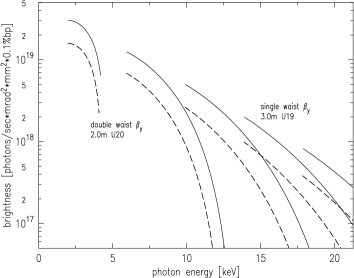
4 UNDULATOR PERFORMANCE
The primary motivation for reducing in the matching cells is to enhance hard x-ray brightness from small gap undulators. To evaluate the potential performance of small gap undulators in the MC, a rough examination of suitable undulator parameters was undertaken using the XTC routine of the XOP software suite [6]. Tuning curve simulations for hybrid, planar undulators in the absence of field errors are shown in Fig. 7 for the ID parameters listed in Table 3. The curves depict the fundamental and odd harmonics through the 9th order. For the high brightness hard x-ray beams, the undulator parameters were selected to provide reasonable tuning curve overlap in the keV regime without concern for the coverage gap between the first and third harmonics for keV. The magnet gaps used in the simulations preserve reasonable beam lifetime, though somewhat improved performance at high energies could be obtained using smaller gaps.

| waist | gap | period | length | |
|---|---|---|---|---|
| [m] | [mm] | [mm] | [m] | |
| single | 5.25 / 1.5 | 5.0 | 19.0 | 3.0 |
| double | 8.0 / 2.0 | 6.0 | 20.0 | 2.0 |
5 CONCLUSION
We conclude that the SPEAR 3 design permits single or double low optics in the matching cell 7.6 m drift with as low as 1 m. Dynamic aperture for this optics seems to be acceptable for beam operation.
References
- [1] R. Hettel et al., “Design of the SPEAR 3 Light Source,” EPAC 2000, Vienna, June 2000.
- [2] J. Corbett et al., SLAC–PUB–7882, July 1998.
- [3] The MAD Home Page, http://wwwslap.cern.ch/mad/.
- [4] Y. Cai et al., SLAC–PUB–7642, August 1997.
- [5] J. Safranek, “Non-Zero Dispersion in the SPEAR 3 Straights,” February 1998, unpublished.
- [6] M. Sanchez del Rio, et al., SPIE, 3152, p. 148 (1997).