Ultra-low threshold CW Triply Resonant OPO in the near infrared using Periodically Poled Lithium Niobate
Abstract
We have operated a CW triply resonant OPO using a PPLN crystal pumped by a Nd:YAG laser at 1.06 and generating signal and idler modes in the 2-2.3 range. The OPO was operated stably in single mode operation over large periods of time with a pump threshold as low as 500 .
1 Introduction
Periodically poled materials have opened the possibility of designing more efficient Optical Parametric Oscillators. In particular, they provide large nonlinearities in frequency ranges in which usual crystals using birefringence for phase matching were not very efficient. This was the case for example for the parametric generation of signal and idler fields in the 2 - 2.3 region using a Nd:YAG laser as a pump, where only critically phase matched crystals were available : parametric oscillation was reported in this region only with high peak power pulsed Nd:YAG lasers [1, 2], or in the CW regime using ultra-low loss devices with internal reflection [3]. The availability of periodically poled LiNbO3 crystals has opened the way to very promising new devices in this frequency range, which is of particular interest for molecular spectroscopy and LIDAR applications [4]. Let us quote in particular a pulsed singly resonant OPO [5, 6] with broad tunability and significant output power, and a pump-enhanced singly resonant single mode CW OPO, with a minimum threshold well below 1 [7]. We describe here another device based on a PPLN crystal, namely a Nd:YAG laser pumped, signal-idler-pump triply resonant CW OPO working in the region 2-2.3 , which has a threshold in the range.
2 Description of the OPO
The nonlinear crystal is a PPLN from Crystal Technology, with 8 different poling periods ranging from 30 to 31.2 . It is inserted in a 65 mm long linear optical cavity closed by two mirrors having a radius of curvature of 30 . This ensures mode waist sizes at the center of the crystal of 36 at 1.06 and 51 at 2 , large enough to prevent any losses when the beam crosses the 500 high end faces of the crystal.
The pump source is made of a CW monolithic diode-pumped Nd:YAG laser (Lightwave 126-1064-700) spatially and frequency filtered using a resonant Fabry-Perot cavity. This filtering was necessary to ensure that the pump laser is shot-noise limited above 5 for quantum noise reduction measurements [8] but the OPO could also be operated without it. A pair of lenses ( and ) assures a mode matching of the pump beam to the OPO cavity of 97 %. The OPO cavity input mirror has an intensity reflection coefficient of 87% at 1.06 and 99.8% in the range 2-2.2 . The output mirror has a reflection coefficient of 99.8 at 1.06 and roughly 99% in the range 2-2.2 . The end faces of the crystal are anti-reflection coated at both wavelengths (residual reflection coefficient : 0.6% at 1.06 and 0.5% in the range 2-2.2 ). This gives theoretical cavity finesses of roughly 37 at the pump frequency and 200 at 2.2 . The experimental measurement of the finesse at 1.06 in conditions where OPO operation was not present gives a finesse in good agreement with the theoretical result. It is important to note that our OPO was not designed to maximize the signal-idler output but rather to optimize the pump squeezing experiment [9], which requires low pump to signal-idler energy transfers.
3 OPO oscillation characteristics
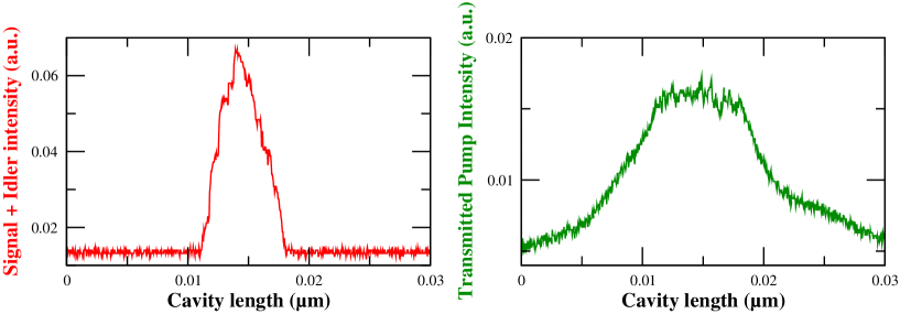
Figure 1 shows a typical recording of the intensity of light transmitted through the output mirror respectively at 1.06 and around 2 , as a function of time when the cavity length is modified via a piezoelectric ceramic. Generation of infrared light and a strong pump depletion are observed when the cavity length is close to a resonance with the pump frequency. When one uses the 31.1 period poled region, and a crystal heated at 160∘, the oscillation threshold was measured to be below 500 . This ultra-low threshold was limited in cavity length by the pump resonance and was obtained within 0.5 around the degeneracy temperature. We have also obtained OPO oscillation with a period of 30.95 . In that case, close to the corresponding frequency degeneracy temperature (), the threshold was similar. The other paths had very large frequency degeneracy temperatures (above 220∘) which made their use unpractical.
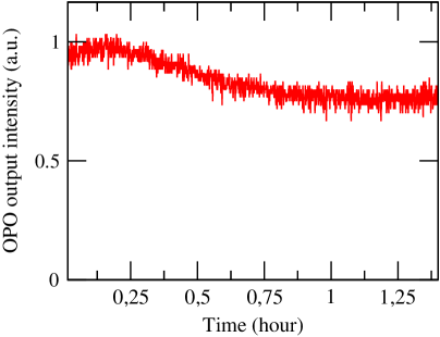
The infrared signal can be used in a feedback loop to stabilize the intensity of the OPO. The error signal is obtained using a lock-in amplifier and a modulation of the cavity length at a frequency of 1 . With this technique, the output power residual fluctuations are of the order of a few %. We have been able to keep the cavity locked for a period over 1 hour (fig. 2). The power drift was mostly due to a slow temperature drift of the crystal.
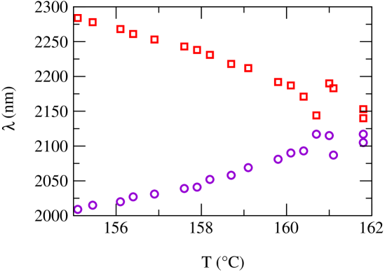
Figure 3 gives the measured wavelengths of the signal and idler beams as a function of the crystal temperature when the cavity length is dithered close to a pump-cavity resonance. The well known parabolic shape, characteristics of a type I crystal is obtained, with some extra points lying outside the parabola, especially close to the degeneracy point. The same kind of behavior has been already observed in CW OPOs [10]. The explanation is simple : the parabola gives the locus of perfect phase matching as a function of temperature. The OPO may oscillate at wavelengths that lie in the neighborhood of this curve, within a range given by the gain bandwidth, and at specific values imposed by the signal idler double resonance conditions. As already observed [10], this range is especially broad in the vicinity of the degeneracy point. As the cavity length is scanned across pump resonance, the signal and idler modes frequencies emitted change on a very short range while, for a given length, only one pair of signal/idler modes is generated. A precise check of the single mode character of our OPO was made using a high finesse Fabry-Perot around 2 showing mode hops as the OPO cavity length was scanned, the beat note frequency change between mode hops corresponding to the free spectral range of the OPO cavity. It is important to note that close to degeneracy, as long as the pump intensity is sufficient (i.e. within a pump resonance), there is oscillation at any cavity length. This is in contrast with the case of the type-II OPO where oscillation takes place only in small cavity lengths intervals around lengths corresponding to the exact double resonance condition.
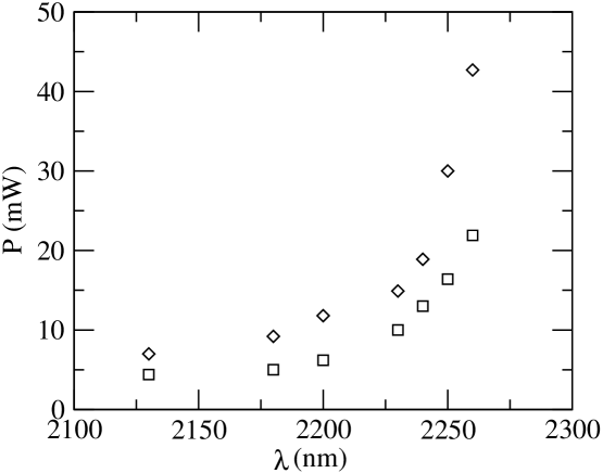
The upper curve of Figure 4 gives the experimental value of the OPO oscillation threshold, which is equal to 5 close to degeneracy, and increases to 40 for the signal-idler couple (2.25m-2.00m ). The lower curve gives the theoretical expectation, corresponding to the formula [11]:
| (1) |
where are the intensity transmission and loss coefficients for the pump signal and idler modes respectively, and the effective nonlinear coefficient taking into account in particular the three interacting Gaussian modes geometrical overlap. The ratio between the theory and the experiment is roughly constant, of the order of 0.4, which can be considered as satisfactory, in view of the experimental calibration uncertainties, and of the various simplifying assumptions leading to the previous formula (mainly the fact that there is no phase shift accumulated between the two nonlinear interactions occurring in one round trip in the linear cavity which is well known to increase threshold [12]). The increase in the threshold value when one is far from the degeneracy point arises from the higher transmission and loss factor at these wavelengths, due to the fact that the mirror reflection curves have been designed to optimize the OPO close to degeneracy.
This minimum threshold of 5 was observed in a first series of experiments during which a spectrometer in the 2 range was available. We have thus obtained the gross dependence of the threshold with temperature. In a second series of experiments, we have improved the set-up by adding a filtering cavity for the pump in order to improve mode-matching and thus the oscillation threshold. Figure 5 shows the variation of the output power as a function of pump power close to degeneracy in this improved version of the setup. A rather satisfactory agreement between the experimental data and the theoretical formula (in which the experimental value of the threshold has been used) is obtained :
| (2) |
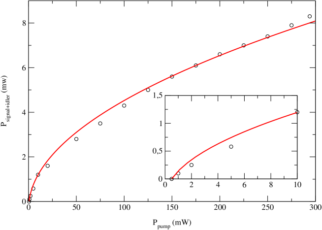
The maximum output power for a 300 pump and in the conditions of minimum threshold is of 8 . The low conversion efficiency to the signal and idler modes is of course due to the fact that the transmission of the output mirror is smaller than the losses (mainly on the anti-reflection coatings) for these modes. This configuration has been chosen to minimize the threshold, and not to optimize the conversion efficiency.
4 Conclusion
We have demonstrated stable operation of a triply resonant OPO with an ultra-low threshold below 1 close to degeneracy using periodically-poled Lithium Niobate pumped by a Nd:YAG laser. Farther from degeneracy, the signal-idler frequencies follow the expected parabola-shaped curve. The ultra low threshold obtained allows operation well above threshold even for moderate pump powers far from the saturation of photodiodes. This has enabled us to demonstrate quantum noise reduction on the pump laser using periodically-poled materials [8].
References
- [1] R. Herbst, R. Fleming, R. Byer Applied Physics Letters 25, 520 (1974)
- [2] J. Lin, J. Montgomery, Optics Commun. 75, 315 (1990)
- [3] D. Serkland, R. Eckardt, R. Byer, Optics Letters 19, 1046 (1994)
- [4] R. Frehlich, Journal of Atmospheric and Oceanic Technology, 12 (1995)
- [5] L. Myers, R. Eckardt, M. Fejer, R. Byer, W. Bosenberg, Optics Letters 21, 591 (1996)
- [6] W. Bosenberg, A. Drobshoff, J. Alexander, L. Myers, R. Byer, Optics Letters 21, 1336 (1996)
- [7] K.-J. Boller,, M.E. Klein, D.-H. Lee, P. Gross, H. Ridderbusch, M.A. Tremont, A. Robertson, J.-P. Meyn, R. Wallenstein, CLEO oral communication, Nice (sept. 200)
- [8] K.S. Zhang, T. Coudreau, M. Martinelli, A. Maître, C. Fabre, to be published in Phys. Rev. A
- [9] K. Kasai, JiangRui Gao, C. Fabre, Europhys. Lett. 40, 25 (1997)
- [10] R. Eckardt, C. Nabor, W. Kozlovsky, R. Byer J. Opt. Soc. Am. B8, 646 (1991)
- [11] C. Fabre, in Advanced Photonic with Second-order Optically Nonlinear Processes, A.D. Boardman et al. (eds.), Kluwer Academic Publishers (1999)
- [12] T. Debuisschert, A. Sizmann, E. Giacobino, C. Fabre J. Opt. Soc. Am. B10, 1668 (1993)