Test Beams and Polarized Fixed Target Beams at the NLC
Abstract
A conceptual program to use NLC beams for test beams and fixed target physics is described. Primary undisrupted polarized beams would be the most simple to use, but for NLC, the disrupted beams are of good enough quality that they could also be used, after collimation of the low energy tails, for test beams and fixed target physics. Pertinent issues are: what is the compelling physics, what are the requirements on beams and running time, and what is the impact on colliding beam physics running. A list of physics topics is given; one topic (Møller Scattering) is treated in more depth.
I Introduction
During the last 10 years, colliding beam physics with the SLC/SLD was SLAC’s main program. During most of the SLC colliding beam running, SLAC was also engaged in a highly successful fixed target program. The main emphasis was on the spin content of the nucleon (E-142 slace142 and E-143 slace143 at 30 GeV, and E-154 slace154 and E-155 slace155 at 50 GeV), but other fundamental experiments like E-144 also ran slace144 . Typically two months per year were set aside from the main program. Test beamscavalli93 ) were used parasitically for smaller experiments (E-146, LPM ) and for detector development, in particular GLAST glast96 .
This report discusses the possibilities for using the NLC nlczdr primary electron beam for fixed target physics or to produce secondary hadron test beams. While dedicated operation of a fixed target program is obviously the most efficient, we will assume that test beam or fixed target running is done in parallel with colliding beam physics. Other design conditions are that there must be permitted access to the fixed target and test beam experimental building during colliding beam operation, there should be useful hadron and electron yields up to about 80% of the primary beam energy, and a single beam transport line and experimental area can be used for both tests and fixed target running.
Figure 1 shows possible locations of such test beam and fixed target beam facilities: they could be at the end of the electron linac (dedicated running only), or behind either IP following the NLC extraction line. The scheme shown is based on the current NLC design of a low energy IR (up to 500 GeV center of mass (cms), i.e., 250 GeV per beam), and a high energy IR (up to 1 TeV cms) expandable to higher energies. To keep the option for multi-TeV beams open, the beam path to the high energy IR has minimal bends; this requires that the linacs have a small angle of mrad between them to enable the outgoing bunches to be separated from the incoming beam.
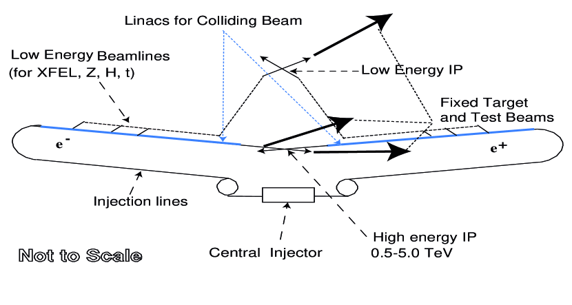
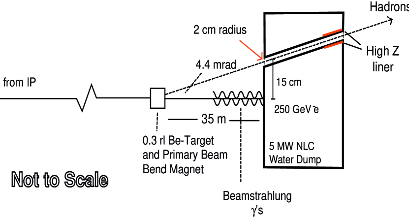
Figure 2 shows a schematic layout of the NLC low energy IR extraction line, including the 5 MW water beam dump, and the proposed test beam and fixed target take-off. For colliding beam physics the beam dump intercepts both the disrupted, primary electrons and the beamstrahlung ’s. For test beams, a 0.3 radiation length Be target is placed in the disrupted beam for production of secondary e-, , K-, p̄ (or their anti-particles). To extract the primary beam for fixed target physics, a dipole is placed at the location of the Be target to bend the beam into the secondary transport line. The dipole aperture must be large enough so as not to intercept the beamstrahlung photons. The 5 MW dump (a larger dump will be required for the high energy IR) does double duty as a collimator of the disrupted beam energy tail, see Section II-B. Some design requirements of the transport beam line to the test beam/fixed target experimental area are: 1) able to transport the full primary beam energy, 2) able to collimate the disrupted beam energy tail within 1% of the undisrupted energy, 3) no energy dispersion in the experimental area, 4) magnet apertures sized to allow useful secondary yields, 5) zero net bend so that the longitudinal polarization is preserved no matter what beam energy is being used in NLC, 6) the experimental area has a sufficient transverse displacement from the straight-ahead NLC dump line so that the muon flux from the 5 MW dump is not a problem.
II Test Particle Production and Tail Collimation
II.1 Test Particle Production
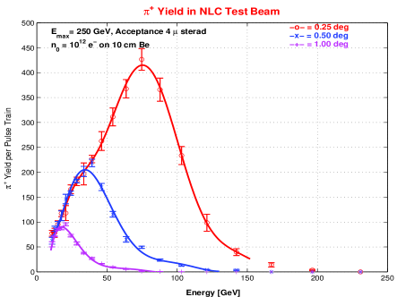
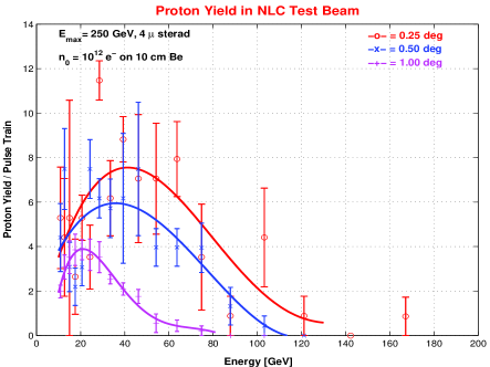
Figure 3 shows simulations fluka of pion and proton yields at production angles of 0.25∘, 0.5∘ and 1.0∘ for a 250 GeV electron beam of intensity 1012/pulse train on a 0.3 rl Be target in a secondary beam line of acceptance 4 sr and = 4%. The curves show that the yield at 1∘ is large enough for lower energies, but that the maximum energy of particles is a function of angle, so smaller angles give more latitude in choosing the right yield at higher secondary energies. Kaon yields are somewhere in between. Not enough test particles were used in these simulations to determine if enough yield is produced at an angle of 1∘; this will be investigated at a later time.
II.2 Fixed Target Experiments
Figure 4 shows the concept of a combined test beam and fixed target facility. The beams after the dump are bent and sent through a system of slits. These slits will be designed to define the momenta of the particles for the test beam application and to clean up the remainder of the tails of the disrupted beams for fixed target experiments.
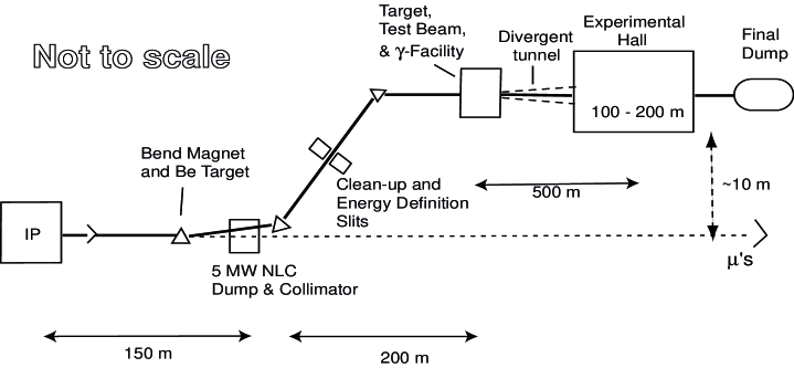
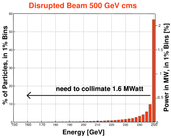
Figure 5 shows the energy distribution of the 250 GeV disrupted beam and the disrupted power in 1% bins, calculated using the beam-beam program GUINEAPIGguineapig . In order to achieve a of 1%, the quality required for fixed target experiments (see below), 1.6 MW have to be collimated in the transport line to the experimental area. As an existence proof, the energy defining slits (SL-10) in the SLAC A-line are designed for such power. In the NLC case, not all power has to be absorbed by the energy defining slits because some will be absorbed by the 5 MW dump.
At higher cms energy (1 TeV), the beams at collision are smaller, and the beamstrahlung and coherent pair production effects more severe. The use of disrupted beams at higher energy also seems possible, but needs more study.
III Requirements on the Fixed Target Beams and Possible Experiments
III.1 Requirements on the Beam Parameters
The demands on beams for fixed target physics are very modest compared to the demands of luminosity production with colliding beams. For colliding beams both beams must have a very small emittance, and both the electron and positron system must be working at the highest level.
These requirements do not apply for fixed target experiments. Here the luminosity is determined by the number of beam particles and the density of the target, and not the emittance of the beams. Luminosities of 1039 cm-2 sec-1 can be achieved; this is 4-5 orders of magnitude larger than in colliding beam experiments. Furthermore, only the system for producing polarized electrons is needed.
Traditionally, in preparing collider experiments a “Snowmass year” = 107 sec, corresponding to 32% efficiency, is used for run time calculations. Because of the relaxed conditions we will use *32% = 45% efficiency for fixed target experiments at the NLC. This number compares well with the experience at SLAC.
| Parameters | Value Required |
|---|---|
| Energy spread | 1% E |
| Polarization | 80% |
| Beam size | 1 mm |
| Charge jitter | 2% |
| Position jitter on target | 100 m |
| *Beam asymmetries | 10-9 Q |
| *Position asymmetries | 10 nm |
Requirements of fixed target electron beams: These requirements are similar to present day spin physics experimental needs, properties already achieved in End Station A at SLAC. The two last quantities (*) are the uncertainties with respect to the polarization state integrated over an entire run.
As shown above, the specific requirements of energy spread and polarization for fixed target experiments can be achieved, even with disrupted beams. This opens up parasitic use of otherwise unused beams, thus enhancing the physics value of operations at moderate cost.
III.2 Fixed Target Area Design Parameters
The fixed target area, including the targets, must be accessible during colliding beam operations to make installation and operation of the fixed target experiments efficient and independent from the colliding beam operation. The main colliding beam dump at 200 m is assumed to be hermetic, except for ’s. Muons range out with 0.4 m per GeV in earth and a transverse spread of about 10 m. At 250 GeV they will reach 600 m in the earth beyond the main colliding beam dump, so the transverse separation of the experimental area from the primary line-of-flight of the ’s has to be at least 10 m.
This optimal scattering angles at 250 GeV are 1-4 mrad for Møller experiments and 20 mrad for spin structure experiments. This in turn requires large drift sections to have enough transverse space available for the spectrometers. The target and spectrometer locations can be separated by a divergent tunnel to minimize the excavation costs of an experimental hall.
III.3 Possible Experiments
Below is a list of possible experiments which should continue to be interesting ten years from now, thereby opening a window of opportunity for NLC. The availability of high energy, high flux and high polarization -beams will spawn new and exciting proposals because the figure of merit of -absorption experiments increases with energy.
Experiments with (e,e′):
-
•
ALR by Møller scattering (sin2W)
-
•
Spin structure functions at very low
Experiments with -absorption :
-
•
Polarized gluon density G
-
•
Gerasimov-Drell-Hearn sum rule (GDH)
-
•
General charm physics
With a backscattered laser beam, quasi-monochromatic ’s of 200 GeV energy can also be produced, but at much lower intensities.
As listed above, with -absorption, the gluon spin contribution G in the nucleon can be determined. This is an interesting possibility via open charm production from g fusion, because the cross section for N - cc̄X at 200 GeV is 700 nb, so that the event rate with a primary -beam will be very high. An experiment using muons, but similar in kinematics with a much lower event rate, is COMPASS at CERN compass . A new proposal to do such measurements at SLAC with a 45 GeV coherent bremsstrahlung beam (SLAC-Proposal E-161, slace161 ) has just been approved.
Another experiment which could have a very large impact on the physics of charm mixing, is N - cc̄X. Here the cross section is 3 orders of magnitude larger than at B-factories. The kinematic boost is large compared even to asymmetric B-factories, opening up a new regime for lifetime determinations, D0-mixing and CP-violation. This experiment would improve on the work of the FOCUS collaboration (FermiLab E831, focus ) which used a 250 GeV endpoint broad band bremsstrahlung beam from secondary electrons and positrons produced from the 800 GeV Tevatron proton beam.
III.4 Specific Example: The Running of sin2W by Polarized Møller Scattering
SLAC is currently finishing construction of a 50 GeV fixed target experiment to measure the weak mixing angle Kumar95 at low momentum transfer (off the Z) with Møller scattering with great precision (E-158, slace158 ). The first runs are scheduled for early 2001.
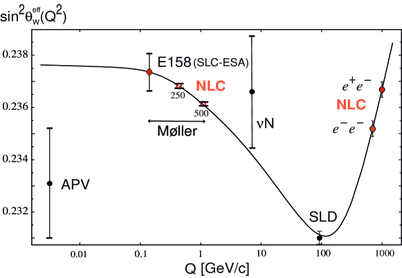
Figure 7 shows a theoretical prediction and several experimental measurements of sin2W as well as the predicted errors for two potential NLC fixed target experiments. Like other Weinberg angle measurements SLD , they are based on measuring ALR, the left-right asymmetry.
The table below shows the effect of beam energy on the Møller measurement error.
| Experiment | E-158 | NLC-I | NLC-II |
|---|---|---|---|
| E/GeV | 46.4 | 250 | 500 |
| ALR/10-7 | 3.2 | 16.1 | 32.2 |
| relative from ALR alone | 1 | 1/5.4 | 1/10.8 |
TABLE: Impact of beam energy on the Møller measurement error: as explained in the text the statistical error decreases with increasing beam energy. 100% polarization was assumed for the table.
The small errors result mainly from the fact that the left-right asymmetry is proportional to the beam energy: AE. This has a unique and beneficial consequence for Møller scattering. Generally in electron scattering the cross section is proportional to the inverse of the beam energy squared, , but in the case of Møller scattering the cross section is (see Ref. slace158 ). The figure of merit for this experiment, however, is . The consequence is that the statistical error decreases with increasing beam energy. The point in Figure 7 at NLC-250 assumes a total charge of 170 Coul on target. Assuming the nominal NLC beam of 1012 electrons per bunch train, this corresponds to eight months running at 45% efficiency using an undisrupted beam. For the disrupted beam, 57% of the beam is within E/E = 1%. In this case 120 Coul can be collected in nine months running, or 170 Coul in 13 months.
In summary for Møller scattering, the use of disrupted beams is possible and the beam depolarization due to colliding beams is small. Within about one year of running at NLC energies, the compositeness of the electron can be probed at the 60 TeV scale and the existence of an extra Z-boson, Z′, can be verified or excluded up to 2.7 GeV. An important cross check on the Higgs mass can be performed at the 10% level kumar96 .
IV Summary
Single beam use at the NLC offers possibilities for a wide variety of fixed target experiments at (relatively) modest cost. We have investigated the possibilities of attaching a single beam facility to the low energy IR at 250 GeV maximum energy for polarized electrons, 200 GeV for polarized quasi-monochromatic photons. Other locations are possible. NLC detector development and testing, in particular for a detector in the HE IR, is possible with the early availability of a 250 GeV test beam.
Acknowledgments
We would like to thank: Peter Bosted (University of Massachusetts, Amherst),
David Burke (SLAC), Don Crabb (University of Virginia),
Krishna Kumar (University of Massachusetts, Amherst), Mike Olson (St. Norbert College),
Tom Markiewicz (SLAC),
Makis Petratos (Kent State University) and Terry Toole (American University),
for much and diverse help and contributions.
References
- (1) E-142 Collaboration, P.L. Anthony, “Deep Inelastic Scattering of Polarized Electrons by Polarized 3He and the Study of the Neutron Spin Structure”, Phys.Rev. D54:6620-6650,1996; “Determination of the Neutron Spin Structure Function”, Phys.Rev.Letters 71:959-962,1993.
- (2) E-143 Collaboration, K. Abe et al., “Measurements of R=/ for 0.03x0.1 and Fit to World Data”, Physics Letters B452:194-200,1999; “Measurements of the Proton and Deuteron Spin Structure Functions g1 and g2”, Phys.Rev.D58:112003-112061, 1998; “Measurement of the Proton and Deuteron Spin Structure Function g1 in the Resonance Region”, Phys.Rev.Letters 78:815-819,1997; “Measurement of the Q2-Dependence of the Proton and Deuteron Spin Structure Functions gp1 and gd1”, Physics Letters B364:61-68,1995; “Measurements of the Proton and Deuteron Spin Structure Function g2 and Asymmetry A2”, Phys. Rev. Letters 76:587-591,1996; “Precision Measurement of the Deuteron Spin Structure Function gd1”, Phys.Rev.Letters 75:25-28,1995.
- (3) E-154 Collaboration, K. Abe et al., “Measurement of the Neutron Spin Structure Function gn2 and Asymmetry An1”, Physics Letters B404:377-382,1997; “Next to Leading Order QCD Analysis of Polarized Deep Inelastic Scattering Data”, Physics Letters B405:180-190, 1997; “Precision Determination of the Neutron Spin Structure Function gn1”, Phys.Rev.Letters 79:26-30,1997.
- (4) E-155 Collaboration, P.L. Anthony et al., “Measurement of the Deuteron Spin Structure Function gd1(x) for 1 (GeV/c)2Q240 (GeV/c)2 ”, Physics Letters B463:339-345, 1999; “Inclusive Hadron Photoproduction from Longitudinally Polarized Protons and Deuterons”, Physics Letters B458:536-544,1999; “Measurement of the Proton and Deuteron Spin Structure Functions g2 and Asymmetry A2”, Physics Letters B458:529-535, 1999.
- (5) E-144 Collaboration, C. Bamber et al., “Studies of Nonlinear QED in Collisions of 46.6 GeV Electrons with Intense Laser Pulses”, Phys.Rev. D60:092004:1-43,1999
- (6) E-146 Collaboration: M. Cavalli-Sforza et al., “A Method of Obtaining Parasitic or Beams during SLAC Linear Collider Operations”, SLAC-PUB-6387, 1993.
- (7) E-146 Collaboration: P.L. Anthony et al., “Bremsstrahlung Suppression due to the LPM and Dielectric Effects in a Variety of Materials”, SLAC-PUB-7413, LBL-40054, LBNL-40054, Feb 1997. 52pp. Published in Phys.Rev.D56:1373-1390,1997.
- (8) P. Anthony, “GLAST Beam Test at SLAC”, SLAC-PUB-7323, Oct 1996. 21pp. Presented at Workshop on the Next Generation of High-Energy Gamma Ray Telescopes: Exploring the Astrophysics of Extremes, Greenbelt, MD, 4-6 Sep., 1996.
- (9) C. Adolphsen et al., “Zeroth Order Design Report for the Next Linear Collider”, SLAC-Report 474 (1996).
- (10) A. Fasso, A. Ferrari, P.R. Sala and J. Ranft, “FLUKA: Status and Prospective for Hadronic Applications”, A. Fasso, A. Ferrari, P.R. Sala, “Electron-Photon Transport in FLUKA: Status”, Proc. of Conf. MC2000 (Advanced Monte Carlo for Radiation Physics, Particle Transport Simulation and Applications) Lisbon, 2000.
- (11) D.Schulte, Ph.D. Thesis (University of Hamburg, 1996); TESLA-97-08.
- (12) K.Yokoya, “User’s Manual of CAIN”, 1997.
- (13) http://www.slac.stanford.edu/exp/e161/
- (14) http://wwwcompass.cern.ch/
- (15) S. Bianco, “New FOCUS Results on Charm Mixing and CP Violation,” hep-ex/0011055, and http://www-focus.fnal.gov.
- (16) K.S. Kumar, E.W. Hughes, R. Holmes and P.A. Souder, “Precision Low-energy Weak Neutral Current Experiments”, Mod. Phys. Lett.A10:2979,1995.
- (17) R. Carr et al., “A Precision measurement of the Weak Mixing Angle in Møller Scattering”, SLAC-Proposal-E-158, 1997.
- (18) A. Czarnecki and W. Marciano, “Polarized Møller Scattering Asymmetries”, BNL-HET-00/2, hep-ph/0003049, Int.J.Mod.Phys.A15:2365-2376,2000.
- (19) W. Marciano, “Precision Electroweak Parameters and the Higgs Mass”, BNL-HET-00/04, hep-ph/0003181.
- (20) T. Abe, “The Final SLD Results for ALR and Alepton”, SLAC-PUB-8646, 2000, Invited talk presented at the 30th International Conference on High Energy Physics, Osaka, Japan, July 27 - August 2, 2000.
- (21) Krishna Kumar, “Fixed Target Møller Scattering at the NLC”, in Snowmass 96, new Directions for High Energy Physics, American Physical Society, 1996.