STUDIES OF BEAM OPTICS AND SCATTERING IN THE NEXT LINEAR COLLIDER POST-LINAC COLLIMATION SYSTEM ††thanks: Work supported by U.S. Department of Energy, Contract DE-AC03-76SF00515
Abstract
We present a new conceptual and optical design for the Next Linear Collider post-linac collimation system. Energy collimation and passive protection against off-energy beams are achieved in a system with large horizontal dispersion and vertical betatron functions. Betatron collimation is performed in a relatively low-beta (FODO-like) lattice in which only thin spoilers intercept particles near the beam core, while thick absorbers maintain a large stay-clear from the beam. Two possible schemes for the spoilers are considered: one in which the spoilers are capable of tolerating a certain number of damaging interceptions per collider run (”consumable” spoilers), and one in which the spoilers are potentially damaged on every machine pulse and are self-repairing (”renewable” spoilers). The collimation efficiency of the system is evaluated, considering both halo particles which are rescattered into the beam and muon secondaries which are passed to the interaction region. We conclude that the new design is a promising candidate for the NLC post-linac system.
1 Introduction
The experience of the Stanford Linear Collider (SLC) indicates that collimation of the beam halo at the end of the main linacs of the Next Linear Collider (NLC) will be a necessity. The principal requirements on the NLC post-linac collimation system are as follows:
-
•
The system should stop particles which would generate unacceptable backgrounds in the detector from entering the final focus
-
•
The collimation efficiency should be sufficiently high that the number of halo particles which are transmitted to the final focus is comparable to the number generated by beam-gas and thermal-photon scattering from the collimation region and the final focus
-
•
The number of muon secondaries from the collimation system which reach the detector must be minimized
-
•
The optical and wakefield dilutions of the beam emittances due to the collimation system must be small
-
•
The system must protect the final focus and the detector from beams which have large energy or betatron excursions without being destroyed in the process.

The 1996 NLC design included a post-linac collimation system shown in Figure 1 [1]. The system design was driven primarily by the machine protection requirement that a single bunch train (80 kJ at 500 GeV per beam) at nominal emittances ( mm.mrad) should not be able to damage the collimators. This required a scheme of optically-thin spoilers and thick absorbers in each plane, large betatron functions, and strong optics, which in turn introduced difficulties due to nonlinearities and wakefields.
The difficulties envisioned in the operation of the collimation system led to reconsideration of the design assumptions and a new conceptual design.
2 Design Assumptions
The design of the post-linac collimation system is most strongly governed by the expected properties of large excursions which can impact the collimators. Previously it had been assumed that neither energy nor betatron excursions could be trapped actively in the NLC due to its low repetition rate (120 linac pulses per second). A re-examination of the SLC operational history, as well as that of other accelerators, indicated that failures which could cause a fast (inter-pulse) betatron oscillation of the required magnitude were either rare or could be eliminated by design, while pulse-to-pulse energy variations of the required magnitude cannot be ruled out for a linac.
The expected charge of the beam halo was originally particles per linac pulse (1% of the beam), based on early SLC experience. Later SLC experience showed that the halo could be reduced substantially through careful tuning of the injection (damping ring and compressor) systems. In the present NLC design a collimation system downstream of the damping ring and first bunch compressor is expected to dramatically reduce the halo intensity at the end of the main linac. The present estimate of the halo is particles per pulse; we have chosen to design for a safety factor of 100 over this estimate. This reduction eliminates the requirements for water cooling in the spoiler elements and eases the tolerances on muon generation.
3 New Collimation System Optics
Figure 2 shows the optical functions of the new post-linac collimation lattice. The energy and betatron collimators are separated, with the former preceding the latter.

3.1 Energy Collimation
The energy collimation section achieves passive protection against off-energy pulses through a 0.5 radiation length (R.L.) spoiler and a 20 R.L. absorber separated by approximately 30 meters. The first few R.L. of the absorber are titanium, for which the RMS beam size must be larger than 560 m to ensure survival [2]. Beams which pass through the spoiler will develop RMS scattering angles of 19 radians in horizontal and vertical; combined with the dispersive beam size at the absorber (), the expected size of a beam at the absorber which first passes through the spoiler is 660 m.
Survival of the 0.5 R.L. spoiler is also a consideration. At the spoiler location in the energy collimation region, m. For the NLC bunch train at 500 GeV per beam, the minimum beam size for survival of a 0.5 R.L. beryllium spoiler is approximately 50 m, thus we have chosen beryllium as the material for the spoilers [3].
The collimation depth in energy should be narrower than the bandpass over which beams are well-behaved in the final focus. The present system is designed to remove off-energy particles, which requires a half-gap of 1.3 mm for the spoilers and 2.0 mm for the absorbers.
The jitter amplification effect of collimator wakefields must be minimized at all points in the collimation system. In the energy collimation region, the ratio is large and thus the collimator wakefields primarily couple energy jitter into horizontal position jitter. This aberration is cancelled by placing a second spoiler-absorber pair at a location which is in betatron optics from the first pair but with equal dispersion functions. The cancellation is only exact for on-energy particles, but the expected energy jitter of 0.22% only causes a horizontal jitter of 0.5% of . A similar effect is caused by high-order dispersion, but the effect is approximately 1/3 as large as the residual wakefield jitter contribution.
3.2 Betatron Collimation
Because large betatron oscillations are not expected to develop during one inter-pulse period, it is expected that the betatron collimators will rarely be hit by the beam core. The baseline design for the betatron collimation system, which is the system pictured in Figure 2, utilizes “consumable” spoilers, in which the spoilers can be moved to present a fresh surface to the beam after every incident of beam-core interception; we assume that 1,000 such incidents can occur per year of operation. An alternative design would permit damage on every pulse and require that the collimators be self-repairing, “renewable” collimators. While more techincally challenging, the renewable collimators would permit smaller apertures to be used, which in turn would permit smaller betatron functions.
The system in Figure 2 is based on a triplet lattice with phase advances of and per cell in horizontal and vertical, respectively. Thus the system collimates in two phases, two planes, two iterations per phase/plane. Each high-beta region in the system contains 2 adjustable spoilers ( and ) and 2 fixed cylindrical absorbers. Multiple coulomb scattering in the spoilers gives the halo a large angular divergence, which causes particles to hit the absorbers in the next cell.
The required collimation aperture is set by acceptable limits on synchrotron radiation in the final doublet. Based on studies of the 1996 final focus [4], the nominal spoiler half-gaps are approximately 200 m for 500 GeV beams. The fixed absorbers have a round aperture with a radius of 1 mm. Spoilers and absorbers are 0.5 and 20.0 R.L., respectively.
The vertical jitter amplification factor for the betatron collimation system is 46%, smaller than the 66% expected for the 1996 design. For the expected incoming jiter (0.375 ), the collimators contribute 0.17 jitter in quadrature with the incoming jitter. These estimates are based on analytic models for collimators with a taper and a large aspect ratio [5]; however, recent experiments indicate that the actual wakefield effect may be smaller than this [6]. The horizontal jitter amplification is expected to be about half that of the vertical.
4 Scattering Studies
The efficiency of primary-particle collimation and the production of muons which are transmitted to the IP were studied using a combination of TURTLE, EGS, and MUCUS (MUltiple CoUlomb Scattering program).
4.1 Primary Particles
Figure 3 shows the halo attenuation based on tracking of 2 million halo particles which originate at a point on one collimator. Figure 3 (a) shows the attenuation for particles 240 m from the beam axis at each of the first 4 spoilers (2 vertical, 2 horizontal); the attenuation is shown for cases in which off-energy primary particles are collimated downstream of the collimation system (eliminating particles which are more than 2% off-energy), and cases without downstream energy attenuation. The attenuation is typically between and , while the desired value is . Figure 3 (b) shows the attenuation as a function of source offset for the first spoiler.
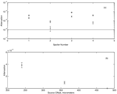
Note that these estimates are preliminary, and recent studies have indicated that a substantial improvement may be achieved by optimizing the positions of the spoilers. Also, increasing the spoiler thickness to 1.0 R.L. would improve attenuation by an order of magnitude, but the resulting energy deposition in the spoilers would have to be studied.
4.2 Muon Secondaries
The problem of muon secondaries from the post-linac collimators entering the detector is more severe than it was for the 1996 NLC design, primarily because the collimation system and final focus are shorter in the present design (2.5 km per side compared to 5.2 km per side), which puts all sources of muons closer to the IP. In the present design, we include two large magnetized toroids for muon attenuation on each side of the IP; despite this, we expect on the order of several hundred muons per linac pulse to enter the muon endcap of a detector similar to the “LCD Large” design [7], as well as tens of muons per linac pulse in the electromagnetic calorimeter. These studies were performed for 500 GeV beams; for 250 GeV beams, 2 orders of magnitude improvement are expected. The muon rate can also be reduced by adding additional spoilers, reducing the halo intensity, or constructing a smaller detector (such as “LCD Small”). Since the 500 GeV center-of-mass (CM) results are quite acceptable, a reasonable approach to the muon situation might be to build the system with 2 muon toroids and spaces allocated for additional toroids, to be added in later years if required.
5 Conclusions and Future Directions
We have presented an optics design for the Next Linear Collider post-linac collimation system which addresses the difficulties in the previous system design. The new system has weaker optics, looser tolerances, larger bandwidth, and better wakefield properties than the original. The new system is somewhat poorer than desired in the areas of halo attenuation and muon production; future work will seek to address this weakness..
The present energy collimator includes a 5 milliradian arc, which changes the angle between the linac and the final focus. Recent developments in final focus design have expanded the potential energy reach of the NLC [8]; in order to take full advantage of this change, we plan to redesign the collimation system to either a dogleg or a chicane, such that the post-linac system and the linac are co-linear and the former can be expanded by “pushing back” into the latter when the linac gradient and energy are increased.
6 Acknowledgements
This work would not have been possible without the ideas and assistance of G. Bowden, J. Frisch, J. Irwin, T. Markiewicz, N. Phinney and F. Zimmermann.
References
- [1] NLC Design Group, Zeroth-Order Design Report for the Next Linear Collider, 555-641 (1996).
- [2] NLC Design Group, Zeroth-Order Design Report for the Next Linear Collider, 573-574 (1996).
- [3] W. Ralph Nelson, private communication.
- [4] S. Hertzbach, private communication.
- [5] G. Stupakov, SLAC-PUB-7167 (1996).
- [6] P. Tenenbaum et al, these proceedings.
- [7] http://hepwww.physics.yale.edu/lc/graphics.html.
- [8] P. Raimondi and A. Seryi, these proceedings.