Universal Tunnelling Time in photonic Barriers
Abstract
Tunnelling transit time for a frustrated total internal reflection (FTIR) in a double–prism experiment was measured using microwave radiation. We have found that the transit time is of the same order of magnitude as the corresponding transit time measured either in an undersized waveguide (evanescent modes) or in a photonic lattice. Moreover we have established that in all such experiments the tunnelling transit time is approximately equal to the reciprocal () of the corresponding frequency of radiation.
Previous photonic tunnelling transit time experiments have been carried out using electromagnetic radiation both at microwave and optical frequencies. Such experiments were stimulated by the formal analogy between the classical Helmholtz wave equation and the quantum–mechanical Schrödinger equation. The corresponding tunnelling transit time data for e.g. electrons are not yet available.
In our Letter we are considering the tunnelling transit time for opaque photonic barriers enders1 ; steinberg1 ; spielmann ; ranfagni1 . We suggest that in general the transit or delay time is approximately equal to the reciprocal frequency of the corresponding radiation and that it is independent of the type or shape of the actual barrier. The transit time or group delay time is defined as , were is the tunnelling distance and . This definition agrees with that introduced by Eisenbud and Wigner who put merzbacher . The tunnelling transit time or just tunnelling time for short, is measured as the time interval between the respective times of arrival of the signal’s envelope at the two ends of the tunnelling length . We are not suggesting here that this is equivalent to the measure of the signal velocity within the barrier.
In order to justify this hypothesis of a universal tunnelling time we have carefully analyzed our own experimental results and those of others. Three different types of photonic barrier have been used. Investigations carried out in such experiments as shown in Fig.1.
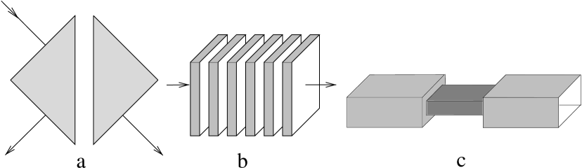
In Fig.1a the tunnelling effect occurs between two prisms (frustrated total internal reflection or FTIR) carey ; balcou ; mugnai , in Fig.1b tunnelling is modelled by the forbidden band of an one–dimensional photonic lattice steinberg1 ; spielmann ; nimtz1 , and in Fig.1c tunnelling occurs in the undersized section of the waveguide enders1 . Since in one dimension the Helmholtz and Schrödinger equations are similar, it is suggested that the three kinds of barrier can be used to model the one–dimensional process of wave mechanical tunnelling sommerfeld ; feynman .
Let us start by presenting some new data on the double–prism experiment. For and an angle of incidence the incoming beam penetrates into the second medium and travels for some distance along the interface before being scattered back into the first medium (see Fig.2); here and are respectively the refractive indices of the first prism and of the air. If a second prism with is used to probe the “evanescent” component of the wave, the total reflection becomes “frustrated” and photonic tunnelling across the air gap takes place.
It is indicated in Fig.2 that the barrier traversal time of the double-prism, or what we call here the tunnelling time can be split into two components , one along the surface due to the Goos-Hänchen shift , and another part perpendicular to the surface artmann . The measured tunnelling time represents the group or phase time delay as explained earlier.
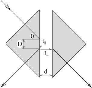
The first component is related to a non-evanescent wave characterized by the real wavenumber while the second one is related to the evanescent mode traversing the gap between the two prisms. (, is the corresponding vacuum wavelength, and the refractive index of both prisms.)
The Goos-Hänchen shift is a sensitive function of the gap width , the frequency of radiation and its polarization, the beam width and the angle of the incoming beam balcou ; cowan ; horowitz . With increasing air gap the shift reaches a constant asymptotic value = balcou ; cowan , where is the phase shift of the reflected or transmitted beam.
We have performed a double-prism experiment with two prisms of perspex, obtained from a 400 mm cube by a diagonal cut. The corresponding refractive index of gives a total reflection angle of = 38.68∘. Microwave radiation at GHz generated by a 2K25 klystron was fed to a parabolic dish antenna which transmitted a near parallel beam to the prisms. (Beam spread was less than 2∘).
In order to appoint the tunnelling time we measured the time for a signal travelling the closed and the opened prism. The transmission time through the opened prism is faster than through the closed prism. Considering the modifications of the path length the tunnelling time was determinated from the difference of both times.
The signal was then picked up by a microwave horn antenna and fed amplified to an oscilloscope (HP 54825A). Due to the Goos–Hänchen shift (see Fig.2) the position of the beam’s maximum had to be found by scanning the reflected and transmitted beams. It was found that the signal had a Gaussian-like shape, its half-width being 8 ns nimtz2 .
Since the total propagation time (antenna–prism–antenna) is longer than the signal half–width, it is safe to assume that the transmitter, the prism, and the detector are well decoupled since there is no danger of the circuit components being coupled by a standing wave building up. The experimental set–up permits asymptotic measurements.
The tunnelling time was measured at the frequency of 8.345 GHz (vacuum wavelength = 36 mm) using a TE-polarized beam. The beam diameter was 190 mm and the angle of incidence was chosen to be = 45∘.
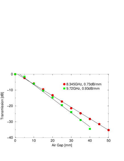
We tested whether all beam components were parallel and whether the angle of incidence was within the regime of total reflection by measuring at two different frequencies the transmission as a function of the gap between the two prisms. The measured transmission was 0.73 dB/mm at 8.345 GHz and 0.93 dB/mm for 9.72 GHz respectively compared to the theoretical values of 0.76 dB/mm and 0.94 dB/mm (see Fig.3). This agreement between the theoretical (as quoted for in feynman ) and experimental results indicates that our method of measuring FTIR is very sensitive, provided the boundary conditions are well defined.
The tunnelling time was measured in the regime of constant asymptotic Goos–Hänchen shift , where in our case (see experimental parameters given above) mm. The time for the Goos–Hänchen shift can be obtained from balcou by writing:
| (1) |
For = 31 mm, n = 1.605 and = 45∘ we obtain from (1) = 117 ps. Actually this value equals the measured Goos–Hänchen time for the total reflected beam in the absence of the second prism. (The measured time was obtained by properly taking into consideration the beam’s path in the prism.) As mentioned before for a transmitted beam the total tunnelling time is the sum of the two components and .
Surprisingly the measured total tunnelling time proved to be equal to alone. Since our accuracy of time measurement was 10 ps, this means that 10 ps or at least = 0.
Thus it would appear that the measured total tunnelling time depends mostly on the Goos-Hänchen shift and hence is approximately equal to the Goos–Hänchen time . This result is compatible with some theoretical investigations bearing in mind the imaginary wavenumber of the evanescent mode in the gap stahlhofen .
For large gaps where the transit time does not depend on the theoretical value for the FTIR-tunnelling time is 82 ps, using the model of Ghatak and Banerjee ghatak . This value is quite near to the measured value of 117 10 ps. It is now quite interesting to note that the reciprocal of the carrier frequency, ps, gives approximately the same value for the time interval as the measured tunnelling time. This result is also in agreement with the theoretical model of Ghatak and Banerjee, being valid over a wide range of frequencies and at all angles of incidence, except in the vicinity of the critical angle and for (grazing incidence) (see Fig.4).

This relationship we have obtained for FTIR seems to be a universal property of many tunnelling processes.
Some previously obtained experimental results are collected in Table 1; they all seems to confirm the suggested universal property that the tunnelling time is approximately equal to the reciprocal of the carrier frequency. Some deviations may have arisen from two experimental short comings: the studied barriers have not been sufficiently opaque or some tunnelling experiments were too difficult to perform.
| Photonic Barrier | Reference | Tunnelling Time | Reciprocal Frequency |
|---|---|---|---|
| Double–Prism FTIR | this paper | 117 ps | 120 ps |
| Carey et al. carey | 1 ps | 3 ps | |
| Balcou/Dutriaux balcou | 40 fs | 11.3 fs | |
| Mugnai et al. mugnai | 134 ps | 100 ps | |
| Photonic Lattice | Steinberg et al. steinberg1 | 1.47 fs | 2.3 fs |
| Spielmann et al. spielmann | 2.7 fs | 2.7 fs | |
| Nimtz et al. nimtz1 | 81 ps | 115 ps | |
| Undersized Waveguide | Enders/Nimtz enders1 | 130 ps | 115 ps |
Our experimental data obtained from FTIR using microwave radiation show that the finite tunnelling time is largely dependent on the interference effects at the entrance boundary of the barrier. In the case of FTIR it is the time equivalent to the Goos-Hänchen shift as was first pointed out by Stahlhofen stahlhofen .
We have also checked using a waveguide at a microwave frequency of 8.85 GHz, whether a similar behaviour applies in the case of a photonic lattice type shown in Fig.1b. The measured group delay time ps of the reflected beam was found to be the same as the time measured for traversing the barrier, ps, or what we have called the tunnelling time. Once again there is no indication that the evanescent mode spend any time inside the barrier, similary to FTIR nimtz2 .
Hartman hartman calculated the tunnelling time (phase time delay) of Gaussian wave packets for one-dimensional barriers based on the time dependent Schrödinger equation. It is interesting to note that his theoretical wave-mechanical results are also in agreement with the photonic experiments for different barrier lengths enders2 .
All experimental measurements of the tunnelling time are in agreement with the theoretical calculations and indicate a universal tunnelling time in the case of opaque barriers. Both the measured finite total tunnelling time and the time delay of the reflected beam are associated with the front of the barrier and closely correlate with the reciprocal of frequency of the corresponding radiation.
We gratefully acknowledge helpful discussions with P. Mittelstaedt, A. Stahlhofen, R.–M. Vetter, and the Referee who made us familiar with the calculations of Ghatak and Banerjee. G.N. likes to thank X. Chen and P. Lindsay for stimulating discussions during his short stay at Queen Mary and Southfield College London.
References
- (1) A. Enders and G. Nimtz, J. Phys.I, France 2, 1693 (1992)
- (2) A. Steinberg, P. Kwiat, and R. Chiao, Phys. Rev. Letters 71, 708 (1993)
- (3) Ch. Spielmann, R. Szipöcs, A. Stingle, and F. Kraus, Phys. Rev. Letters 73, 2308 (1994)
- (4) A. Ranfagni, P. Fabeni, G. Pazzi, and D. Mugnai, Phys. Rev. E 48, 1453 (1994)
- (5) Merzbacher, E., Quantum Mechanics, 2nd ed., John Wiley & Sons, New York (1970)
- (6) J. J. Carey, J. Zawadzka, D. Jaroszynski, and K. Wynne, Phys. Rev. Letters, 84, 1431 (2000)
- (7) Ph. Balcou and L. Dutriaux, Phys. Rev. Letters 78, 851 (1997)
- (8) D. Mugnai, A. Ranfagni, and L. Ronchi, Phys. Letters A 247, 281 (1998)
- (9) G. Nimtz, A. Enders, and H. Spieker, J. Phys. I., France 4, 565 (1994)
- (10) A. Sommerfeld, ’Vorlesungen über Theoretische Physik’, Band IV, Optik, Dieterichsche Verlagsbuchhandlung (1950)
- (11) Feynman, R. P.,Leighton, R. B. and Sands, M., ’The Feyman Lectures on Physics’, Addison–Wesley Publishing Company, II 33–12 (1964)
- (12) Artmann, K., Ann. Phys. 2 87-102 (1948)
- (13) Cowan, J. J. and Anicin, B., J. Opt. Soc. Am. 67 1307-1314 (1977)
- (14) Horowitz, B. R. and Tamir, T., J. Opt. Soc. Am. 61 586-594 (1971)
- (15) A. A. Stahlhofen, Phys. Rev. A 62, 12112 (2000)
- (16) A. Ghatak and S. Banerjee, Appl. Opt. 28, 1960 (1989)
- (17) G. Nimtz, Eur. Phys. J. B 7, 523 (1999)
- (18) Th. Hartman, J Appl. Phys. 33, 3427 (1962)
- (19) A. Enders and G. Nimtz, Phys. Rev. E 48, 632 (1993)