Energy stabilization of 1.5 GeV S-Band linac
Abstract
KEK-ATF is studying low emittance, multi-bunch electron beam for the future linear collider. The energy instability of the 1.5 GeV linac has been a problem making the beam injection to the damping ring unstable. Because the unstable beam generates also large amount of the radiation, the beam current is limited by the KEK radiation safety policy much lower than what we expect. Stabilizing the S-band linac is therefore important not only to improve the beam quality, but also to clear the radiation safety limit to start the multi-bunch operation.
We have made various modifications to solve the problem on the electron gun, modulator, klystron etc. For the modulator, we have developed a feed-forward controlled De-Q module. This module compensates the voltage jitter by controlling the deQ timing with a feed-forward circuit because the amount of the excessive charge up is strongly correlated to the charge up slope that can be measured prior to the deQ timing. The energy stability was examined and was improved by a factor of 3, from 0.6% to 0.2% of itself. Modification for the feed-forward circuit to get more stability was made. The test for the new circuit is in progress. For the long term instability, phase-lock system for klystron RF is being installed. In the test operation, it showed a good performance and compensate the phase drift less than .
1 Introduction
KEK-ATF is a test facility to study the low emittance multi-bunch beam and beam instrumentation technique for the future linear collider. That consists from 1.5 GeV S-band linac, a beam transport line, a damping ring, and a diagnostic extraction line.
In the linac, the electron beam is generated by a thermionic electron gun. Typical intensity is electron/bunch. The bunch length shrinks from 1 ns to 10 ps by passing a couple of sub-harmonic bunchers, a TW buncher. The electron beam is accelerated up to 1.3 GeV by 8 of the S-band regular accelerating section. One section has two accelerating structures driven by a klystron-modulator. Klystron is Toshiba E3712 generating 80 MW with a pulse duration of RF. A peak power of 400 MW with a pulse duration of is obtained by SLED cavity and makes a high gradient accelerating field, 30 MeV/m.
20 of bunches separated by 2.8 ns are accelerated by one RF pulse. This multi-bunch method is one of the key technique in the linear collider, but ATF is now operated in single-bunch mode because of the KEK radiation safety policy.
In April 2000, we achieved horizontal emittance , vertical emittance (both for , single bunch mode )[1] which are almost our target.
So, our next task is to achieve such low emittance with the high intensity, high reputation multi-bunch electron beam. To start the multi-bunch operation, we have to clear the radiation safety limit anyhow.
One of the biggest source of the radiation is the beam transport line. The large energy tail and the energy jitter causes the radiation loss in the beam transport line. To suppress the radiation , we have to stabilize the beam energy and also improve the quality of the beam.
In addition, the energy jitter fluctuates the injection efficiency to the damping ring, the beam intensity becomes therefore very unstable. The energy stabilization of the linac is very important for the systematic study for the beam instrumentation at the extraction line.
2 Feed-forward deQ
From a study of the energy instability[2], one of the biggest source of the instability was klystron voltage jitter induced by the fluctuated modulator output. We implement a new deQ method to compensate it.
In our modulator, the pulse forming network, PFN is charged up resonatorly up to 43 kV. By discharging , a pulse transformer gains this voltage up to 340 kV with pulse duration of 7.5 and is fed to the klystron.
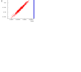
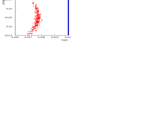
deQ module controls the voltage of PFN, . When reaches the reference voltage, deQ modules fires trigger to stop the charge up. Fig. 1 shows the correlation between and gradient of the charge up curve, . Ideally is independent from , but there is a significant correlation. This correlation is explained as follows; there is some delay to stop charging up and the delay causes excessive charge up which is expressed as where is the delay. This excess is therefore proportional to dV/dt and induces the correlation.
If dV/dt was always same, it was not a problem. In fact, the amplitude of AC power is unstable and that makes fluctuated dV/dt. Improving the quality of power source is straightforward, but it will be rather expensive. Then we admit the fluctuation of dV/dt and consider to compensate the jitter.
Because dV/dt is fluctuated and could not be zero, then the only way to compensate the fluctuation is to control to keep a constant excessive charge up. Fortunately, we can measure dV/dt prior to fire deQ signal, then feed-forward control is possible.
| mod. | #0 | #1 | #2 | #3 | #4 | #5 | #6 | #7 | #8 |
|---|---|---|---|---|---|---|---|---|---|
| off | .031 | .089 | .107 | .106 | .015 | .064 | .071 | .097 | .033 |
| on | .011 | .036 | .070 | .070 | .014 | .029 | .045 | .036 | .009 |
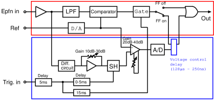
Fig. 2 shows block diagram of feed-forward deQ controller. Upper part shows that for the conventional deQ circuit. Lower part shows the feed-forward circuit. dV/dt is obtained by a differential circuit. Difference signal of dV/dt and the reference is used to determine the delay of deQ signal by using a voltage control delay. Gain of the amplifiers are optimized to make independent from dV/dt.
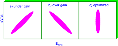
Fig. 3 schematically shows -dV/dt correlation in three cases: a) under gain, b) over gain, and c) optimized. By looking such plot, we optimized the gain of feed-forward circuit for 9 modulators.
Table 1 shows the stability of with and without feed-forward control. The unit is . Except for modulator #4, there was significant improvement for the stability up to factor of 3.
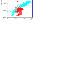
Fig. 4 shows the correlation between momentum jitter, and amplitude of AC 200V line. Momentum jitter was measured in beam transport line where the dispersion function was large. The dispersion function was calculated by a software for beam dynamics, so called SAD implemented by KEK scientists. Blue and red(or light and dark) areas show data taken without and with feed-forward control respectively. In this plot, we can see a clear dependence of momentum to the amplitude, but it is compensated by feed-forward deQ. The momentum jitter was decreased from 0.6% to 0.2% peak-to-peak.
Fig. 5 shows curve with feed-forward control. This strange shape can be explained as follows; although the feed-forward control should be driven by dV/dt measured at the end of the charge up curve (), dV/dt is actually measured at the middle of the charge up curve(). The gain for dV/dt, is therefore adjusted like and is used instead of .
Due to the sine shape of the charge up curve, the gain is a function of deQ timing. Because deQ timing changes according to dV/dt, then is a function of dV/dt. On the other hand, is a constant in our circuit. As a result, where dV/dt is large(small), is too large (small) and feed-forward control becomes over(under) gain.
To fix the problem, the gain have to be changed according to input signal (dV/dt). By introducing a linearizer to the feed-forward circuit, the gain can be changed continuously as a function of input signal. A modified feed-forward circuit was implemented with three linearizers. The test is now in progress.
3 Phase-lock system
Because the experimental hall where ATF is placed does not have a good thermal condition, the klystron gallery temperature is drifted in one day. RF phase is also drifted of S-band frequency.
To stop the RF phase drift, we have introduced a phase lock system. The block diagram of the system is shown in Fig. 6.
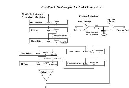
RF reference distributed through an optical line is separated into two lines after the phase shifter. One is for the reference of the phase detector which observes phase drift at the klystron output. Another is for klystron input through another phase shifter controlled by the phase-lock system to absorb klystron phase drift. Feed-back module gains the phase detector output and cuts the high frequency component to prevent oscillation of the feed-back loop.
The phase-detector is developed by Nihon-koshuha originally for KEKB RF system. For our purpose, it was modified for pulsed RF by adding sample hold circuit. In this module, phase is measured by taking ExOR of two inputs gained by limiter amplifiers. Due to this logic, output phase is independent from input RF amplitude. Table 2 shows the specifications.
| item | spec. |
|---|---|
| frequency | |
| input pulse duration | 300 ns C.W. |
| reference dynamic range | |
| test dynamic range | |
| phase detectable scope | |
| phase resolution |
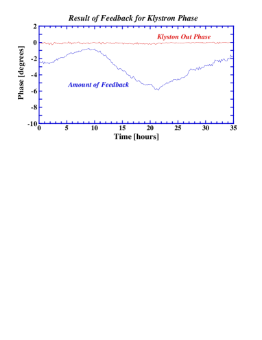
Fig. 7 shows a result of a test for the phase-lock system. Klystron RF phase was stabilized within peak-to-peak by the phase-lock system with the amount of the feed-back up to . Accounting for systematic error, the klystron RF phase was stabilized within .
The phase-lock system will be introduced for all klystrons soon. This system will suppress the long range energy drift of the S-band linac.
4 summary
To suppress the energy instability of the S-band linac, feed-forward control deQ was introduced. The momentum jitter was measured at the beam transport line and was improved from 0.6% to 0.2% by the feed-forward deQ. For further improvement, the feed-forward circuit was modified to correct the curve shape of dV/dt- relation by using linearizers.
For the long term phase drift of klystron RF, a phase-lock system was examined and stabilized the RF phase within . The phase-lock system will be introduced for all klystrons soon.
References
- [1] http://lcdev.kek.jp/ATF/
- [2] H. Hayano et al. , ’Klystron RF stabilization using feed-forward circuit’, 19th International linac conference at Chicago, 1998