Results of an RF Pulsed Heating Experiment at SLAC††thanks: Work supported by Department of Energy Contract DE-AC03-76SF00515
Abstract
Results are reported from an experiment on RF pulsed heating of copper at SLAC. Damage in the form of cracks may be induced on the surface after the application of many pulses of RF. The experiment consists of two circularly cylindrical cavities operated in the TE011 mode at a resonant frequency of 11.424 GHz. Each cavity received 8.5 MW, 1.2 s pulses at 60 Hz corresponding to a calculated temperature rise of 120 K on the copper surface. After 5.5107 pulses, the experiment was stopped and the copper surfaces were examined. Damage is present on the area of the surface where the maxiumum heating occurred.
1 INTRODUCTION
RF pulsed heating is a process by which a metal is heated from magnetic fields on its surface due to high-power pulsed RF. Since the heating occurs over a short time, the inertia of the material prevents expansion and thermal stresses are induced. If these stresses are larger than the elastic limit, known as the yield strength, then damage in the form of microcracks on the surface may occur after many pulses. This type of damage is known as cyclic fatigue. For fully-annealed OFE copper, we expect this damage to occur above temperature rises of 40 K [1]. However, this expectation is based on a static yield strength. It may be more appropriate to use a dynamic yield strength to predict the damage threshold, which may be two to three times higher [2, 3].
This experiment to study RF pulsed heating on copper consists of circularly cylindrical cavities operating in the TE011 mode at a resonant frequency of 11.424 GHz. The dimensions of the cavities were chosen to maximize the heating on the endcaps which are the test pieces of the experiment and were designed to be removable. For more details see [4, 5, 6].
2 PARAMETERS OF EXPERIMENT
2.1 Endcap preparation
Two cavities were connected to a 50 MW X-band klystron through a magic-tee in order to protect the klystron from reflected power. Four endcaps are tested at one time with this setup. The endcaps are approximately 22 mm in radius and made of OFE copper. They are cut to a class-16 finish and then brazed onto stainless-steel rings so they could be welded onto stainless-steel pistons that are inserted into the cavities. Before welding, the endcaps are diamond fly-cut to a mirror-finish and cleaned for vacuum with a light chemical etch. The damage from pulsed heating depends on the material and on surface preparation, and the chemical etch may have had significant influence on the results of the experiment [7].
2.2 Cavity parameters
The unloaded and external cavity Q’s were measured with a network analyzer before and after the experiment. These values are listed in Table 1.
| Cavity # | Theoretical | Initial | Final | Initial | Final |
|---|---|---|---|---|---|
| Q0 | Measured Q0 | Measured Q0 | Measured Qext | Measured Qext | |
| 1 | 21890 | 20350 | 14360 | 12315 | 7690 |
| 2 | 21890 | 20610 | 16810 | 12220 | 7140 |
3 RESULTS
Each cavity received 1.2 s, 8.5 MW square pulses from the klystron. The surface magnetic field at the endcaps is radial with a variation along the radius. The maximum field and temperature rise occur at a radius of 10.6 mm. The calculated maximum temperature rise on the surface is 120 K based on measurement of the input power. For details about this calculation see [4, 5]. The experiment was run for 5.5107 pulses at this temperature rise. After completion, final measurements of the cavity Q’s were taken and are listed in Table 1. The endcaps were then removed and examined.
RF breakdown occured at the coupling irises and initially limited the input power to 8.5 MW. Although the cavity eventually processed, we elected to remain at a temperature rise of 120 K to simplify the accounting of the pulses. After the end of the experiment, we discovered the coupling irises were melted on the inside of the cavity. Since the holes became effectively larger, the coupling to the TE011mode was increased. This explains the reduction in the external Q’s.
In Figure 1, one can see a visible change in the crystal grains in the region approximately 10.4 mm to 11.0 mm from the center with an average width of approximately 4 mm to 5 mm.
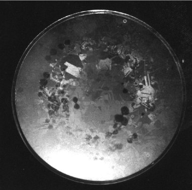
From GdifdL [8] simulations, the fields in the region closer to the coupling iris is 5% higher than the fields diametrically opposite of this region. This simulation would then explain why there is more damage in the region closer to the aperture, since the region farther away has a temperature rise approximately 10% lower.
Several other effects that are not critical to the central goal of measuring damage from pulsed heating were also observed. Initial examinations have shown that copper sputtered onto the endcaps from the coupling irises. The density of the copper globules increases closer to the plane of the coupling irises. One may also see dark circles along the area of maximum magnetic field. Since they seem to occur in pairs and the magnetic field in this area is radial, we believe these patches are due to multipacting. However, it is not yet understood why this occurs since the electric field in this region is zero.
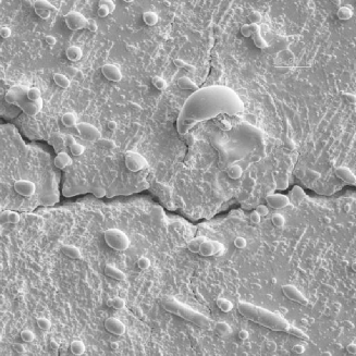
The endcaps were examined with a scanning electron microscope using secondary emission and a 5 keV electron beam. Figure 2 shows a region where maximum damage is expected.
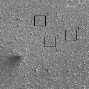
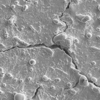
Note that this endcap pictured is different from the one shown in Figure 1; however, all four endcaps are similar in appearance. The little bumps along the surface are the copper globules sputtered from breakdown at the coupling iris. More importantly, one can easily see the numerous cracks that have occured on the surface. For comparison, a region at the center where the temperature rise is close to zero is shown in Figure 3.
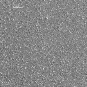
This picture was taken at the same magnification. There are no cracks in this region. The copper globules are also noticeable here. Because of the sputtering, we cannot isolate the unloaded Q degradation shown in Table 1 due to sputtering from that due to the presence of the cracks.
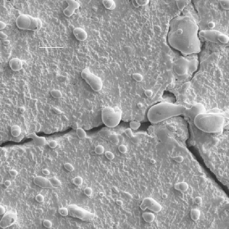
Each endcap was scanned along a random diameter. The scans show that cracks are only evident in the region of visible grains in Figure 1 where maximum damage is expected. Higher magnification images of the regions of cracks were taken. For the endcap shown in Figure 2, the average location of all higher-magnification images of cracks is approximately 10.4 mm from the center with a standard deviation of 1.3 mm. Close-up shots of a few of these cracks are shown in Figure 4.
An internal cross-section of the endcap shown in Figure 1 was completed. Not as many cracks were evident in the cross-section, but they did occur in the region of maximum temperature rise. One interesting crack is shown in Figure 5.
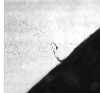
It begins at the surface and propagates down to an internal grain boundary. Afterwards, the crack propagates along the grain boundary.
4 CONCLUSION
We have demonstrated that RF pulsed heating with a temperature rise of 120 K poses a danger to OFE copper structures. The evidence is the surface modification and damage shown in Figures 1, 2, 4 and 5. We have measured degradation of the cavity Q0 also. Because of copper sputtered from breakdown at the coupling iris, it is not conclusive that this degradation was caused by the surface damage.
We are preparing one more experiment with OFE copper. The principle improvement will be use of the diagnostic TE012 mode to measure temperature rise and change of cavity Q during the RF pulse. This will also allow measurement of the evolution of Q0 during the course of the experiment.
RF pulsed heating is a limit to accelerator performance, and additional experiments need to be done for different temperature rises, pulse counts, materials and surface preparation.
5 ACKNOWLEDGEMENTS
The authors would like to thank Gordon Bowden for his help with the design of the test cavities. The authors would also like to thank Al Menegat for his assistance with running the experiment.
References
- [1] H.M. Musal, Jr., “Thermomechanical Stress Degradation of Metal Mirror Surfaces Under Pulsed Laser Irradiation”, Laser Induced Damage in Optical Materials 1979, pp. 159–173.
- [2] V.F. Kovalenko, Physics of Heat Transfer and Electrovacuum Devices, ch.7, Moscow: Sovetskoe Radio, 1975. In Russian.
- [3] O.A. Nezhevenko, “On the Limitations of Accelerating Gradient in Linear Colliders Due to the Pulse Heating”, PAC’97, Vancouver, Canada, May 1997.
- [4] D.P. Pritzkau, et al., “Experimental Study of Pulsed Heating of Electromagnetic Cabities”, PAC’97, Vancouver, Canada, May 1997.
- [5] D.P. Pritzkau, et al., “Possible High Power Limitations From RF Pulsed Heating”, 4th RF Workshop (RF98), Watsonville, California, October 1998. SLAC-PUB-8013.
- [6] D.P. Pritzkau, et al., “Experimental Design to Study RF Pulsed Heating”, PAC’99, New York, March 1999.
- [7] Prof. Reinhold Dauskardt, private communication, 2000.
- [8] Warner Bruns, GdfidL v1.2, 2000.