IIT-HEP-00/1
Energy Absorber R&D
Abstract
We describe the program of research and development being undertaken by a consortium of Illinois university groups to develop liquid-hydrogen energy absorbers for muon-beam cooling.
1 Introduction
Ionization cooling of a muon beam can be accomplished by passing the beam through energy-absorbing material and accelerating structures, both embedded within a focusing magnetic lattice. The rate of change of the normalized transverse emittance with path length is then approximately described by [1, 2]
| (1) |
where is the path length, the muon energy, the radiation length of the absorber medium, , and is the betatron function of the beam (where the size of the beam is given by ).
In Eq. 1 we see, in addition to the transverse cooling term, a transverse heating term due to multiple Coulomb scattering of the muons in the absorbers. Since cooling ceases once the heating and cooling terms are equal, Eq. 1 implies an equilibrium emittance, which in principle (neglecting other limiting effects) would be reached asymptotically were the cooling channel continued indefinitely. Since the heating term is proportional to and inversely proportional to the radiation length of the absorber medium, the goal of achieving as small an equilibrium emittance as possible requires us to locate the absorber only in low- regions and to use a medium with the longest possible radiation length, namely hydrogen. To achieve low , we want the strongest possible focusing elements. We are thus led to superconducting solenoids filled with liquid hydrogen as possibly the optimal solution.111However, lithium lenses might give an even lower equilibrium emittance than solenoids with liquid hydrogen, since stronger focusing fields may be feasible with liquid-lithium lenses than with magnets, and this may overcome the radiation-length advantage of hydrogen.
2 Cooling channel designs
A variety of solenoidal focusing lattices have been considered for muon-beam cooling, including the so-called Alternating-Solenoid, FOFO, DFOFO, SFOFO, and Single- and Double-Flip designs [3, 4, 5, 6]. In all of these, liquid-hydrogen (LH2) absorbers are used to minimize multiple scattering. The specifications of the absorbers for some representative cases are given in Table 1.
| Lattice: | Single-Flip | FOFO1 | FOFO2 | |
| Absorber property | unit | |||
| length | 30 | 12.6 | 13.2 | cm |
| density | 0.0708 | g/cm3 | ||
| radius | 20 | 15 | 10 | cm |
| volume | 38 | 9 | 4 | l |
| power | 160 | 68 | 71 | W |
| temperature | 20† | K | ||
| pressure | 1 | atm | ||
| boiling point | 20.2 | K | ||
| freezing point | 13.8 | K | ||
| window material | Al alloy (6061-T6) | |||
| window shape | ellipsoidal | torispherical | ellipsoidal | |
| window thickness | 300 | 400 | 200 | m |
∗ Assuming muons/bunch at 15 Hz at 200
MeV/.
† Operation at 1 atm will probably require a somewhat lower operating
temperature to give more “headroom” with respect to the boiling point; this
will be iterated once the fluid-flow and thermal models have been fully
calculated and verified in bench tests.
3 Absorber power handling
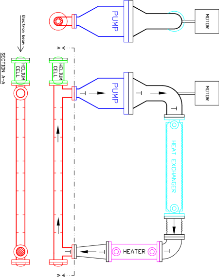
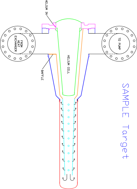
A key problem is handling the heat deposited in the hydrogen by the muon beam. As shown in Table 1, this can exceed 100 watts per absorber. LH2 targets have been successfully operated in such a heat-deposition regime, notably the target for the SAMPLE experiment at Bates [9]. These high-power target designs have followed the approach developed at SLAC [10], in which the liquid is pumped around an external cooling loop (see Fig. 1). The loop includes a heat exchanger, within which the deposited heat is transferred to a supply of cold helium gas, as well as a heater for fast regulation of temperature. The difficulty in such designs is assuring flow of the LH2 within the absorber cell that is predominantly transverse to the beam direction, since any little parcel of LH2 that flowed along the beam would be quickly heated above the boiling point. In the SAMPLE target (Fig. 1b) transverse flow was accomplished using a specially-designed perforated baffle, and for the proposed SLAC Experiment 158 target (Fig. 1a) the use of asymmetrically-perforated screens is under investigation [12]. We are developing a design in which transverse flow within the absorber cell is produced by variously-angled nozzles placed around the periphery.
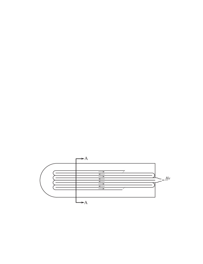
In addition to the external-loop approach, we are considering as an alternative heat exchange internal to the absorber vessel, using driven convection to provide mixing and transverse flow (Fig. 2). This has the obvious virtue of fewer moving parts. Moreover, the transverse flow arises naturally, rather than being imposed by a clever but complicated design. The key question is whether there will be sufficient convection at the anticipated power level to give the necessary rate of heat exchange via the cooling tubes at the periphery of the cell. We are addressing this by a series of computational-fluid-dynamics (CFD) calculations that numerically solve the Navier-Stokes equation on a suitable two-dimensional222Given the deflection of the absorber windows (discussed below) a three-dimensional calculation would be preferable but is impractical for any reasonable amount of computing resources. grid to evaluate the Nusselt number (the dimensionless parameter that characterizes the rate of convective heat transport) vs. the Rayleigh number (the dimensionless parameter, proportional to the power dissipation, that characterizes the degree of turbulence). Preliminary indications are that there will be sufficient convection; this will be investigated further numerically and tested experimentally on the bench.

4 Absorber windows
The thickness of the absorber windows is a critical parameter. They must be thick enough to sustain the pressure from the LH2, yet as thin as possible so as to minimize multiple scattering. The window thicknesses in Table 1 have been chosen based on the ASME standard for pressure vessels [7]. This choice also satisfies the Fermilab safety code for liquid-hydrogen targets [8]. As illustrated in Fig. 3, ASME [7] specifies three standard window profiles: hemispherical, ellipsoidal, and torispherical. The minimum thickness required in each case is
| (2) | |||||
| (3) | |||||
| (4) |
where is the pressure differential, the radius of curvature (for hemispherical windows), the length of the major axis (for ellipsoidal or torispherical windows), i.e. the absorber diameter, the maximum allowable stress, and the weld efficiency. In the above equations we give also , the sagitta of the window at its center, which determines which window shapes can be used for absorbers of given dimensions: since each absorber has two windows, the absorber length must satisfy . (Note that for ellipsoidal windows the ASME code considers only the case where the length of the major axis is twice that of the minor axis, and for the torispherical case the radius of curvature of the “knuckle” is 6% that of the main cap; see Fig. 3.) The maximum allowable stress is the smaller of (ultimate stress)/4 or (yield stress)/1.5 [8]. In practice we find that it is the ultimate stress that is the limit.

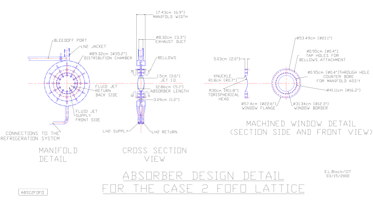
The hemispherical window shape minimizes the needed thickness. However, a hemispherical window is practical only for absorbers whose length exceeds their diameter. Since our absorbers are typically wider in diameter than they are long, we choose either the ellipsoidal or torispherical window profile. As an example, we show in Fig. 4 the mechanical design for the “FOFO1” absorber of Table 1. Given the 15 cm radius of the absorber, both hemispherical and ellipsoidal windows are ruled out. Torispherical windows with 5.1 cm sagitta leave just 2.4 cm for the flange and manifold assembly that joins the two windows and connects to the hydrogen inlets and outlets. Our solution is to machine each window with an integral flange out of a single block of material. The two flanges bolt together in “clamshell” fashion to form the manifold.
In the Neutrino Factory Feasibility Study [5] we consider FOFO and Single-Flip options for the cooling channel. In both designs the cooling performance is significantly limited by scattering in the absorber windows. To minimize this effect we propose to operate the absorbers at 1 atm pressure.333Operation of high-power LH2 absorbers at 1 atm pressure is not an established technique, 2 atm having been used in previous high-power target designs [9, 10, 11]. There may be safety concerns that will prevent such operation [13]; this is a topic for R&D. In the Single-Flip design the absorbers are long enough to permit the use of 300 m ellipsoidal windows.44footnotemark: 4 In the FOFO design two cooling sections are used having two different absorber sizes. In the first (“FOFO1”) section, 400 m torispherical windows are used as discussed above.44footnotemark: 4 By the second section, the beam has become small enough to permit a reduction in absorber diameter, allowing use of 200 m ellipsoidal windows.444We assumed a weld efficiency in specifying these window thicknesses, however in the integral-flange approach discussed above, , allowing 10% thinner windows, or alternatively, operation at 1.1 atm with the thicknesses given. The reduction in window thickness results in a lowering of the equilibrium emittance from 2.6 to 2.2 mmrad and a corresponding increase in the cooling rate.
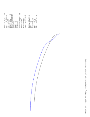
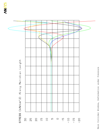
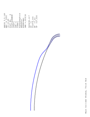
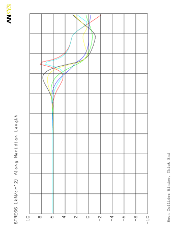
We have also begun to explore the option of customizing the thickness profile of the window in order to minimize the thickness at the center while maximizing strength. An ANSYS finite-element calculation has been carried out that shows that the stresses in a torispherical window are greatest near the edge, in the region in which the window curvature under pressure exhibits a point of inflection (Fig. 5). By thickening the material near the edge one can reduce the maximum stresses substantially, allowing the material near the center to be thinner by perhaps as much as a factor of 5. Of course manufacturability will also impose a limit on how thin the center of a machined window can be; we will explore this soon by building and testing prototypes.
5 R&D issues
Beryllium or AlBeMet (a composite of 62% beryllium/38% aluminum) could reduce the impact of the windows on the cooling performance. However, based on the CEA bubble-chamber accident, beryllium is believed to be incompatible with liquid hydrogen, and an R&D program will be required to establish safe design parameters for these materials. With 40% greater strength than aluminum and 2.1 times the radiation length, AlBeMet has the potential to lower the total radiation-length fraction per absorber from 2.4% to 1.8% or less, depending on the detailed optimization of absorber dimensions. (While beryllium windows may also be feasible, there may be little additional gain in going beyond AlBeMet.) Other cooling scenarios (e.g. SFOFO) use absorbers that are thicker compared to their diameter. Here effects of windows on cooling performance are reduced, and aluminum windows may be adequate. Whether R&D on exotic window materials is worthwhile may thus depend on which cooling approach prevails.
In all scenarios the specific power dissipation in the absorbers is large and represents a substantial portion of the cryogenic load of the cooling channel. Handling this heat load is a significant design challenge. An R&D program is already in place at IIT to understand the thermal and fluid-flow aspects of maintaining a constant temperature within the absorber volume despite the large spatial and temporal variations in power density. This program is beginning with CFD studies and is planned to proceed to bench tests and high-power beam tests of absorber prototypes over the next year.
In some scenarios (especially those with emittance exchange), lithium hydride (LiH) absorbers may be called for. Since it is a solid, LiH in principle can be fabricated in arbitrary shapes. In emittance-exchange channels, dispersion in the lattice spatially separates muons according to their energies, whereupon specially shaped absorbers can be used to absorb more energy from muons of higher energy and less from those of lower energy. However, solid LiH shapes are not commercially available, and procedures for their fabrication would need to be developed. Such an effort is challenging since LiH reacts with water, releasing hydrogen gas and creating an explosion hazard.
6 Acknowledgements
We thank M. Boghosian of IIT who carried out the CFD calculations and Z. Tang of Fermilab who carried out the ANSYS window calculations. This work was supported in part by the U.S. Dept. of Energy, the National Science Foundation, and the IIT Research Institute.
References
- [1] D. Neuffer, in Advanced Accelerator Concepts, F. E. Mills, ed., AIP Conf. Proc. 156 (American Institute of Physics, New York, 1987), p. 201.
- [2] R. C. Fernow and J. C. Gallardo, Phys. Rev. E 52, 1039 (1995).
- [3] C. Ankenbrandt et al., Phys. Rev. ST Accel. Beams 2, 081001, 1–73 (1999).
- [4] D. M Kaplan, “Muon Collider/Neutrino Factory: Status and Prospects,” IIT-HEP-99-3, FERMILAB-CONF-00-019, physics/0001037, to appear in Nucl. Instrum. Meth. (2000).
- [5] N. Holtkamp et al., “A Feasibility Study of a Neutrino Source Based on a Muon Storage Ring,” FERMILAB-PUB-00-108-E (2000), submitted to Phys. Rev. ST Accel. Beams.
- [6] V. Balbekov, E. Kim, G. Penn, et al., various MUCOOL Notes; see http://www-mucool.fnal.gov/notes/notes.html.
- [7] “ASME Boiler and Pressure Vessel Code,” ANSI/ASME BPV-VIII-1 (American Society of Mechanical Engineers, New York, 1980), part UG-32.
- [8] “Guidelines for the Design, Fabrication, Testing, Installation and Operation of Liquid Hydrogen Targets,” Fermilab, Rev. May 20, 1997; J. Kilmer, private communication.
- [9] E. J. Beise et al., Nucl. Instrum. Meth. A378 (1996) 383.
- [10] J. W. Mark, SLAC-PUB-3169 (1984) and references therein.
- [11] R. W. Carr et al., SLAC-Proposal-E-158, July 1997.
- [12] R. W. Carr et al., “E158 Liquid Hydrogen Target Milestone Report,” http://www.slac.stanford.edu/exp/e158/documents/target.ps.gz (April 21, 1999).
- [13] J. Kilmer, private communication.