SUPPRESSION OF BEAM BREAKUP INSTABILITY IN A LONG TRAIN BY INTRODUCING ENERGY SPREAD BETWEEN THE BUNCHES††thanks: Work supported by DOE contract DE-AC03-76SF00515.
Abstract
Interaction between the bunches in the NLC main linac via long range wakefields can cause a beam breakup instability. Although the magnitude of the long range wakefields for an ideal NLC structure is below the instability threshold, the wake increases when structure manufacturing errors are taken into account. In case of large errors, the developing instability can result in the projected emittance dilution of the bunch train. To suppress the instability, we propose to introduce an energy spread between the bunches, similar to the BNS energy spread for damping of the beam breakup within a single bunch [1]. Based on simple estimates, we show that the energy spread of order of 1-2% should be enough for suppression of the instability. The results of computer simulations with the simulation code LIAR confirm theoretical estimates and indicate that both the tolerances for structure misalignments and the incoming beam jitter can be considerably loosened by introducing the energy spread within the beam.
1 Introduction
Interaction between the bunches in the NLC linac via the long range wakefields can cause a beam breakup instability [2], similar to the beam breakup within a single bunch that is caused by short range wakes [3]. This instability, if severe, imposes tight tolerances on the beam injection errors as well as structure misalignments in the lattice.
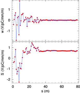
An example of the the long-range wake for the NLC structures is shown in Fig. 1. This wake was calculated assuming a random frequency error of the dipole mode in the structure with the rms spread of 3 MHz [4]. Note that in contrast to the short-range wakefield, that can usually be approximated by a linear function, the long-range wake is a complicated oscillating function of the bunch position.
One can try to estimate the projected normalized emittance growth of a train of bunches caused by randomly misaligned structures in the linac using the result of Ref. [5] for the expectation value of
| (1) |
where is the rms structures offset in the linac, is the classical electron radius, is the number of particles in the bunch, is the average value of the beta function at the beginning of the linac, is the number of structures in the linac, is the length of the structure, and are the initial and final relativistic factors of the beam, and is the sum wake. The -th component of is defined as a sum of the transverse wakes generated by all bunches preceding the bunch number (with ),
| (2) |
The quantity is the difference between and the average value , , with
| (3) |
where is the number of bunches. Eq. (2) is derived assuming a lattice with the beta function smoothly increasing along the linac as . Note that Eq. (2) is only valid if there is no beam break up instability, and hence gives a minimal emittance growth for given misalignment.
For the wake shown in Fig. 1, V/pC/m/mm. Using the nominal NLC parameters: , m, , m, GeV, GeV, and assuming m one finds m, which is about 1% of the nominal beam emittance at the beginning of the linac, m.
However, computer simulations for this case with the wake shown in Fig. 1 demonstrate the projected emittance growth in the train of order of 50%, (see Fig. 2), that is much larger than the above estimate. The reason for such large emittance dilution is the development of the beam breakup instability due to the long-range wakefields in the bunch train reflected in quasi-exponential growth in Fig. 2.
To suppress the instability, one can try to introduce an energy spread in the train of bunches [6], similar to the energy spread within a bunch that is routinely use for the BNS damping of a single bunch beam breakup.
2 Estimate of Required Energy Spread
To obtain a rough estimate of the energy spread required to suppress the long range beam break up instability, we use the autophasing condition for the BNS damping in the two-particle model for a FODO lattice [7, 8]
| (4) |
where is the relative energy difference between the particles, is the number of particles in the macroparticle, is the transverse wake, is the beam energy, is the betatron phase advance per cell in the FODO lattice, and is the cell length. The value of given by Eq. (4) would be enough for suppression of the beam break up instability between the two macroparticles with the interaction characterized by the wake .
To apply Eq. (4) for a train of bunches, we use the rms value of the wake shown in Fig. 1, V/pC/m/mm. The quantity from Eq. (4) was calculated for the NLC lattice as a function of distance , see Fig. 3. For the estimate, we use the average value of m2/GeV.
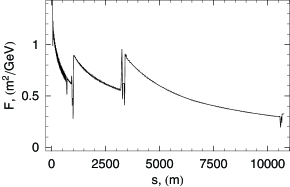
Finally, we need to relate the quantity to the energy spread in the train. Since Eq. (4) was derived for two macroparticles, one can expect that refers to the energy difference between the adjacent bunches in the train. Hence, the required energy spread in the train for suppression of the instability is equal to multiplied by the total number of bunches in the train, . We can now estimate as , which gives
| (5) |
This should be compared with the energy spread of the order of 1% within the bunch introduced for the BNS damping of the short-range beam breakup instability.
A more detailed theory of the beam breakup instability in a train with the energy chirp can be found in Ref. [9].
3 Computer Simulations
We carried out computer simulations using LIAR code [10] with variable energy spread in the train for the wake shown in Fig. 1. In these simulations, the bunches were treated as macroparticles to suppress the effect of short range wakefields.
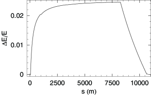
We used two types of energy profiles in the train. In the first case, the energy in the train varied linearly so that , where is the bunch number in the train, and is the energy slope. The rms energy spread in the train in this case is . An example of the profile of along the linac is shown in Fig. 4 — the energy spread was generated at the beginning of the linac, and taken out at the end, so that the final energy spread was close to zero. We also used an exponential energy profile in the train with the same functional form of the rms as shown in Fig. 4.

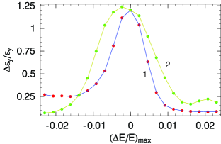
In the first set of simulations, all structures were randomly misaligned with rms value of 10 m. The energy spread in the train varied by scaling the profile shown in Fig. 4 and the final effective emittance of the train was calculated as a function of the maximum rms energy spread (approximately at m). The result is shown in Fig. 5. Positive values of correspond to the BNS-like energy profile, when the energy decreases toward the tail of the bunch and negative values of correspond to the opposite slope of the energy profile. As we see, the positive values of are more effective in suppression of the emittance growth.
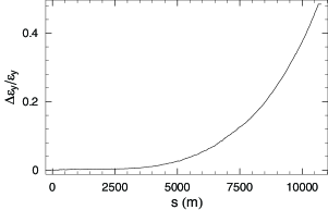
In the second set of simulations, the train was initially offset by 1 m (with all structures and quadrupoles perfectly aligned). The resulting emittance growth of the beam as a function of is shown in Fig. 6. Again, we see that the energy spread of the order of 1% results in much smaller emittance growth then for the bunches with the same energy.
4 Discussion
An energy spread between the bunches in the NLC is naturally generated in the linac by the beam loading effect. A special compensation scheme in the present NLC design will correct the energy spread to a minimal value. With a slight modification of the compensation scheme, it should also able to introduce a small controllable energy spread required for the long-range BNS damping, as studied in this paper. Another option of generating the energy spread between the bunches is using RFQ magnets.
5 Acknowledgements
The author thanks T. Raubenheimer for useful discussions.
References
- [1] V. E. Balakin, A. V. Novokhatsky and V. P. Smirnov. Proc. International Conference on High-Energy Accelerators, Batavia, 1983, pp. 119-120, 1984.
- [2] K. Thompson and R. D. Ruth, Phys. Rev., D41, 964 (1990).
- [3] A. W. Chao, B. Richter and C. Y. Yao, Nucl. Instrum. Meth., 178, 1 (1980).
- [4] Wakefield for RDDS1 C Incl HOM Ref and 4 Cells Decoupled computed by R. Jones.
- [5] K. L. Bane, C. Adolphsen, K. Kubo and K. A. Thompson, SLAC-PUB-6581, Presented at 4th European Particle Accelerator Conference (EPAC 94), London, England, 27 Jun - 1 Jul 1994.
- [6] G. V. Stupakov, NLC note LCC-0027, SLAC, September 1999.
- [7] A. W. Chao, Physics of Collective Beam Instabilities in High Energy Accelerators (Wiley, New York, year1993).
- [8] NLC ZDR Design Group and NLC Physics Working Group. Physics and technology of the next linear collider: a report submitted to Snowmass ’96, SLAC-R-0485, 1996.
- [9] C. L. Bohn and K.-Y. Ng. Paper MOA01, these Proceedings.
- [10] R. Assmann et al. SLAC-AP-103, SLAC, April 1997.