Monte Carlo study of the scattering error of a quartz reflective absorption tube
Abstract
A Monte Carlo model was used to study the scattering error of an absorption meter with a divergent light beam and a limited acceptance angle of the receiver. Reflections at both ends of the tube were taken into account. Calculations of the effect of varying optical properties of water, as well as the receiver geometry, were performed. A weighting function showing the scattering error quantitatively as a function of angle was introduced. Some cases of the practical interests are discussed
In Press: Journal of Atmospheric and Oceanic Technology, 2000
1 INTRODUCTION
Light absorption is the essential element required for marine phytoplankton growth. The region of the upper ocean illuminated by sunlight is responsible for most of marine primary production. Absorption and scattering of phytoplankton control the light field (at least for Case 1 waters which comprise a large majority of ocean waters), and thus, affect the spectral reflectance of the ocean surface. Such spectral changes provide information about ocean color (Gordon and Morel, 1983)
In all radiative transfer modeling of the marine environment the inherent optical properties (IOPs) are either the necessary input parameters, or in the case of inverse problems, the output of the calculations. This makes them important in marine optics studies. The measurement of the attenuation coefficient is relatively easy; an attenuation meter consists of a collimated light source and a collimated light detector at a known distance. The only major problem in the attenuation measurement are photons from outside sources or the ones reflected on the instrument scattered into the light beam, causing an underestimation of the attenuation coefficient value. The detector has a finite aperture so that some of the forward scattered photons will be counted as part of the direct beam, also causing an underestimation. However, the measurement of the components of the attenuation, the absorption and scattering coefficients, is inherently much more difficult, and researchers have been striving to minimize the measurement errors of these parameters for most of this century.
The central idea behind any absorption measurement is to project a beam of light through an absorbing medium. If one could measure all of the unabsorbed light of the direct beam, as well as all of the scattered light, the only light lost would be the absorbed light. Thus, absorption meters tend to be arranged to collect as much of the scattered light as possible. The absorption coefficient measured in any optical device has two major sources of error, both of which are due to the fact that natural suspensions tend to scatter light as well as absorb it. In practice, the scattered light traverses a longer path through the absorbing medium and so is more likely to be absorbed (the path length amplification factor). Secondly, not all of the scattered light is collected due to the geometry of the absorption meter (the scattering error).
One of the choices to measure in situ absorption is the cylindrical reflection tube. Such a tube needs to be be long enough to provide a sufficient optical path to measure the low absorption values typical for Case1 waters below 580nm. Any photon scattered forward off the instrument axis is, at least in theory, reflected by the tube walls until it reaches the detector. An ideal instrument of this kind should also have a reflector inside of the source end to collect the backscattered photons.
The first working prototypes of such a device were developed by Zaneveld and co- workers (Zaneveld and Bartz, 1984; Zaneveld et al., 1990). One of the greatest problems of making a practical reflective tube is the reflectivity coefficient of the walls. A Monte Carlo study of the performance of a reflective tube absorption meter (Kirk, 1992) shows that the results quickly deteriorate with reflectivity decreasing from 100%. As it is virtually impossible to produce perfect reflecting walls, especially ones that would not deteriorate with prolonged use of the instrument, the concept of a quartz glass tube surrounded by air was proposed instead (Zaneveld et al., 1990). Assuming smooth surfaces of the tube, all photons encountering the wall at an angle to the wall surface smaller than the critical angle, , must be internally reflected. Therefore, a clean quartz reflection tube should collect all photons scattered in the angular range between and (if multiple scattering is neglected). However, the large losses of photons scattered at angles above are the main theoretical source of error for quartz tube absorption meters.
The Monte Carlo calculations by Kirk (1992) were conducted for a prototype absorption tube with an almost parallel light beam resembling the Wetlabs ac-9 absorption meter. The results showed that the relative error of absorption is always positive and increases linearly with the ratio of scattering to absorption. The error increases with decreasing wall reflectance and acceptance angle of the receiver. Another study by Hakvoort and Wouts (1994) used a Lambertian light source. In this case the absorption error decreases with the decreasing angle of photon acceptance. However, early prototypes of HiStar, the new Wetlabs spectrophotometer, has a diverging beam limited to . The receiving end of the tube is illustrated in Fig. 1. It consists of a Light Shaping Diffuser (LSD) in front of a lens. The fiber transmits light to a spectrometer. Such an arrangement results in a large receiving area which through the use of the LSD and the lens translates into the small acceptance angle needed by the spectrometer.
In this paper we take account of the reflections at both ends of the tube, that were neglected by previous studies of this kind. We also extend previous results by considering a more realistic arrangement, by introducing weighting functions that quantitatively show the scattering error as a function of angle, and by providing calculations for some cases of practical interest.
2 CALCULATION SETUP
The Monte-Carlo code used was adopted from the code written to determine the effects of self-shading on an in-water upwelling irradiance meter (Piskozub 1994). This is a forward Monte Carlo algorithm, meaning that the photons are traced in the forward direction starting from the light source. An absorption event ends a photon’s history. The low values of the optical depth inside the absorption tube make this approach comparatively efficient.
The absorption tube studied (called henceforth -TUBE) is a cylindrical shell of inner radius r=0.006 m and length d=0.23 m which corresponds to the dimensions of the HiStar quartz reflective tube (see Fig. 1). Thickness of the quartz wall is r=0.002 m. The indices of refraction used are 1.33 for water and 1.41 for quartz.
The photons inside the -TUBE are traced along their three dimensional trajectories. The scattering or absorption events inside the volume of the water sample are defined by inherent optical properties of the medium: the absorption coefficient of the medium a, scattering coefficient b, and the scattering phase function . Random numbers are used to choose whether a given photon traveling from point (x,y,z) towards direction will reach the wall or the end of the cylinder. Otherwise, it is assumed that the photon ends its trajectory inside the liquid medium, and the type of the event (scattering or absorption) is determined by comparing a random number to the single scattering albedo value. All random number used in the code are uniformly distributed in the open interval (0, 1).
We define the Cartesian coordinate system such that the axis of the tube is co-located with the z-axis, and the center of the source end of the tube defines the origin of the coordinate system. Therefore, is the angle between the photon direction and the tube axis and is the angle of projection of the photon direction onto the x-y plane. In every scattering event the new direction of the photon is chosen using the relevant phase function.
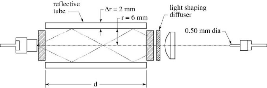
The source of photons is assumed to be within a circle of the radius r = 1.5 mm emitting photons into a cone of half-width. This represents the fiber head. The angular distribution of photons is assumed to be Lambertian up to the . The position of the photon entering the tube itself is calculated, taking into account the distance from the fiber head to the tube entrance (0.019 m) and refraction from air to water at the mouth of the reflective tube.
Such an -TUBE, defined above, is similar to the prototype WET Labs HiStar, but it does not precisely model the detailed radiance structure surrounding both the source and the receiver ends of the reflective tube. We believe that those details are of minor importance in comparison to neglecting the albedo of the tube ends. Therefore we introduced the albedo of the source end for photons returning to it from inside the tube, for which we estimated the albedo as 0.3 (0.2 being the diffuse albedo and 0.1 the specular albedo). This is a rough assumption of the combined effects of the input window and the silver colored metal surface around the fiber head.
The quartz walls are treated as ideally smooth, reflecting and refracting photons according to geometrical optics. The direction of a refracted photon is determined in the code by Snell’s law and probability of reflection and refraction by Fresnel’s law. However, no polarization effects are included. The photons are also followed inside the quartz, which is assumed to be non-absorbing. All photons leaving the outer surface of the quartz tube are treated as lost. The tube is assumed to be surrounded by an ideally black medium.
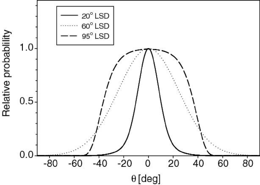
The receiver end of the tube is treated as a smooth surface reflecting 8% of the incident photons. This corresponds to the angular average of reflection for the glass window and the Light Shaping Diffuser (LSD) used. It is assumed that a photon hitting the diffuser plate at an angle reaches the receiver with a probability proportional to the angular diffusion distribution (or scattering angle profile) of the LSD. The Light Shaping Diffuser used in the instrument is a Physical Optics Corporation LSD. Also, we use in the calculations two other diffusers: LSD and LSDs. The angles are half-widths of the angular diffusion function. This means that, for example, a LSD has a 50% transmission efficiency at angle . The angular diffusion distribution used was determined by the least-square fits of the experimental curves provided by the producer. The LSD was approximated by two Gaussian functions (with all angles in degrees):
| (1) |
where , , . The LSD was approximated by a single Gaussian function:
| (2) |
where and . Finally, the LSD was approximated by a Gompertz function (Gompertz, 1825):
| (3) |
where , and .
The shapes of the three LSD diffusion angle profiles are presented in Figure 2.
The standard Petzold scattering phase function for open turbid waters was used (Petzold 1972) except for the calculations of the effect of the phase function shape on the measurement error where Henyey-Greenstein phase functions (Henyey and Greenstein, 1941) were used.
Each Monte Carlo calculation was performed twice: one to determine how many photons are recorded if there is no absorption and scattering () and the other for the IOPs (absorption, scattering and phase function) of the aquatic medium being studied (P). We define the measured absorption am as Kirk (1992):
| (4) |
where d is the length of the cylinder.
It must be noted that the first program run corresponds to calibration of the instrument in “ideal water,” not in air. We use the water index of refraction for this medium so as not to influence the new photon direction in refraction events. Therefore, the results are different from what one would obtain if the tube was filled with air. Such a non-scattering and non-absorbing liquid medium does not exist. However, it is the most obvious reference value to use in the calculations aimed at studying the calibration of the instrument, because it does not introduce any photon losses due to scattering (b=0) and does not change the behavior of photons on the quartz-liquid border.
3 RESULTS
3.1 SEMI-ANALYTICAL CONSIDERATIONS
In this section we present qualitative arguments related to the optical phenomena influencing the fate of photons in the absorption tube. The purpose of this is to provide approximate results that can be compared with exact Monte Carlo results later. The semi- analytic results give a better understanding of the underlying physics. If, for example, the IOPs of the studied water sample are assumed to be: b=0.8 m-1, a=0.2 m-1, and the Petzold San Diego Harbor (turbid water) phase function, one can expect that 4.5% () of all photons will be absorbed and 16.8% () will be scattered in the water volume inside the quartz tube.
The phase function used, determines that 92.9% of all scattering events take place in the 0-41∘ range. Assuming for simplicity, that before scattering, all photons traveled parallel to the tube axis, all those scattered photons will be reflected back into the tube on all encounters with the tube wall. Similarly, all photons backscattered into the range of 139-180∘ stay in the tube on their way back to the source end. These represent 0.3% of all photons. The remaining 6.8% of all scattered photons are scattered into the range 41-139∘. These photons have a large probability of leaving the tube on the first encounter with the wall. The angles to the z-axis at which those photons travel make it virtually certain that they will leave the tube before reaching either end, unless they are scattered close to . For example at , a photon scattered in the very center of the tube will hit the wall 9 times before reaching the end of the tube making the probability of not leaving it . The 6.8% of scattered photons that are lost translates into 1.1% of all traced photons being lost through the walls.
After the absorption and scattering losses are taken into account, 94.3% of all traced photons reach the receiver end of the tube. Thus, the assumption of 8% specular albedo of the receiver end of the tube means that 7.5% of all traced photons are reflected from the receiver end of the tube. Absorption and scattering losses result in only 7.1% of all initial photons coming back to the source end after being reflected. The backscattered photons, which are attenuated in a pathlength approximately equal to the tube length, increase this number to 7.2%.
Another important aspect of a quartz absorption tube is the length of the path that the photons travel in quartz instead of water. Any distance traveled in quartz decreases the attenuation due to the negligible absorption coefficient in the visible range of the spectrum (Kirk 1992). This decreases the measured absorption values because the receiver is reached by more photons due to the shorter path through the absorbing medium. In the studied tube geometry, the ratio of tube diameter to wall thickness is only 6:1, and considering that every time the photon goes across the water volume it needs to cross the wall twice (out and back into the tube) it would seem that this effect must be overwhelming. However, due to Snell’s law and the narrow angles between the direction of most photons and the wall, the average path of photons in quartz is much smaller.
3.2 SANITY CHECKS OF THE MONTE CARLO RESULTS
Even if rough approximations of the results are possible with simple arithmetic calculations, Monte Carlo modeling includes all optical phenomena taking place inside the tube. This can be illustrated by comparing the approximate values from the previous section to the results of a Monte Carlo run using 40 million photons with the same IOPs. The number of photons lost through the walls is 1.74% (estimated above as 1.1%). The discrepancy can be explained by the divergence of the input beam: photons entering the tube at an angle may leave it through the walls, even if scattered from its original direction at less than the angle of total internal reflection, resulting in higher scattering losses.
The Monte Carlo derived absorption losses percentage is 4.09% (semi-analytically estimated as 4.5%). The reason for this is that the path length of the photons is in quartz instead of in water. The Monte Carlo code makes it possible, by tracing each photon individually, to calculate the average path traveled by the photons in water to be 21.15 cm and in quartz: 2.83cm. This means that the path in water is 8% shorter than the length of the reflective tube, a value much higher than that calculated by Kirk (1992) for a parallel beam in which only the scattered photons encounter the walls. The losses by absorption on the front end of the tube are 4.84% of all photons (estimated as 5.0%). The small difference is the net result of smaller absorption losses and greater scattering losses.
The effect of the shortened optical path, described above, is not very grave if the way the instrument is calibrated is taken into account. All calibration techniques involve a comparison of the received signal (that is the number of photons reaching the receiver) for the measured sample with pure water or air values. Using pure water almost completely removes the error due to non-scattered photons traveling partly inside the wall, as the effect will be identical for water of any IOPs. Calibrating the instrument in air leaves some error due to path length in quartz because air has a different index of refraction making the path length in quartz shorter. There is, however, a much bigger source of error in calibrating the instrument without water, which is the removal of total internal reflection on the quartz wall by surrounding both its sides by the same medium.
3.3 VARIATION IN THE SCATTERING-ABSORPTION RATIO
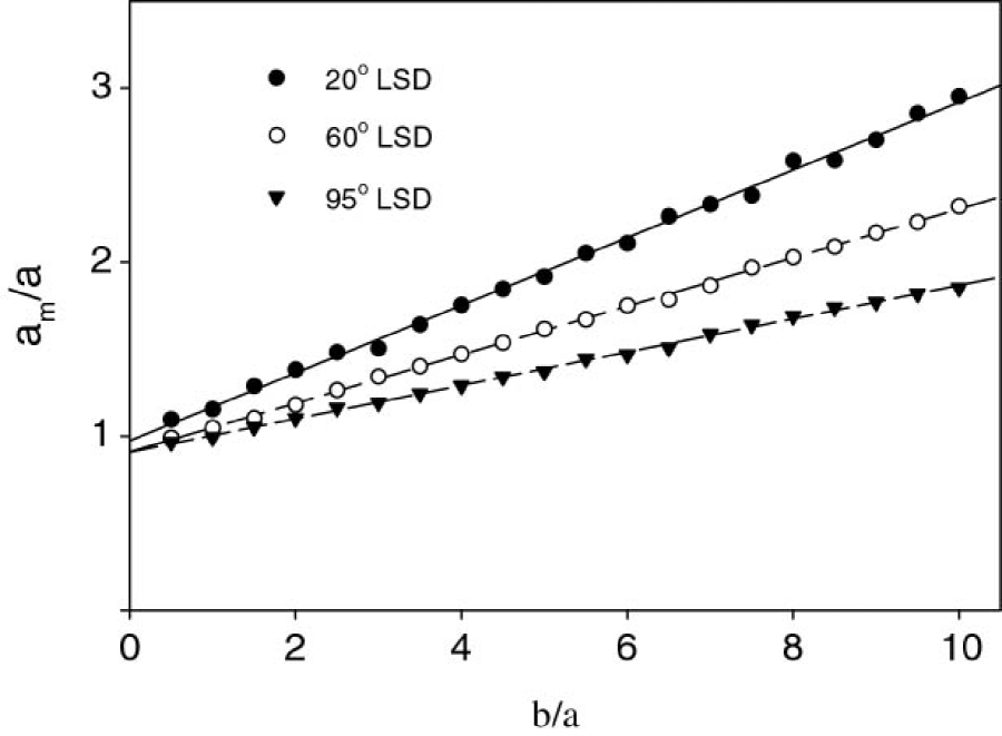
It was shown by Kirk (1992) that for a reflective tube absorption meter propagating an almost parallel beam, that the ratio of the measured to the true value of the absorption coefficient increases linearly with at a rate depending on the phase function used. We decided to test whether such a relationship will hold for the relatively divergent light beam and limited acceptance angle of the -TUBE. Figure 3 shows that this is indeed the case for all studied angles of acceptance (depending on the LSD type used). The slope coefficients w of the linear fit
| (5) |
are 0.194 for LSD, 0.139 for LSD, and 0.0957 for LSD. These results suggest that the scattering losses of the instrument increase with the decreasing angle of acceptance of the receiver. It must be noted that the values of the coefficient w depend on the scattering phase function used.
Figure 3 shows that there is a small offset in Equation 5. Its general version (where o is the offset) can be transformed to
| (6) |
which, for a given phase function and absorbing tube geometry, allows for determining the true a value if attenuation c is measured independently. The parameters w and o may be calculated for the given absorption meter geometry if the phase function is known at least approximately. The values of the coefficient w, for the physically important range of Henyey-Greenstein asymmetry parameter g and the LSD receiver are shown in Figure 4.
3.4 VARIATION IN THE SCATTERING PHASE FUNCTION
The measurement error in absorption depends on the scattering phase function of the aquatic medium (Kirk, 1992). To study the effect of the scattering phase function on absorption measured by the given instrument setup with LSD, we performed a sequence of Monte Carlo calculations for the Henyey-Greenstein phase function (Henyey and Greenstein 1941) by varying the asymmetry parameter g
| (7) |
where g is a parameter determining the shape of the phase function. In this paper we assume range of g from (isotropic scattering) to (forward scattering).

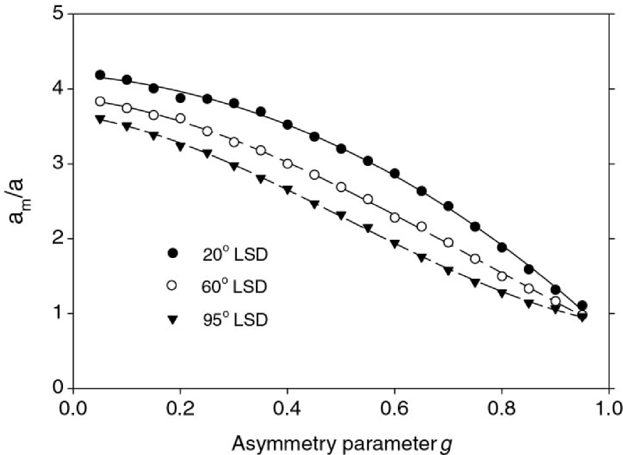
The results in Fig. 5 show as a function of the asymmetry parameter. They were obtained by running the code for the studied tube equipped with three different LSD plates (, , and ). As expected, for g approaching 1 the ratio is close to 1 as all photons are scattered almost in the direction that they were headed before the scattering. For a more realistic range of g values between 0.8 and 0.9 (Mobley, 1994) the measured absorption increases when g decreases due to the greater scattering losses of the photons. The value of for and LSD is not a statistical error, but the effect of the slightly longer path of scattered photons in the quartz, in comparison to the non-scattering ”ideal water” which results in decrease of absorption.
For small g values the values (Fig. 5) approach the maximum (a+b)/a at which all the scattered photons are lost and the measured value of absorption equals the total attenuation. In the case studied (a+b)/a = 5. However, even for an isotropic scattering phase function (g=0) the value of the scattering error does not reach this maximum value because some photons are scattered at angles small enough to be recorded by the receiver. Again, the figure shows that increasing the angle of acceptance of the receiver decreases the absorption error for all realistic phase functions.
3.5 VARIATION IN THE ACCEPTANCE ANGLE
Results presented by Kirk (1992) for a reflective tube absorption meter with an almost parallel beam show a rapidly increasing value of with the acceptance angle decreasing below . On the other hand, Hakvoort and Wouts (1994) suggest that for the reflective tube with Lambertian light source and metallic reflective walls, the measurement error increases with the acceptance angle of the receiver. The Monte Carlo code was run for several values of the receiver angle of acceptance to test if the similiar situation arises for the -TUBE. No Light Shaping Diffuser was used in this case. The results are presented in Figure 6.
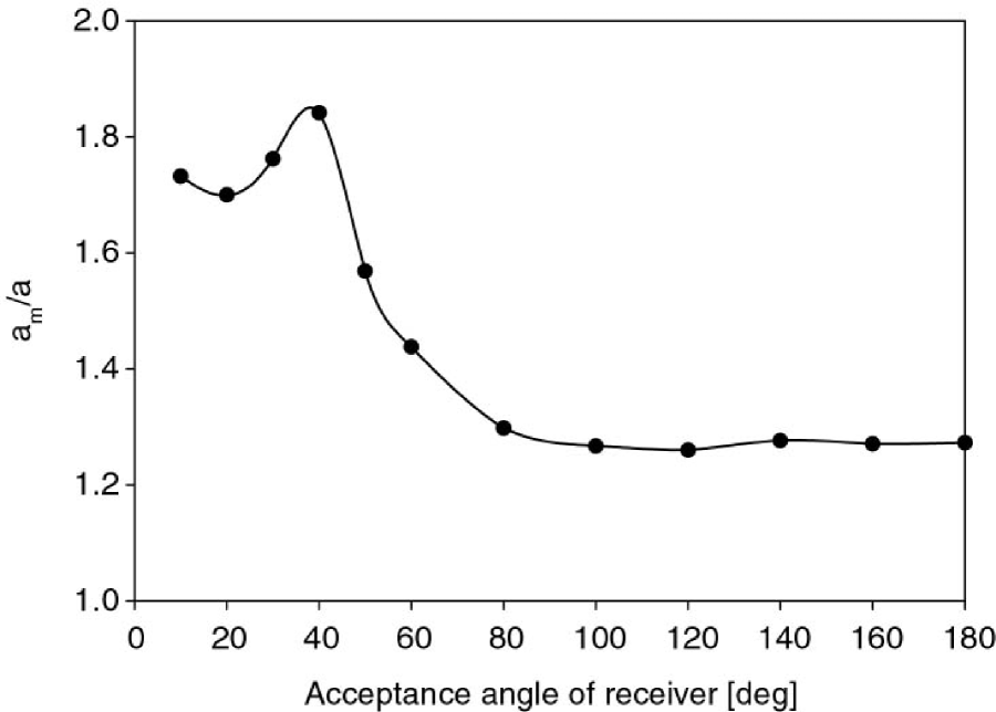
It can be seen that for large acceptance angles () the values have a similar shape to that of a parallel beam case. However, for acceptance angles in the range a minimum can be observed, instead of a high peak as in the case of a parallel beam. The reason for that is that the source beam is more divergent than the angle of acceptance. For small acceptance angles the receiver accepts some scattered photons that would not be accepted if they reached the receiver without a scattering event. This is because their angle of incidence is reduced by the scattering event. This reduces the scattering error of the absorption measurement. Unlike the Lambertian source case, there is no major increase of values for large acceptance angles (although a small increase above may be discerned). It should be noted that the LSD plate used in the instrument corresponds roughly to an acceptance angle of . Although this angle is close to a local minimum of , it is still within the range of the highest levels of absorption error.
3.6 ANGULAR FUNCTION OF PHOTON LOSS PROBABILITY
Full understanding of the mechanism of scattering loss is not possible without determining the angular relationship of the scattering error of the reflective tube absorption meter. The fraction of scattered light lost because of the absorption after being scattered at a given angle can be defined as a loss function . The angular integral of this function multiplied by the phase function is the error of the measured absorption value
| (8) |
The advantage of the W function is that it is not dependent on the shape of the phase function but only on the tube geometry. This is true only if multiple scattering is neglected because a second scattering event influences the fate of a photon already scattered. In order to differentiate among the possible sources of the scattering loss error of the absorption value we decided to calculate three variants of the W function (a) for scattering losses due to photons lost through the tube walls, (b) same as and for scattering losses due to additional photons absorbed by the source (”front”) end of the tube, (c) same as and for scattering losses due to additional photons lost on the LSD.
By ”additional photons” we mean that only the difference between the number of photons lost by the absorption and scattering and the ”ideal” water is taken into account. In each of the three cases the actual value of W for angle range is derived by dividing the number of photons scattered into the angular sector and subsequently lost by the sum of these photons plus the number of photons scattered into the same sector which are subsequently recorded by the receiver. Fig. 7 presents the W functions calculated by running the code for 40 million photons with , , Petzold turbid phase function, and LSD. In this case the number of multiple scattered photons is 7% of all which are scattered. That means that the influence of the phase function shape on the W function is of secondary importance. All three functions have the sigmoid shape for the forward scattered photons between . There is no sharp step at and because the divergence of the beam causes some photons to travel at an angle to the tube axis before scattering which allows photons to escape through the wall even if scattered at an angle smaller than the total internal reflection angle. On the other hand, a photon scattered at more than back towards the axis may survive the encounter with the wall without being refracted out of the tube. The symmetrical shape of is caused by the fact that losses on the ”front” end are not taken into account. A photon backscattered at angle has the same chance of being lost through the walls as the one scattered at . The symmetry is broken only by the assumed diffusive albedo of the light source end of the tube because some photons leave the tube by the wall after being diffused on its source end.
Adding the photon losses on the light source end of the tube (function ) changes the symmetry. Most of the backscattered photons are lost in this way as well as some of the forward scattered. The latter is caused by two reasons. Some forward-scattered photons are reflected by the receiver end of the tube back towards the source end. However, it is even more important that some of the forward scattered photons are absorbed on the ”front” end because they were scattered after they were reflected on the receiver end. The reverse direction of those photons before scattering complicates the function, but we decided to include these scattering events in the statistics used to calculate the functions because they contribute to the total scattering losses.
Receiver end losses are caused by more photons missing the receiver due to reaching it at a wider angle after a scattering event. This changes the picture by, paradoxically, decreasing the photon losses for photons that were scattered in the forward direction (function ). This means that scattering a photon by a small angle increases its probability of being accepted by the receiver compared to the average of non-scattered photons. This is caused again by the source beam being wider than the acceptance angle of the receiver. The discrepancy between and , especially at scattering angles close to 0, is also partly caused by the inclusion of photons scattered on their way back to the source end of the tube. One of its consequences is that the population of photons scattered at close to 0 degree is different from the population of non-scattered photons.
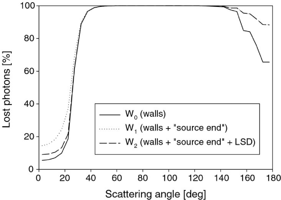
The shape of the W functions for angles greater than is not important for the scattering error estimates because only a fraction of all the photons is backscattered. For the function which includes all the photon losses due to scattering, the loss of backscattered photons is close to 100%. Therefore, the best fit approximations to , and were calculated for the range only. The three functions were fitted with a 4-parameter sigmoid
| (9) |
where for we have A = 0.935, , , , for we have , , , , and for we have , , , .
4 CONCLUSIONS
Monte Carlo calculations of the scattering error for the HiStar prototype absorption meter show that the different blueprint of the instrument (more divergent light beam and a limited angular view of the receiver) in comparison to other reflective tube absorption meters does influence the error. Due to additional scattering losses by the view limited receiver the absorption error is greater for all combinations of moderate optical parameters. It is possible to correct the error by careful calibration, and the results presented in this paper for the turbid water Petzold phase function are a step in this direction. Independent measurements of attenuation may improve the error correction for water samples of known (at least approximately) phase functions as shown in the paper. However, the source of inter-instrumental discrepancy in absorption measurement that is more difficult to correct is their different responses to phase function variability. One possible solution is to use the photon loss function W. If the phase function of the studied sea-water is known (or is possible to be estimated by comparing it to known phase functions of similar water samples), the W function makes it possible to calculate directly the value of the scattering error for the sample.
Our calculations show that the main source of the absorption error is the view limited receiver. Therefore, we suggest that if technically possible (it would diminish the amount of light collected by the receiver optical fiber) a diffuser of wider angular characteristics should be used in the instrument receiver setup.
5 REFERENCES
Bricaud A., Babin M., Morel. A., and Claustre H., 1995:
”Variability in the chlorophyll- specific absorption coefficients
of natural phytoplankton: analysis and parameterization,” J.
Geophys. Res. , 100, 13321–13332.
Gompertz B., 1925: ”On the Nature of the Function
Expressive of the Law of Human Mortality,” Phil. Trans. Roy. Soc.
London., 115, 513.
Gordon H. R. and Morel, A. 1983: ”Remote assessment of
ocean color for interpretation of satellite visible imagery, a
review” in Lecture notes on coastal and estuarine studies, vol.
4, Springler Verlag, New York, 114pp.
Hakvoort J.H.M, Wouts R. 1994: ”Monte Carlo modelling of
the light field in reflective tube type absorption meter,” Proc.
SPIE , 2258, Ocean Optics XII, 529–538.
Henyey, L. G., and J. L. Greenstein, 1941: ”Diffuse
radiation in the galaxy,” Astrophys. J., 93, 70–83.
Kirk, J.T.O, 1992: ”Monte Carlo modeling of the
performance of a reflective tube absorption meter,” Appl. Opt.,
31, 6463–6468
Mobley, C. D., 1994, Light and water: radiative transfer
in natural waters, Academic Press, San Diego.
Petzold, T. J., 1972: ”Volume scattering functions for
selected ocean waters,” SIO Ref. 72-78, Scripps Institution of
Oceanography, Univ. of California, San Diego.
Piskozub J., 1994: ”Effects of surface waves and
sea-bottom on self-shading of in-water optical instruments” in
Ocean Optics XII, Proc. SPIE, 2258, 300–308.
Pope R.M., Fry E.S., 1997: ”Absorption spectrum
(380-700 nm) of pure water. II. Integrating cavity measurements,”
Appl. Opt., 36, 8710–8723.
Zaneveld J.R.V, Bartz R, 1984: ”Beam attenuation and
absorption meters” in Ocean Optics VII, M.A. Blizard ed., Proc.
SPIE, 489, 318–324.
Zaneveld J.R.V, Bartz R., Kitchen J.C, 1990: ”A reflective tube absorption meter,” in Ocean Optics X, R.W. Spinard ed., Proc. SPIE, 1302, 124-136.