Fusion Hindrance and the Role of Shell Effects in the Superheavy Mass Region
Abstract
We present the first attempt of the systematical investigation about the effects of shell correction energy for dynamical processes, which include fusion, fusion-fission and quasi-fission processes. In the superheavy mass region, for the fusion process, the shell correction energy plays a very important role and enhances the fusion probability, when the colliding partner has strong shell structure. By analyzing the trajectory in the three-dimensional coordinate space with a Langevin equation, we reveal the mechanism of the enhancement of the fusion probability caused by shell effects.
Keywords:
Superheavy elements, fluctuation-dissipation dynamics, fusion-fission process, quasi-fission process:
24.60.Ky, 27.90.+b1 Introduction
In the heavy ion fusion reaction, with increasing atomic numbers of the target and the projectile, it becomes more difficult to make a compound nucleus due to the strong Coulomb repulsion force and strong dissipation force. In the superheavy mass region, this difficulty is more remarkable. Though the mechanism of fusion-fission reaction in the heavy mass-region is not clear, generally we recognize the existence of fusion hindrance.
The fusion hindrance is mainly caused by the macroscopic properties of the colliding partner. On the contrary, the fusion is enhanced by the shell structure of the nuclei moll97 ; armb99 . In the experiments, especially cold fusion reaction, these advantages are used to synthesize the superheavy nuclei hofm00 ; mori03 . To understand the fusion mechanism clearly, it is better to treat separately the fusion hindrance and the fusion enhancement, that is to say, the macroscopic aspect and the microscopic one.
In our previous study ari05I , we have discussed the fusion hindrance in the superheavy mass region. We presented the origin of the fusion hindrance systematically by the trajectory calculation. In the present paper, as fusion enhancement, we focus on the influence of shell effects. It is known that the nuclear structure of the projectile-target combinations correlates to the touching probability sato02 ; ikez03 , but it influences also the dynamics from the touching point to the compound nucleus. We investigate precisely how the trajectory behavior is influenced by the shell correction energy.

2 Model
Using the same procedure as described in reference ari04 , we investigate the dynamical processes. The fluctuation-dissipation model with the Langevin equation is employed. We adopt the three-dimensional nuclear deformation space given by two-center parameterization maru72 ; sato78 . The three collective parameters involved in the Langevin equation are as follows: (distance between two potential centers), (deformation of fragments) and (mass asymmetry of the colliding nuclei); , where and denote the mass numbers of the target and the projectile, respectively.
The multidimensional Langevin equation is given as
where a summation over repeated indices is assumed. denotes the deformation coordinate. is the conjugate momentum of . is the potential energy, and and are the shape-dependent collective inertia parameter and dissipation tensor, respectively. A hydrodynamical inertia tensor is adopted in the Werner-Wheeler approximation for the velocity field, and the wall-and-window one-body dissipation is adopted for the dissipation tensor. Details are explained in reference ari04 .
3 Results
3.1 Effect of the Cold Fusion Valleys in Fusion Process
Figure 1 shows the potential energy surface of the liquid drop model (a) and with shell correction energy (b) for in the space , which is calculated by the two-center shell model code suek74 ; iwam76 . When we consider the shell correction energy, we can see the pronounced valleys which lead to the compound nucleus. The valleys are called ’cold fusion valleys’ gra99 ; gra00 . It is said that these valleys enhance the fusion probability. We discuss the effect of the cold fusion valleys in the dynamical process using the trajectory calculation.
As our first attempt, in the dynamical calculation, we employ the potential energy of the liquid drop model with the full shell correction energy, which corresponds to the potential energy surface at the nuclear temperature MeV. It is represented by , or . We compare the fusion probability with the different injection points, where the shell correction energy has remarkably negative and positive values like and , that correspond to the reaction 76Ge + 208Pb and 108Ru + 176Yb, respectively.
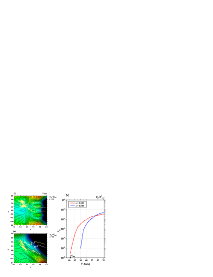
Figure 2(a) shows the sample trajectories which are projected onto the plane of . The contact point is marked by . The light yellow line denotes the trajectory with the starting point at the incident energy which corresponds to the excitation energy of the compound nucleus =20 MeV. This trajectory looks to move along the valley till . Then it enters the region near . On the other hand, the trajectory with the starting point goes till without changing the mass asymmetry parameter , which is denoted by the white line. It seems that the trajectory overcomes the mountain located at . We project these trajectories onto the plane at in Fig. 2(b). The trajectory with the starting point can enter around the compact shape region, but it is not trapped by the pocket around the ground state. The trajectory with the starting point moves quickly in the direction and goes to the fission region. We can say, the former is a deep quasi-fission process (DQF) and the latter is a quasi-fission process (QF) ari04 ; ari05I .
Figure 2(c) shows the fusion probability with the initial value and , which are denoted by the red and blue lines, respectively. The potential energy at the contact point with is lower than that with , due to the shell correction energy. Therefore, at low excitation energy, the former fusion probability is larger than the latter one, because in the former case the available kinetic energy at the contact point is larger than in the latter case. The arrow denotes the Coulomb barrier bass74 .
3.2 Evolution of the Cold Fusion Valleys in the Dynamical Process
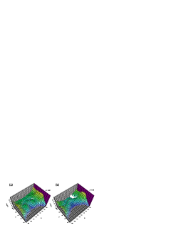
Usually the cold fusion valleys are discussed using the potential energy surface on the plane with , like as Fig. 1(b). However, in the dynamical process, the trajectory moves in the large direction. We should discuss the cold fusion valleys with the dynamical evolution of the parameter. For the case, which corresponds to Fig. 1(b), we can see the remarkable the cold fusion valleys. With changing value in the dynamical process, the cold fusion valleys also changes, which is shown in Fig. 3. When the changes about 0.4, the cold fusion valleys disappear.
3.3 The Role of Shell Effects in the Fusion Process
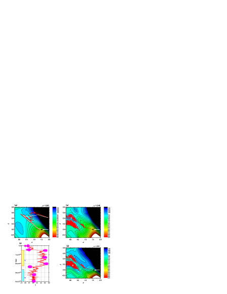
With the shell correction energy, we discuss another important effect to enhance the fusion probability. In the discussion on fusion hindrance ari05I , we indicated that the turning point is important. Fig. 4(a) shows the potential energy surface of for =102 at the turning point on the plane, that is to say, corresponds to the value at the turning point. The mean trajectory is denoted by the white line. The gray line denotes the trajectory with taking into account the fluctuation. At the turning point , the trajectory moves to the fission direction due to the potential landscape.
On the other hand, when we take into account the shell correction energy in Fig. 4(c), the temporary pocket appears at the turning point (indicated by ). At in Fig. 4(d), the pocket (indicated by ) corresponds to the ground state. When we take into account the shell correction energy, the trajectory is trapped in the pocket at the turning point, and is blocked from going to the fission area ari05 . During the stay in the pocket , the mass asymmetry is relaxed. With appearing of the large pocket at , the trajectory moves to the pocket . The pocket helps the trajectory to enter the region corresponding to the compound nucleus. Fig. 4(b) shows the time evolution of the nuclear shape. The horizontal axis denotes the . The trajectory moves in the large direction quickly, then it is trapped in the pocket . During the stay in the pocket , the mass asymmetry changes. With approaching the trajectory moves into the pocket . It corresponds to the compound nucleus.
The temporary pocket that appeared due to the shell correction energy enhances the fusion probability. As the further study, we take into account the temperature dependence of shell correction energy.
The author is grateful to Professor M. Ohta for his helpful suggestions and valuable discussion throughout the present work.
References
- (1) P. Möller, J.R. Nix, P. Armbruster, S. Hofmann, G. Münzenberg, Z. Phys. A356, 251 (1997).
- (2) P. Armbruster, Rep. Prog. Phys. 62, 465 (1999).
- (3) S. Hofmann and G. Münzenberg, Rev. Mod. Phys. 72, 733 (2000); S. Hofmann et al., Eur. Phys. J. A14, 147 (2002).
- (4) K. Morita et al., Nucl. Phys. A734, 101 (2004); K. Morita et al., Journal of the Physical Society of Japan, 73, 2593 (2004).
- (5) Y. Aritomo and M. Ohta, Nucl. Phys. A764, 149 (2006).
- (6) K. Satou, H. Ikezoe, S. Mitsuoka, K. Nishio, and S.C. Jeong, Phys. Rev. C65, 054602 (2002).
- (7) H. Ikezoe, K. Satou, S. Mitsuoka, K. Nishio, and S.C. Jeong, Phys. Atom. Nucl. 66, 1053 (2003).
- (8) Y. Aritomo and M. Ohta, Nucl. Phys. A744, 3 (2004).
- (9) J. Maruhn and W. Greiner, Z. Phys. 251, 431 (1972).
- (10) K. Sato, A. Iwamoto, K. Harada, S. Yamaji, and S. Yoshida, Z. Phys. A288, 383 (1978).
- (11) S. Suekane, A. Iwamoto, S. Yamaji and K. Harada, JAERI-memo, 5918 (1974).
- (12) A. Iwamoto, S. Yamaji, S. Suekane and K. Harada, Prog. Theor. Phys. 55, 155 (1976).
- (13) R.K. Gupta and W. Greiner, Heavy Elements and Related New Phenomena edited by W. Greiner and P.K. Gupta (World Scientific 1999) p. 397.
- (14) W. Greiner, Proc. of Fusion Dynamics at the Extremes, Dubna, 2000 (World Scientific 2000) p. 1.
- (15) R. Bass, Nucl. Phys. A231, 45 (1974).
- (16) Y. Aritomo and M. Ohta, Nucl. Phys. A753 152 (2005); nucl-th/0502042.