Hadron Blind Detector for the PHENIX Experiment at RHIC
Abstract
The PHENIX collaboration has designed a conceptually new Hadron Blind Detector (HBD) for electron identification in high density hadron environment. The HBD will identify low momentum electron-positron pairs to reduce the combinatorial background in the mass region below 1 GeV/c2. The HBD shall be installed in PHENIX during the 2007 physics run.
The HBD is a windowless proximity focusing Cherenkov detector with a radiator length of 50 cm, photocathode and three layers of Gas Electron Multipliers (GEM) for gas amplification. Pure serves both as a radiator and as a detector gas. The radiation budget of the device is less than 3% of a radiation length.
Keywords:
HBD; GEM; CsI photocathode; UV-photon detector; CF4:
29.40.-n; 29.40.Cs; 29.40.Ka; 25.75.-q1 Physics goal
The study of low-mass electron-positron pairs in Heavy Ion Collisions is a powerful tool to investigate properties of the newly discovered strongly coupled Quark Gluon Plasma. Results obtained by the NA45 and NA60 experiments at CERN na45 ; na60 show an excess of pairs produced in the mass region below 1GeV/c2. The PHENIX experiment at RHIC measured the low mass dilepton region phenix_dilept , however a detailed study of dileptons is very difficult without suppression of the combinatorial background coming from electron-positron pairs with small opening angle. Their primary source is the decays of mesons and -conversions. The main purpose of the PHENIX upgrade with the HBD detector is the rejection of close pairs by two orders of magnitude.
2 HBD Concept
An extensive simulation done for the HBD loi demonstrated that the only way to suppress the dilepton combinatorial background without loosing the signal requires electron identification. The rejection factor must be 100 with an electron detection efficiency of 90%. The HBD must cover solid angle 20% larger than the nominal PHENIX acceptance. Detectors based on Cherenkov radiation are the most effective choice to meet such requirements.
Cherenkov detector consists of a radiator in which particles shall follow straight trajectories. This competes with the high resolution tracking which benefits from the increase of the magnetic field. The PHENIX detector phenix has two magnetic field coils which allow to increase the magnetic field for better tracking or compensate it within the radius of 50-60 cm from the interaction point and keeping the initial angles of all tracks.
An important element of the classic Ring Imaging Cherenkov Detector is the focusing mirrors located at the end of the radiator. In PHENIX configuration the mirror cannot be used because of the geometrical constrains. Therefore it was decided to replace the mirrors with the light sensitive detectors placing them in the path of all particles produced in the collisions. The HBD detection unit thus must be sensitive to UV light and blind to all hadrons traversing it. It must also keep its radiation budget below 3% of the radiation length and fit into cm.
2.1 The photocathode and the gas
A crucial decision for the Cherenkov counter is the choice of the photo-sensor. Amid a variety of choices the only considered were those which fit the radiation length budget, i.e. solid film and gaseous/aerosol sensors. The second option, however, requires to separate radiator and amplification into two different gaseous volumes. It significantly increases the radiation length and besides that the window serves as an auxiliary source of Cherenkov radiation. The first option is preferable in spite of the same gas must be used as the Cherenkov radiator and the electron multiplication media.
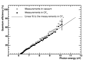
The most widely used film photocathode is the reaching 80% quantum efficiency (Q.E.) in extreme ultra-violet (E.U.V.) part of the spectra, see fig. 1. To match the photocathode Q.E. one has to use the gas which is transparent in the E.U.V. That limits the choice of gases to mixtures of carbofluorides and noble gases having the deepest E.U.V. cut-off wavelength. Among them the pure transparent up to 11.5 eV and with the refraction index of n=1.00062111depends on the photon energy, given value corresponds to visible light is considered the primary choice. Based on the R&D carried out during the development stage RandD the electrons can be effectively extracted into atmosphere with up to 85% efficeincy compare to vacuum (full symbols in fig. 1). The same parameter in pure of never exceeds 60%.
2.2 The amplification unit
The main challenge is to build a detector sensitive to the smallest possible charge produced by the Cherenkov photons and not sensitive to the much larger ionization coming from hadrons traversing it. The difference between the two processes is in the localization of the primary charges. In the first case they appear on the surface of the photocathode and in the second inside the gas volume. The detector concept utilizing primary charge localization was suggested by Y. Giomataris and G. Charpak giomataris in 1991. Electrons extracted from the photocathode surface undergo full amplification in a parallel plate detector whereas electrons produced inside the detector sensitive volume are only partially amplified. A prototype of such detector was built and studied by the group of T. Hemmick at Stony Brook University in 1996 tom .
The major problem with this approach are the avalanche photons shining back to the photocathode. Since the gas used in the detector is the same gas as used in the radiator no admixtures can be used to quench the feedback. The advent of the new detector, the Gas Electron Multiplier (GEM), invented by F.Sauli in 1997 sauli made it possible to overcome this difficulty. Among other features of the GEM is that the photon feedback is blocked by geometry of the detector.
By evaporating a thin layer of onto the GEM surface one can convert a GEM into highly efficient semi-transparent photocathode222photoelectron extraction on the same side as the incoming photons is several times(!) more efficient than pulling them through the photosensitive layer. E.g.: a conventional PMT scheme. It was demonstrated RandD that the electric field required for electron amplification inside the GEM holes is sufficient to extract electrons form any point of the surface of the GEM and direct them into the nearest hole. Electrons produced by the ionizing particles in the gas volume above the photocathode can be removed by an inversely biased drift field making the detector insensitive to ionizing radiation. This scheme is shown in fig 2.
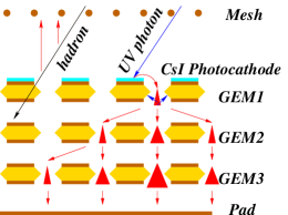
Three GEMs are used in the detector to provide the gas amplification of sasha . Without a focusing mirror the Cherenkov photons on the detector populate a circle not a ring thus the single electron detection does not improve the pattern recognition. In the HBD the signal is collected by hexagonal pads of a size slightly smaller than the size of the circle 333typical area of the pad in the final detector is 6.3 . This maximizes the signal collected on a single pad and provides extra rejection power to the hadrons. Ionization is always localized in one single pad while primary electrons producing Cherenkov light spread it over at least two adjacent pads.
The separation between a single electron and a close electron pair is done by the analyzing the amplitudes. According to the simulation the number of photoelectrons produced by a primary electron is 36. Such signal can be reliably distinguished from twice that number produced by a dilepton pair with a small opening angle.
3 Detector layout
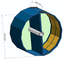
The HBD detector is shown in the right panel of fig. 2 it . The detector consists of two half-cylinder volumes made of honeycomb fiberglass sandwich panels. The top and bottom sectors, sitting outside the PHENIX fiducial acceptance are used for services and the six inner sectors are covered by a single piece Kapton film with 1152 pads printed on it. The film also serves as an additional gas seal. Particles enter the detector trough a 0.12 mm aluminized mylar window. 12 gas amplification modules as described above, are located on the inner side of each HBD vessel. Each module is 2723 cm2. GEMs used in them are subdivided into 28 HV modules to reduce energy stored in them in case of electric discharge. All GEMs in a module are powered with a single HV power supply through a resistive chain. The HBD will be operational in PHENIX in 2007 physics run.
References
- (1) A. Agakichev, et al, Phys. Rev. Letters 75, (1995) 1272; Phys. Letters B422, (1998) 405.
- (2) M. Floris et al, nucl-ex/0606023
- (3) A. Toia et al, nucl-ex/0510006
- (4) Z. Fraenkel, et al, www.phenix.bnl.gov/WWW/TPCHBD/WeizmannHBDProposal.ps
- (5) K. Adcox, et al, NIM A499, (2003) 469-479
- (6) Z. Fraenkel, et al, NIM A546, (2005) 466-480
- (7) Y. Giomataris and G. Charpak, NIM A310, (1991) 589-595
- (8) R. Pisani, et al, NIM A400, (1997) 243-254
- (9) F. Sauli, et al, NIM A386, (1997) 531-534
- (10) A. Kozlov, et al, NIM A523, (2004) 345
- (11) I. Tserruya, et al, NIM A563, (2006) 333