Performance of HPGe Detectors in High Magnetic Fields
Abstract
A new generation of high-resolution hypernuclear -spectroscopy experiments with high-purity germanium detectors (HPGe) are presently designed at the FINUDA spectrometer at DANE, the Frascati -factory, and at ANDA , the hadron spectrometer at the future FAIR facility. Both, the FINUDA and ANDA spectrometers are built around the target region covering a large solid angle. To maximise the detection efficiency the HPGe detectors have to be located near the target, and therefore they have to be operated in strong magnetic fields (T). The performance of HPGe detectors in such an environment has not been well investigated so far. In the present work VEGA and EUROBALL Cluster HPGe detectors were tested in the field provided by the ALADiN magnet at GSI. No significant degradation of the energy resolution was found, and a change in the rise time distribution of the pulses from preamplifiers was observed. A correlation between rise time and pulse height was observed and is used to correct the measured energy, recovering the energy resolution almost completely. Moreover, no problems in the electronics due to the magnetic field were observed.
keywords:
Hypernuclear -spectroscopy , HPGe detectorsPACS:
21.80.+a , 29.40.Wk , 29.30.Kv,
,
,
,
,
,
,
,
,
,
,
,
,
,
,
,
,
,
,
,
,
, and
††thanks: Part of doctoral thesis.
1 Introduction
High resolution -ray spectroscopy based on high-purity germanium (HPGe) detectors represents one of the most powerful experimental tools in nuclear physics. The introduction of this technique led to a significant progress in the knowledge of nuclear structure. It has been recently proven that also strangeness nuclear physics can benefit from the same advantages: the energy resolution of hypernuclear levels has been drastically improved from 1–2 MeV to a few keV in FWHM Tamura2000 ; Hashimoto2006 .
The success of such a technique has encouraged other groups working on FINUDA at DANE Bressani2005 and ANDA at FAIR PANDA ; joput to investigate whether this technique could be extended and incorporated in their set-ups. The FINUDA and ANDA magnetic spectrometers have a cylindrical geometry and are built around the target region covering a large solid angle (sr). To maximise the detection efficiency HPGe arrays are to be mounted near the target region, implying the operation of these detectors in a strong magnetic field (up to T). At DANE, collisions between electrons and positrons of 510 MeV lead to an abundant production of (1020) mesons, decaying predominantly into low energy ( MeV) K+K- pairs. The FINUDA spectrometer is centred around a set of eight thin (0.2 – 0.3 gcm2) nuclear targets, surrounding the interaction point. Since the year 2003 -hypernuclei produced by mesons stopped in these four targets have been studied Agnello2005 . At ANDA relatively low momentum can be produced in or reactions. A rather high luminosity is anticipated to be achieved due to retaining the antiprotons in a storage ring which will allow the use of thin targets. The associated will undergo scattering or (in most cases) annihilation inside the residual nucleus. Strangeness is conserved in the strong interaction and the annihilation products contain at least two anti-kaons that can be used as a tag for the reaction. In combination with an active secondary target, high resolution -ray spectroscopy of double hypernuclei and atoms will become feasible for the first time joput ; Hiyama .
The aim of the work described in this paper is to study the feasibility of using HPGe detectors in high magnetic fields and to study the associated effects on their energy resolution. The pulse shape distortion is also investigated.
2 Germanium Detectors in Magnetic Fields
Germanium detectors which are typically used in low energy nuclear spectroscopy (see e.g. jubeck1 ; jubeck2 ) are seldom operated in magnetic fields per and their behaviour under such conditions is not well known. Generally the deflection of the charge carriers in the magnetic field and the Penning effect in the vacuum surrounding the semiconductor can play a substantial role for the operation of large volume semiconductor devices in high magnetic fields.
For extended detector volumes and hence long drift paths the deflection of the charge carriers in the magnetic field may result in a larger rise-time of the signal due to longer drift paths or enhanced trapping and detrapping. By using standard shaping amplifiers the output signal reflects then the interplay between charge collection process and the transfer function of the amplifier. In practice an enhanced charge collection time will cause a reduction of the output signal even though the complete charge is collected eventually. In case of trapping the timescales involved may be significantly larger than the typical time constants of the electronic network and this reduction is referred to as a ballistic deficit Knoll . Sometimes this term is also used in a more general meaning bal1 ; bal2 for any decrease of the output signal due to an enhanced signal rise-time irrespective of its origin. In any case the associated larger fluctuations of the signal rise-time will deteriorate the energy resolution. Trapping of charge carriers and losses due to recombination depend on the type of the germanium. In the case of n-type germanium detectors which are studied in the present work trapping is expected to be less significant than in p-type germanium detectors. Nonetheless, a reduction of the signal may be particularly important in the case of major radiation damages of the crystal lattice (see e.g. rad ).
The bending force of the magnetic field causes charged particles produced within the volume between the Ge crystal and the capsule to spiral around the field lines. The longer travel times of the rest gas ions may result in an enhanced Penning effect. The interaction of electrons with the residual gas within the capsule may cause secondary ionisation leading eventually to discharges.
The generation of an electric field perpendicular to the magnetic field lines and the direction of the current (Hall effect) may affect small electronic components carrying large currents. While the wide spread use of silicon detectors and their associated readout electronics in tracking systems demonstrates the feasibility to operate highly integrated electronic devices in high magnetic fields (see e.g. simag1 ; simag2 ; simag3 ; simag4 ), the effect on the electronics of high resolution devices like HPGe detectors has not been studied yet.
3 Experimental Details
To verify that HPGe detectors can be safely and efficiently operated in a high magnetic field, two different kinds of detectors have been tested: the EUROBALL Cluster detector Eberth1996 and the VEGA detector Gerl1994 .
3.1 The EUROBALL Cluster Detector
The EUROBALL Cluster detector consists of seven large hexagonal, n-type, closely packed, tapered Ge crystals housed in a common cryostat Eberth1996 . The crystals have a length of 78 mm and a diameter of 70 mm at the cylindrical back-end. To protect the sensitive intrinsic surface of the detectors and to improve the reliability each crystal is encapsulated. The capsules are made of aluminium with a thickness of 0.7 mm. The distance of the Ge surface to the inner wall of the capsule is only 0.7 mm which gives a distance of mm between the edges of two neighbouring detectors in a cluster. Each capsule is hermetically sealed by electron beam welding of the capsule lid. The vacuum is maintained by a getter material which is active up to the temperature of 150o C. The cold part of the preamplifier is mounted on the capsule lid. The detector has a typical energy resolution of 2.1 keV (FWHM) at MeV for a 60Co source using an AC coupled preamplifier. The AC coupling was chosen in order to operate the detector capsule on ground potential which facilitates the close packing and the cooling of several detectors in a common cryostat. Since the seven crystals in the cluster are identical, only three crystals were taken as a representative for the measurements.
3.2 The segmented Clover Detector, VEGA
The super-segmented-clover detector VEGA Gerl1994 consists of four large coaxial n-type Ge crystals which are four-fold electrically segmented. The crystals have a length of 140 mm and a diameter of 70 mm. They are arranged in the configuration of a ”four-leaf” clover, and housed in a common cryostat. The core contact is AC coupled and the segments are DC coupled. The preamplifier used in the VEGA detector are similar to the one operated with the Cluster detector. Three crystals (B, C and D) and all four segments of one of the three (crystal B) were used in the present work. Prior to the studies in a magnetic field the energy resolution of the detectors was measured in the laboratory with a 60Co source to be about keV (FWHM) at MeV.
3.3 Experimental Set-up
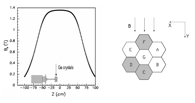
Two series of measurements were performed using the ALADiN dipole magnet ALADiN1988 . For both series the HPGe detectors and a 60Co -ray source, with an activity of 370 kBq, were positioned inside the magnet with the source placed in front of each detector. The ALADiN magnet aperture of m2 restricts to place a detector with its geometrical axis in the horizontal plane of the magnet. The direction of the magnetic field lines was perpendicular to the geometrical detector axis as shown in Fig. 1 (right). The magnetic field is maximal in the centre of the magnet and decreases along the -direction as illustrated in Fig. 1 (left). The detector end-caps have been placed as close as possible to the centre of the magnet in order to expose the germanium crystals to the highest magnetic field (about 7 cm from the centre as shown in Fig. 1).
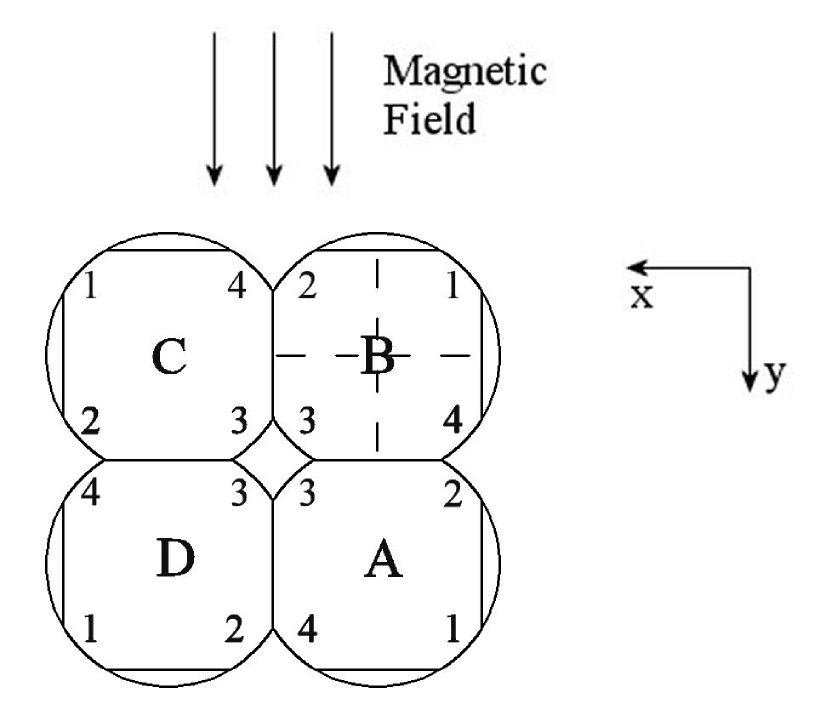
The 60Co source was placed at a distance of 27 cm and 20 cm away from the end-cap of the EUROBALL Cluster and VEGA detector, respectively. Fig. 1 shows the scheme of the crystals inside the Cluster detector in the right panel. For the measurements with the EUROBALL Cluster three channels (C, D, F) out of the seven Ge crystals of the Cluster were used. Channels C and D were fed with a voltage of 4000 V and channel F with 3500 V. For the measurements with the VEGA detector data from three (B, C, D) of the four Ge crystals were analysed. The geometry of the crystals of VEGA detector inside the magnet is shown in Fig. 2. They have been fed with voltages of 4000 V. The measurements can be divided in two groups: measurements done without magnetic field and those in which the magnetic field was tuned to 0.3 T, 0.6 T, 0.9 T, and 1.4 T for the EUROBALL Cluster detector and to 0.6 T, 1.1 T, 1.4 T, and 1.6 T for the VEGA detector. For each EUROBALL Cluster channel (C, D, and F) one of the preamplifier outputs was split in two signals. One signal was fed to a spectroscopy amplifier (Ortec 572) with 3 s shaping time, which output was digitised by an Analog-to-Digital converter (ADC Silena 4418/V, 8 channel, 12 bit resolution) and the second signal was fed to a VME 100 MHz Flash-ADC (FADC SIS3300, 8 channel, 12 bit resolution). The other output from the preamplifier was sent to a Timing-Filter-Amplifier (TFA Ortec 474), whose output was discriminated by a Constant-Fraction-Discriminator (Ortec CF 8000) to be used as a timing signal. The trigger was formed by a logic OR of the outputs from the three CFD channels. The ADC was read out via CAMAC bus.
Since the VEGA crystals are electrically segmented, the readout electronics differs from that corresponding to an EUROBALL Cluster in the trigger signal. One output of the preamplifier (core signal) for each channel was split in two branches as it was done for the EUROBALL Cluster set-up. Those preamplifier outputs corresponding to the the four segments of channel B were fed to the FADC. The trigger is formed from a coincidence of the logic OR of the CFD outputs of the four segments and an external trigger determined from the central core signal of channel B.
4 Data Analysis and Results
The analysis presented here is focused on the determination of the energy resolution from the pulse height spectra of both detectors by using conventional analogue electronics and on the study of the dependence of the pulse shape sampled by an FADC in magnetic fields. A detailed study on HPGe detectors operating with high rates in magnetic fields, based on the observation of pulse shapes, will be published in a forthcoming paper.
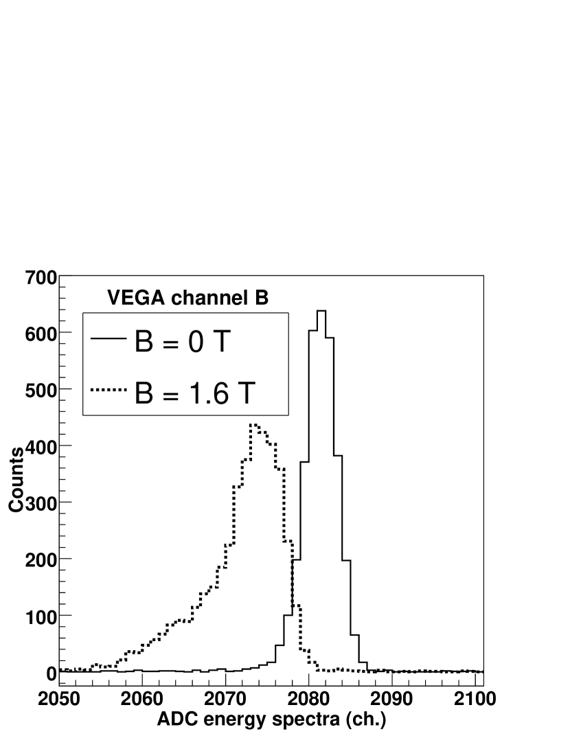
The energy resolution was extracted from the pulse height spectra by parameterising the 1.332 MeV -ray full-absorption peak from a 60Co source. From the parameterised line shape the value of Full-Width Half-Maximum (FWHM) was extracted. Two different methods were used to extract the energy resolution of the detectors depending on whether the spectra were measured in a magnetic field or not. Since in absence of a magnetic field the line shape of all detectors is very close to a single Gaussian distribution, the pulse height spectra have been parametrised by Gaussian function. In case the magnetic field was non-zero, the convolution of a Gaussian distribution and an exponential decay function was chosen to describe also the tail on the low-energy side of the peak. The observed line shape was fitted by a full absorption-peak superimposed on a quadratic background.
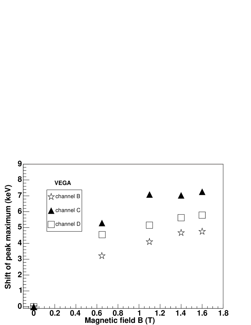
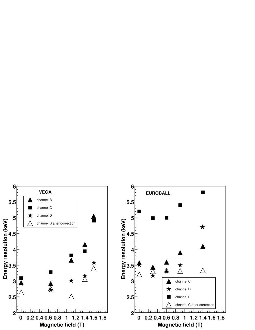
Pulse height spectra taken with a shaping amplifier are presented in Fig. 3 for the 1.332 MeV 60Co -ray line. Obviously, the line shape at T (dotted histogram) is significantly different from the line shape measured without field (solid histogram). The influence of the magnetic field causes a tail on the low-energy side. The dependence of the energy resolution (FWHM) on the strength of the magnetic field is shown for the EUROBALL Cluster as well as for the VEGA detector in Fig. 4. The energy resolution of one of the EUROBALL Cluster crystals is worse than the resolution of the two other crystals of the same detector because of pick-up noise in its electronic readout. In addition, the peak maximum of the -ray line shifts towards smaller energies with increasing field strength as shown in Fig. 5.
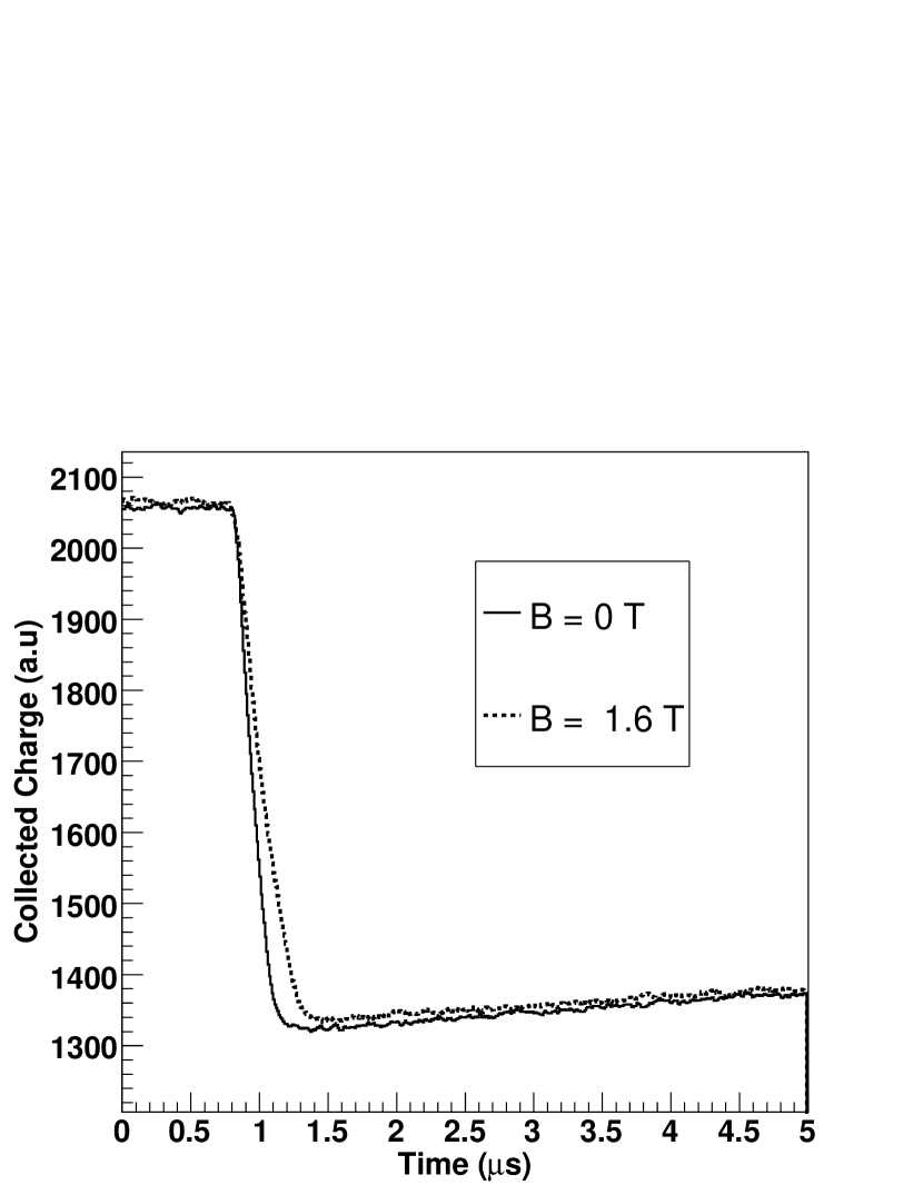
In order to clarify the question whether the shifts of the energy peak are due to a loss of charge carriers or whether this shift is caused by the interplay between an increased charge collection time in the Ge detector and the transfer function we have studied the FADC signals. Fig. 6 shows the averaged pulse shape signals for 1.332 MeV -rays measured at zero magnetic field (solid line) and at T (dashed line). The two signals have been obtained by averaging over 5000 events each. Within the two time intervals of [0, 0.5 s] and [3 s, 4 s] one finds mean amplitudes of 2056.7 (2065.7) and 1353.9 (1362.9) for T ( T), respectively. Despite a very different shape of the rising edge, the difference between the initial baseline and the signal level at later times stays nearly constant at a value of about 702.8 . This indicates that the recombination or long-time trapping of charges cannot account for the reduced energy signals presented in Fig. 5.
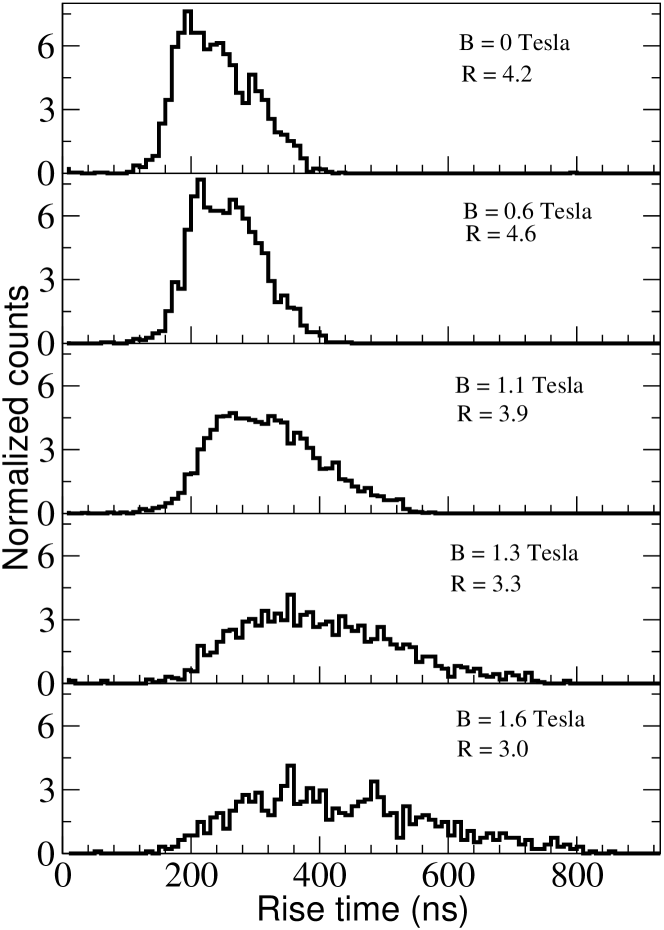
As can be seen already in Fig. 6, the pulse shape is modified by the magnetic field. Fig. 7 shows the distribution of the rise time (defined as the time it takes for the pulse to rise from 10 % to 90 % of its full amplitude) for different values of the magnetic field for the VEGA detector. A significant change of its mean value by approximately ns and a broadening of the distribution can be observed. The ratio between the mean rise time and the root mean square value decreases from values above at low magnetic fields to at T. This behavior is opposite to what is expected for a purely diffusive motion of the charge carriers. In the latter case an increase of R proportional to the square root of the rise time would have been expected.
The simultaneous large shift and the broadening of the rise time distributions on one hand, and the rather similar asymptotic values of the pulses seen in Fig. 6 on the other hand suggest that the incomplete signal integration by the main amplifier is the main origin of the observed energy shift. To verify the latter conjecture, the dependence of the amplifier transfer function on the variation of the rise time has been investigated with a pulse generator. This study confirmed that the rise-time variations are the main source of the energy shift seen in Fig. 5.
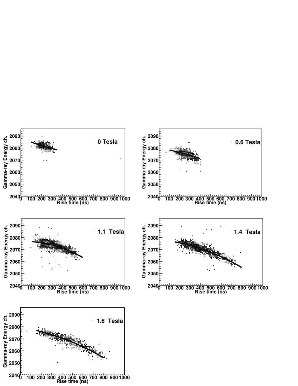
In order to explore the possibility to correct the shift of the pulse height by measuring the rise time event-by-event we show in Fig. 8 the correlation of the deduced -ray energy and the rise time for different magnetic fields. These distributions have been obtained event-by-event for the 1.332 MeV -line of one of the segments of VEGA channel B. For all magnetic fields the low-energy tail of the -ray peak (see Fig. 3) is associated with an increased rise time. The strong correlations observed in Fig. 8 provides a characterisation of the amplifier at different values of the rise time. The fit of a parabolic function to the correlation (see dark lines in Fig. 8) enables the correction of the energy spectra event-by-event for different magnetic fields. The correction functions are similar for all measurements at non-zero magnetic field, but they are shifted relative to that of the measurement at T. Presently the origin of this strong shift is not understood.
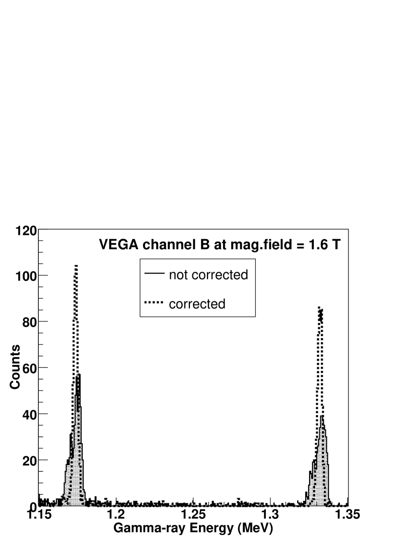
Fig. 9 shows the corrected -ray energy spectra (dashed line) for VEGA channel B at 1.6 T in comparison to the one without correction (hashed). A significant improvement in the peak shape has been obtained. After applying this correction of the pulse height spectra, an improvement on the energy resolution for VEGA channel B as well as for EUROBALL Cluster channel C has been achieved as shown in Fig. 4. The open triangles in Fig. 4 represent the energy resolution for both detectors after this correction.
5 Discussion and Conclusion
Two important effects have been observed by operating HPGe detectors in high magnetic fields: a small degradation of the energy resolution and a change of the pulse shape of the preamplifier signal.
All crystals of both detectors show a similar behaviour in the magnetic field with an energy resolution degradation of about 1–2 keV. However, the resolution is still sufficient to perform -ray spectroscopy on hypernuclei. The asymmetry of the line shape appears as a low-energy tail in the pulse height spectra in Fig. 3. Moreover, the mean value of the energy spectrum exhibits a shift to low energies as shown in Fig. 5. The measurements have been performed over a period of two days without observing any problems in the electronics or sparking effects. After the measurements the original energy resolution was recovered.
A significant shift and broadening of the rise times distribution has been observed in the presence of a high magnetic field. This observation reflects the effect of the magnetic field on the charge collection process itself.
The observation of a strong correlation between the measured pulse height measured with analogue electronics and the rise time measured by a FADC for various magnetic field strengths reveals the change in rise time as the major contribution to the degradation of the energy resolution. Employing this correlation for a rise time correction of the energy allows to almost recover the original energy resolution. The remaining degradation at fields larger than 1 T amounts to approximately 0.5 keV.
One could expect a dependence on the orientation of the detector with respect to the magnetic field. In our case a complete test of the orientation of the detector could not be carried out because of technical limitations Sanchez2004 : the aperture of the ALADiN magnet does not allow to freely rotate the axis of the detector. Nonetheless, the geometry of the setup used in the present study reflects the operating conditions of HPGe detectors in the future FINUDA experiment, since the detectors will be set up almost perpendicular to the direction of the magnetic field. On the other hand, the set-up of the HPGe detectors in the future ANDA experiment requires a further test with the magnetic field orientation almost parallel the detector axis.
The HPGe detectors were found to operate well in magnetic field conditions similar to those to be expected in future hypernuclear experiments at FINUDA and at ANDA . However, the detectors used in the present work are coupled to huge dewars for their cooling with liquid nitrogen. These dewars have been the main obstacle for the study of the dependence of the energy resolution on the orientation of the detector in the magnetic field of ALADiN. Furthermore they affect the detector integration in both the FINUDA and ANDA magnetic spectrometers. In order to circumvent these problems an electromechanical cooling system coupled to few encapsulated HPGe crystals is currently under development.
Acknowledgements
This research is part of the EU integrated infrastructure initiative Hadron Physics I3HP under contract number RII3-CT-2004-506078. We acknowledge financial support from the Bundesministerium für Bildung und Forschung (bmb+f) under contract number 06MZ176. T. R. Saito acknowledges the grant from the Helmholtz association as Helmholtz-University Young Investigators Group VH-NG-239. The authors are very grateful to the EUROBALL Owners Committee and the RISING collaboration for the availability of the Cluster capsules to study HPGe crystal behaviour in magnetic fields.
References
- [1] H. Tamura et al., Phys. Rev. Lett. 84 (26) (2000) 5963.
- [2] O. Hashimoto and H. Tamura, Prog. Part. Nucl. Phys. 57 (2006) 564.
- [3] T. Bressani, E. Botta, A. Feliciello, and V. Paticchio, Nucl. Phys. A754 (2005) 410c.
- [4] ANDA collaboration, Strong interaction studies with antiprotons, GSI report, GSI, Darmstadt, Technical Progress Report (Jan. 2005).
- [5] J. Pochodzalla, Nucl. Inst. & Meth. in Phys. Res B214 (2004) 149.
- [6] M. Agnello et al., (FINUDA collaboration), Phys. Lett. B622 (2005) 35.
- [7] E. Hiyama, M. Kamimura, T. Motoba, T. Yamada, and Y. Yamamoto, Phys. Rev. C 66(2002) 024007.
- [8] P. T. Greenlees et al., Eur. Phys. J. A20 (2004) 87.
- [9] A.-P. Lepp nen et al., Eur. Phys. J. A28 (2006) 301.
- [10] Chr. Bargholtz et al., Nucl. Inst. & Meth. in Phys. Res. A390 (1997) 160.
- [11] M. Descovich et al., Nucl. Inst. & Meth. in Phys. Res A545 (2005) 199.
- [12] G. F. Knoll, Radiation Detection and Measurement, John Wiley & Sons, Inc., New York, 1988.
- [13] B.W. Loo, F.S. Goulding and D. Gao, IEEE Trans. Nucl. Sci. NS-35 (1988) 114.
- [14] M. Moszyński and G. Duchêne, Nucl. Inst. & Meth. in Phys. Res. A308 (1991) 557.
- [15] P. G Rancoita, Nucl. Phys. 10 (1984) 299.
- [16] A. Castoldi, E. Gatti, V. Manzari and P. Rehak, Nucl. Inst. & Meth. in Phys. Res A399 (1997) 227.
- [17] F. Albiol et al., Nucl. Inst. & Meth. in Phys. Res A409 (1998) 236.
- [18] M. Brigida et al., Nucl. Inst. & Meth. in Phys. Res A564 (2006) 115.
- [19] J. Eberth et al., Nucl. Inst. & Meth. in Phys. Res. A369 (1996) 135.
- [20] J. Gerl et al., in: Proc. Conf. on Physics from Large -ray Detector Arrays, Berkeley, USA, LBL Report 35687, 1994, p. 159.
- [21] ALADiN Collaboration, Proposal for a forward spectrometer at the 4 detector, GSI Report 88-08, GSI, Darmstadt (1988).
- [22] A. Sanchez Lorente et al., in: GSI Sci. Report 2004, GSI, Darmstadt, 2005, p. 32, FAIR-EXP-23, and A. Sanchez Lorente et al., in: GSI Sci. Report 2005, GSI, Darmstadt, 2006, p. 79, FAIR-QCD-PANDA-07.