Dual Magnetic Separator for TRIP
Abstract
The TRIP facility, under construction at KVI, requires the production and separation of short-lived and rare isotopes. Direct reactions, fragmentation and fusion-evaporation reactions in normal and inverse kinematics are foreseen to produce nuclides of interest with a variety of heavy-ion beams from the superconducting cyclotron AGOR. For this purpose, we have designed, constructed and commissioned a versatile magnetic separator that allows efficient injection into an ion catcher, i.e., gas-filled stopper/cooler or thermal ionizer, from which a low energy radioactive beam will be extracted.
The separator performance was tested with the production and clean separation of 21Na ions, where a beam purity of 99.5% could be achieved. For fusion-evaporation products, some of the features of its operation as a gas-filled recoil separator were tested.
PACS: 07.55.-w; 07.55.+h; 29.30.-h; 41.85.-p; 41.75.-i; 25.70.Mn; 25.70.-z;
Keywords: Magnetic separator, Gas-filled separator, Secondary
radioactive isotopes
, , , , , , , , , , and
1 Introduction
Rare and short-lived radio isotopes are of interest because of their nuclear properties. They offer unique possibilities for investigating fundamental physical symmetries, for applied physics, and for nuclear structure studies [1]. The main motivation for investigating fundamental symmetries is to improve limits for the validity of the Standard Model, which can be inferred from high-precision measurements. Such low energy experiments are complementary to searches for new physics in High-Energy physics experiments. In particular, high accuracy can be achieved, when suitable radioactive isotopes can be cooled and stored in atom or ion traps [2, 3, 4, 5].
With this aim the TRIP (Trapped Radioactive Isotopes: icrolaboratories for fundamental Physics) facility at the Kernfysisch Versneller Instituut(KVI) in Groningen, The Netherlands, was proposed and funded in order to provide a state of the art user facility for such high-precision studies [6, 7]. While the magnetic separator of TRIP is the main topic of this article, we will briefly describe the complete facility consisting of several major subsystems in order to put the use of the separator into perspective.
A heavy-ion beam with a maximum magnetic rigidity of 3.6 Tm from the superconducting cyclotron AGOR [8] is used to produce a variety of short-lived isotopes using very different reaction mechanisms, such as fragmentation, charge-exchange reactions and fusion-evaporation. Primary beams ranging from protons to lead are available. In order to direct most of the reaction products into a relatively narrow forward-angle cone, the technique of inverse kinematics is used. This applies e.g. to charge-exchange reactions on a gaseous hydrogen target and fusion-evaporation on light-element solid targets. The maximum available beam energy is about 95 MeV/nucleon for fully stripped, lighter heavy ions (). The energy of heavy ions is restricted by the maximum charge state that can be reached with the ion source of the cyclotron. The heaviest ion accelerated with AGOR was 208Pb with an energy of 8.4 MeV/nucleon. In the various reactions, the beam and the reaction products travel together in a narrow cone in forward direction with the emittance of the products typically much larger than the beam emittance. The products and beam need to be separated efficiently, as will be described later.
At the exit of the separator, the produced isotopes have a considerable momentum corresponding to a maximum magnetic rigidity of about 3.0 Tm. Here, particles can already be stopped and measured in e.g. Si detectors to measure certain properties. For the program on fundamental physics a low-energy secondary beam must be produced. For this the particles will first be slowed in a degrader and stopped in a gas-filled ion catcher or a thermal ionizer. They will be extracted as singly charged ions and guided into a low pressure He-filled RFQ-Cooler buncher system and trapped in the last stage of the RFQ, which functions as a Paul trap. This will allow to produce a low energy bunched beam with a sufficiently small emittance and an energy of a few keV. This beam can be guided to one of several experimental setups. One of these is a Magneto-Optical Trap (MOT) assembly, where the actual measurements will take place.
The primary goal governing the design concept and the ion optics was to achieve an optimal separation of the wanted isotopes from other reaction products and the primary beam. Clearly two different types of reactions are foreseen. One involving the production of fast light isotopes from fragmentation or charge-exchange reactions, the other the production of slow heavy isotopes in fusion-evaporation reactions. The magnetic separator was designed to allow two modes, which we will refer to as the “Fragmentation Mode” and the “Gas-filled Mode” for the two types of reactions, respectively. In the first mode, fully stripped reaction products can be separated; in the second mode the charge-state distribution of partly stripped reaction products can be collapsed dynamically onto a single effective charge state with a suitable gas filling.
2 Design of the Dual Magnetic Separator
At the start of the design of the magnetic separator a list of criteria was established to develop a concept for the separator and to specify the design parameters.
-
1.
Production of a range of short-lived light (e.g. 21Na) to heavy radio isotopes (e.g. 213Ra), using heavy-ion beams from the AGOR cyclotron. The maximum energy is given by the operating diagram of the cyclotron and the maximum magnetic rigidity of 3.6 Tm of the beam line system. Beam stops should be designed for a maximum of 1 kW beam power dissipation.
-
2.
In the Fragmentation Mode an efficient collection of all desired reaction products in an achromatic focal plane, within a beam spot of the order of 2 cm total transverse dimensions.
-
3.
Effective separation of reaction products and beam, with a desired suppression factor .
-
4.
Rejection of undesired reaction products for a clean secondary beam, for experiments in the focal plane. (i.e. without the additional clean-up in the low energy section or in traps.)
-
5.
Optimal and cost efficient use of the existing infrastructure of the KVI experimental facilities.
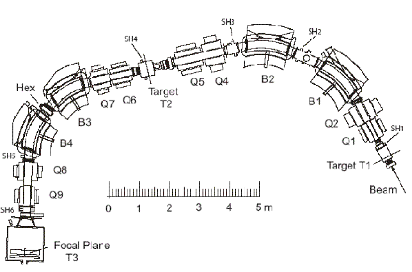
Based on these considerations the combined magnetic separator with the layout shown in Fig. 1 was designed. It is based on concepts used in previous magnetic fragment [9, 10, 11, 12, 13, 14, 15, 16, 17, 18] and gas-filled [19] separators. It is a special feature of the TRIP separator to combine both concepts in one single device so that it can operate in either the Fragmentation Mode or the Gas-filled Mode. The main design parameters are summarized in Table 1.
| Fragment Separator | Gas-filled Separator | |
| Beam rigidity B | 3.6 Tm (Beam line) | 3.6 Tm (Section 1) |
| Product rigidity B | 3.0 Tm (Section 1 and 2) | 3.0 Tm (Section 2) |
| Solid angle, vert., horiz. | 30 mrad | 30 mrad |
| Momentum acceptance | 2.0 % | 2.5 % |
| Resolving Power p/dp | 1000 | 2000 (no gas filling) |
| Momentum dispersion | 3.9 cm/ | 8.0 cm/ |
| Bending radius | 220 cm | 180 cm |
The complete magnet system consists of a total of four dipole (B1 – B4) and eight quadrupole magnets (Q1 – Q9). Q3 originally foreseen between B1 and B2 in the first designs could be omitted as discussed in section 3. There are three target chambers, the one referred to as “Target T1” is the target chamber used in Fragmentation Mode. The chamber “Target T2” is located at the intermediate focal plane in that mode. It serves as the target chamber in the Gas-filled Mode. The third chamber “Focal Plane T3” is positioned at the end of the separator. It is used for measurements in the focal plane. It can be replaced by the ion catcher. We will refer to the section between T1 and T2 as Section 1 and the section from T2 to T3 as Section 2. The provision of dipole doublets in each section instead of one larger single dipole has several advantages. The additional dipole edges allow for increased ion-optical control of quadrupole and higher order corrections. Access spaces are needed in the first section, between B1 and B2, for slits, scrapers and diagnostic systems and in Section 2 for a variable hexapole (HEX) for 2nd order corrections.
2.1 Fragment-Separator Mode
In Fragmentation Mode, Section 1 of the separator focuses the desired isotopes that are created in the object point (T1) in the intermediate focal plane (T2) with a momentum dispersion of 3.9 cm/. The dispersion created by dipoles B1 and B2 allows the separation of isotopes and beam with different rigidities. For this purpose slit systems SH2, 3, 4 were installed at the locations indicated, allowing to stop the beam at various positions depending on its momentum difference relative to the reaction products that enter Section 2. Access via additional ports to install shields and linings when the beam cannot be intercepted is also made possible. All spacers that define the gaps of the dipoles are protected from the direct beam by insulated spacers that allow current readout for monitoring purposes.
In Section 2 the dispersion is reversed. This provides a nearly achromatic image in the final focal plane so that all accepted ions of an isotopes are focused in the entrance aperture of an ion catcher at that location and the angular dispersion at T3 is nearly zero. Although this magnetic analysis only allows the separation of particles with different rigidities, this may be sufficiently selective when further purification of the beam follows in e.g. an optical trap. When the contribution of undesired particles is too high, or in the case of decay studies with stopped particles in the focal plane, additional purification is necessary.
To separate different nuclides with the same rigidity a simple and effective method [9, 10, 20, 21] is available that works well in our energy region. The energy loss of projectiles passing through a degrader depends on their atomic numbers Z and velocities v (E Z2/v2). This can be used to remove most of the ambiguities of the magnetic separation as the rigidities will differ after passing the degrader. We used a flat degrader at T2 to achieve further purification of the desired isotope and a slit system in the final focal plane. A degrader with constant thickness along the intermediate focal plane in T2, however, will perturb the achromaticity of the system. Therefore, when the accepted momentum range is large, a degrader in the form of a “wedge” can be used to maintain achromaticity. This may be done by bending the foil along an appropriate curve.
2.2 Gas-filled Separator Mode
The separation concept of the Fragmentation Mode described above does not work for heavy particles at low energies. Here ions emerge from the production target with a wide charge-state distribution. The magnetic rigidity B, being proportional to the momentum and inversely proportional to the atomic charge is not a good measure of the momentum anymore. In particular, the charge distribution of the beam can cause serious problems. Even if a charge-state fraction is relatively small, the number of beam particles can still be orders of magnitude larger than the desired reaction product at its optimal rigidity.
A method to solve this problem may be the use of finger beam stops in the dispersive plane. This was done in the HRIBF Recoil Mass Separator [15] to prevent high intensity beam components from arriving at the final focal plane.
A method that improves both the separation and increases the transmission is the Gas-filled Mode [19]. Ions passing through such a system will undergo frequent charge-changing atomic collisions with the net effect of an average charge qaver and therefore an average magnetic rigidity. This can improve the transmission of ions through a magnet system at the expense of a certain but often acceptable increase of the emittance of the ion beam due to multiple scattering. This method is particularly useful in fusion reactions where the evaporation residues have a well defined velocity. Typically one uses normal kinematics in these reactions to guarantee complete separation when the fusion cross sections are extremely small. For secondary beam production, however, when clean separation is not essential and an ion catcher with large acceptance can be employed, also inverse kinematics can be used. We will come back to this discussion in section 8. In the dual magnetic separator this mode can be realized by operating Section 2 in Gas-filled Mode. The target is then located at T2.
3 Ion optics
Extensive first order ion-optical studies were conducted to design a separator magnet system that could accommodate both Fragment and Gas-filled Modes. This led to the specifications summarized in Table 1. While the system is mainly designed to accommodate the desired reaction products, also the ion optics of the separated beam had to be considered for a variety of circumstances to allow a clean separation and elimination of a high-intensity primary beam. Constraints of fixed building and shielding structures require that the separator has to be very compact without giving up flexibility for the different operational modes and production reactions.
Special effort was made to minimize the number of quadrupoles. An initially considered quadrupole (Q3) between dipoles B1 and B2 could be omitted. This was possible by adjusting the edge angles of B1 and B2. It is, however, not possible to eliminate any of the present eight quadrupoles without compromising one or the other design requirement of the facility. As an example, in the Fragmentation Mode quadrupole Q4 might be omitted at the cost of flexibility; however, it is absolutely necessary in the Gas-filled Mode where Section 1 is used as beam line. This also requires reversing the polarity of quadrupole Q4 and Q5 to obtain a small beam spot at T2.
First-order design calculations of the beam and initial calculations of the separator were performed using the TRANSPORT code [22]. The quadrupole gradients provided by the dipole edge angles, seen in Fig. 1 were adjusted to reduce not only the number of quadrupoles as mentioned above, but also to minimize the quadrupole magnet strengths. This was crucial for minimizing the size and power consumption of the large quadrupoles.
Due to the large angle and momentum acceptances, higher order calculations were indispensable and were conducted using the COSY Infinity code [23]. Aberrations up to 3rd order were found that would have significantly affected the design parameters. They were reduced by shaping the edge curves of the eight available dipole ends as can be seen in Fig. 1. In addition a hexapole (HEX) was included between dipoles B3 and B4. This hexapole improves the optics by reducing 2nd order aberrations in the Fragmentation Mode.
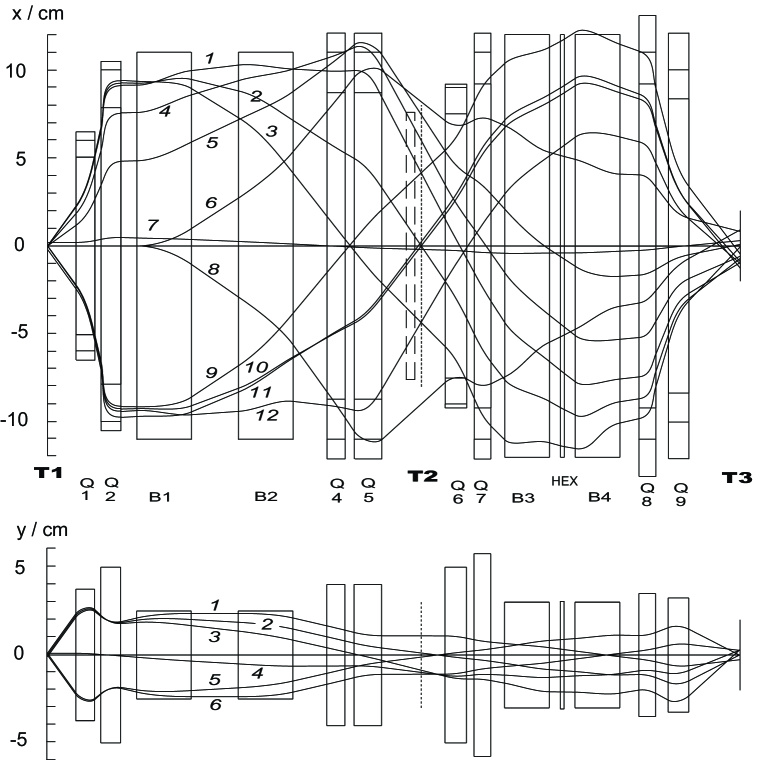
Results of the final ion-optical design calculations in 3rd order of the Fragmentation Mode in horizontal (x) and vertical directions (y) along the central ray (z) are shown in Fig. 2. The system is 9.82 m long from the target location T1 to the dispersive plane T2 (indicated by the dotted line) and 18.20 m to the achromatic plane T3. The effective field lengths (EFL) and good field regions of the four dipole magnets B1 - B4 are indicated by the rectangles. For the quadrupoles Q1 - Q9 the rectangles indicate in z direction the EFL, while the transverse boundaries given by the three lines indicate the dimensions, starting from the inside, of the pole radius, the good field region, and the physical limits of the vacuum chambers, respectively. The dashed box in front of T2 indicates a temporary horizontal limitation, which will be removed later. To elucidate the optics, twelve horizontal and six vertical rays characteristic for the separator operation are shown in Fig. 2, the starting values of the rays are listed in Table 2.
| ray | x [mm] | [mrad] | E/E [%] | y [mm] | [mrad] |
|---|---|---|---|---|---|
| 1 | 0 | 30 | 2.2 | -1 | 30 |
| 2 | 0 | 30 | 0 | 0 | 30 |
| 3 | 0 | 30 | -2.2 | 1 | 30 |
| 4 | 0 | 25 | 3.2 | 1 | 0 |
| 5 | 0 | 16 | 4.0 | 0 | -30 |
| 6 | 0 | 0 | 4.4 | 1 | -30 |
| 7 | 2 | 0 | 0 | ||
| 8 | 0 | 0 | -4.4 | ||
| 9 | 0 | -30 | 2.2 | ||
| 10 | 0 | -30 | 0 | ||
| 11 | -2 | -30 | 0 | ||
| 12 | 0 | -30 | -2.2 |
The three pairs of horizontal rays (1/9),(2/10), and (3/12) show the dispersive focal plane in T2 with an energy dispersion of 1.95 cm/. The rays 7 and 11 explore the effects of a target size of 2 mm. The rays 1, 4, 5, 6, 8 and 12 test the energy acceptance as function of angle. At 0∘, particles with an energy spread of 4.4 will be accepted limited by the good field region of quadrupole Q5. The accepted energy spread will gradually decline with increasing angle. At the maximum accepted angle of 30 mrad the maximum accepted energy spread is 2.2%.
All horizontal rays arrive at the focal plane T3 within a space of 20 mm, sufficiently small for the following degrader/ion catcher. This was achieved by 2nd order corrections built into the dipole entrances and exits and the hexapole HEX. This hexapole has an effective field length of 150 mm and an aperture radius of 90 mm with a maximum pole tip field of 0.07 T. The horizontal image size is minimized by an appropriate hexapole excitation. It will increases to about 30 mm if the hexapole magnet is switched off. The vertical ion optics is designed to keep all rays within the gaps of 50 mm of the dipoles B1 and B2 and 60 mm of B3 and B4. The focal plane angle at T2 is close to 90∘. The vertical envelop at T2 is relatively large due to the vertical magnification of -10.0 but a small vertical image of about 5 mm is achieved in the final focal plane T3 mainly due to the magnification of 3.4 at this location. The horizontal magnifications for Section 1 and the complete system are -0.95 and 1.8, respectively. The above calculations show that for full transmission, target spot sizes of less than 2 mm horizontally and 1 mm vertically are required.
| ray | x [mm] | [mrad] | E/E [%] | y [mm] | [mrad] |
|---|---|---|---|---|---|
| 1 | 0 | 30 | 4.0 | -1.5 | 30 |
| 2 | 2 | 30 | 0 | 0 | 30 |
| 3 | 0 | 30 | 0 | 1.5 | 0 |
| 4 | 0 | 0 | 4.0 | 0 | -30 |
| 5 | 0 | 30 | -4.0 | 1.5 | -30 |
| 6 | 2 | 0 | 0 | ||
| 7 | 0 | -30 | 4.0 | ||
| 8 | 0 | -30 | 0 | ||
| 9 | 0 | -30 | -4.0 |
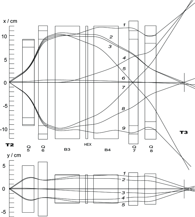
In the Gas-filled Mode, Section 1 serves as beam line and the target (e.g. a carbon foil) is installed at T2. A thin window (e.g. 2.5 m HAVAR) is installed in front of the target to separate the evacuated beam line and the gas-filled section. The ion-optical design is shown in Fig. 3. This is the initial magnet setting without gas filling. The ion optics will be changed significantly when the system is gradually filled with gas for optimum separation of beam and products since the particles gradually decrease in energy along their path from T2 to T3.
The upper panel shows the magnetic elements and nine selected rays in the horizontal midplane. The lower panel shows five vertical rays. The starting values of the test rays are listed in Table 3.
The three pairs of horizontal rays (1/7),(3/8), and (5/9) show the dispersive focal plane in T3 with an energy dispersion of 4.0 cm/. The rays 2 and 6 explore the effects of a target size of 2 mm. Ray 4 shows a trace at 0∘ with an energy difference of %. All horizontal rays of a certain momentum arrive at the focal plane T3 within 10 mm. This was achieved by 2nd order corrections built into the dipole entrances and exits as mentioned above. The vertical ion optics is designed to keep all rays within the gaps of 60 mm of the dipoles B3 and B4. The above calculations show that for full transmission, target-spot sizes of 2 mm horizontally and 1.5 mm vertically or smaller are required. The focal plane angle at T3 is 70∘ due to the concave curvatures of the effective field boundaries of B4. This correction is not optimal for the Fragmentation Mode, but the hexapole between B3 and B4 can be used to minimize the beam-spot size at T3. As we will see below the image size in this mode is dominated by statistical charge-changing processes in the gas.
4 Magnet Design
The magnets are designed to provide the good field region required in both transverse directions and the necessary field strength according to the ion-optical calculations. All magnets are operated by highly stabilized direct currents and are designed to operate at fields below 1.65 Tm where iron saturation could be kept small. All iron pole pieces and return yokes are therefore machined of solid, soft iron. All coils are normal conducting with hollow copper conductors to allow water cooling. The coil temperatures are kept below 55∘ C. All magnets including their vacuum chambers and supports were manufactured by commercial vendors with significant experience in the design and construction of similar magnet systems.
4.1 Dipole Magnets
The four dipole magnets were manufactured by the Danfysik company according to the specifications summarized in Table 4. All dipole magnets are H-type magnets. In order to achieve the good field region for a minimum of magnet iron, two special features are incorporated in the design:
-
(i)
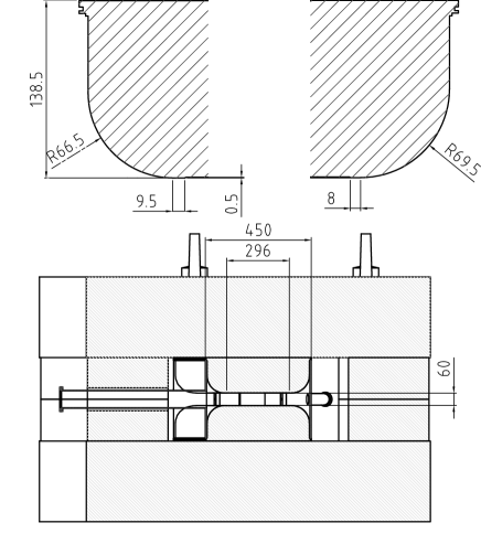
The radial profile has circular side profiles with modified Rose shims as shown by the measures in the upper part of Fig. 4. This allows for dipole B1 and B2 with a gap of 50 mm, a horizontal good field region of 220 mm with a pole width of only 400 mm. Dipole B3 and B4 with gaps of 60 mm have the same characteristics with a slightly larger good field region of 240 mm, as required, and a pole width of 450 mm. This pole face shaping saves some 30% of the iron compared to magnets with traditional Rose shims and homogeneous regions of the same size.
-
(ii)
The amount of magnet iron is further reduced by a wrap-around chamber which is precision machined and subsequently welded to the sides of the pole piece with special, thin welding lips to minimize heat effects in the magnet iron. The accuracy of the gap is maintained by precision, non-magnetic spacers that are held with bolts through the pole pieces. All spacers are protected from excessive beam and heat exposure by insulated tungsten shields that allow to monitor any beam current hitting the shields.
| Parameter | Dipole Magnet Type | ||||
| B1 | B2 | B3 | B4 | ||
| Bending radius | mm | 2200 | 2200 | 1800 | 1800 |
| Max. rigidity | Tm | 3.6 | 3.6 | 3.0 | 3.0 |
| Max. magnetic field B | T | 1.64 | 1.64 | 1.67 | 1.67 |
| Bending angle | deg | 37.5 | 37.5 | 37.5 | 37.5 |
| Central ray arc length | mm | 1439.9 | 1439.9 | 1178.1 | 1178.1 |
| Vertical gap, full size | mm | 50 | 50 | 60 | 60 |
| Good field region, dB/B 0.02 | mm | 220 | 220 | 240 | 240 |
| Pole width | mm | 400 | 400 | 450 | 450 |
| Entrance edge angle, vert. focusing | deg | 18.75 | 10.0 | 0 | 0 |
| Entrance edge curvature, 1/radius | 1/m | 0.67 | -0.2 | 0.88 | -0.2 |
| Exit edge angle, vert. focusing | deg | 10.0 | 18.75 | 18.75 | 18.75 |
| Exit edge curvature, 1/radius | 1/m | 0.0 | -1.29 | 0.0 | -1.36 |
| Max. current for magnet | A | 380 | 380 | 380 | 380 |
| Max. Voltage for magnet | V | 90 | 90 | 80 | 80 |
| Weight of iron | kg | 11000 | 11000 | 11000 | 11000 |
| Weight of coil | kg | 600 | 600 | 500 | 500 |
As shown in Fig. 1, all magnets have 0∘ ports in both directions for viewing, alignment and other access needs that may arise. Additional ports are provided in the middle of the magnets through the inside return yoke. These ports were used for radial field maps with Hall probes and to obtain the magnetic flux B versus current, B(I), with NMR probes immediately after assembly. Hall probes will be installed permanently to allow setting of the fields without having to consider hysteresis and saturation that affect settings according to coil currents.
The dipole design specifications in Table 4 include maximum current and voltage requirements to allow the use of power supplies for the dipole magnets from other KVI facilities that cannot run when the beam is used in the TRIP facility. For this reason dipole magnets B1 and B2 are powered in series by one power supply. Small correction coils are mounted on top of the main coils allowing for tuning differences between both dipoles up to 3. The dipoles B3 and B4 are powered independently by using existing power supplies.
While 3-dimensional field calculations were performed by the manufacturer to predict the end packs for the proper edge angles and hexapole components, it was decided to machine the magnet ends so that additional shims would allow small corrections. For this purpose, the dipole magnets were assembled at first without welding the vacuum chambers onto the pole pieces for access reasons. The radial and B(I) field maps through the middle port were performed as mentioned above. Subsequently field maps in the midplane with a grid distance of 10 mm were performed in the fringe field regions and in the middle of the magnets within a section of 7∘ of the bend angle. In the measured homogeneous part we verified that the field did not deviate more than from the average field. The effective field boundary shapes were verified up to 2nd order and for the entrance of B1 and B3 up to 3rd order. We required a deviation less than 0.3 mm from the design shape without field clamps. By adding shims on the end packs on either side of the central ray, corrections between 0 mm and 2 mm brought the magnet fields within specification with the exception of B4 where the deviations exceeded slightly the 0.3 mm requirement. Higher order COSY calculations were used to verify that the remaining deviations did not jeopardize the resolving power design specifications given in Table 1. Some of the eight end packs did not need corrections, a few needed one iteration, and only in two cases a second iteration was necessary. Final field maps for all dipole magnets were performed, documented and are available for future purposes.
After a dipole magnet was optimized with this procedure, it was disassembled and the vacuum chamber welded in place. In order to verify that this welding and reassembly procedure did not affect the original field map, we mapped one magnet again, obviously with a somewhat reduced mapping region with the vacuum chamber in place. The result showed an identical field map within the accuracy of the measuring method and well within specifications. A small but measurable deviation was found in the fringe field region where the rather thick exit port is welded in place. This deviation was within specifications.
4.2 Quadrupole Magnets
| Parameter | Quadrupole Magnet Type | ||||||||
|---|---|---|---|---|---|---|---|---|---|
| Q1 | Q2 | Q4 | Q5 | Q6 | Q7 | Q8 | Q9 | ||
| Overall length | mm | 580 | 680 | 630 | 880 | 680 | 680 | 700 | 700 |
| Focusing strength | T | 8.2 | 6.2 | 5.0 | 6.3 | 5.6 | 2.8 | 2.0 | 3.3 |
| Eff. field length | mm | 480 | 550 | 500 | 780 | 550 | 420 | 420 | 500 |
| Gradient | T/m | 17.0 | 11.3 | 10.0 | 8.1 | 10.2 | 6.7 | 4.8 | 6.7 |
| Horiz. good field | mm | 120 | 200 | 220 | 220 | 180 | 220 | 220 | 200 |
| Aperture diameter | mm | 100 | 167 | 184 | 184 | 150 | 184 | 184 | 167 |
| Max.pole tip strength | T | 0.85 | 0.95 | 0.88 | 0.75 | 0.77 | 0.62 | 0.45 | 0.56 |
| Current, magnet | A | 256 | 380 | 398 | 460 | 360 | 255 | 160 | 255 |
| Voltage, magnet | V | 37 | 107 | 74 | 62 | 102 | 78 | 36 | 78 |
| Power supply rating | A | 270 | 400 | 420 | 480 | 380 | 270 | 180 | 280 |
| V | 45 | 115 | 80 | 70 | 110 | 90 | 45 | 90 | |
| Magnet weight | kg | 800 | 3180 | 1550 | 4900 | 3180 | 1650 | 630 | 1650 |
| Inhomogeneity | 0.2% | 0.2% | 0.2% | 0.2% | 0.2% | 0.2% | 0.2% | 0.2% | |
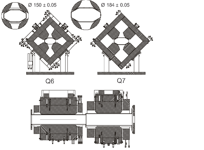
There are eight quadrupoles in the separator system, manufactured by the company SigmaPhi according to the specifications in Table 5. The horizontal good field regions are required to be significantly wider than the vertical ones, reflected in the shape of the vacuum chambers. As an example this is shown in Fig. 5 for the quadrupole doublet Q6, Q7. All quadrupole magnets were mapped and tested at the factory and delivered including the vacuum chambers and supports. As in the case of the dipole magnets, most of the electrical specifications were determined to allow the use of existing power supplies except for two power supplies that had to be purchased.
5 Diagnostics and Instrumentation
For the proper setup, optimization and operation of the separator a series of diagnostic elements is needed. A variety of devices are required to tune and stop the beam, in addition standard Si solid state detectors were used in the intermediate and focal plane to observe the fragments. Some of the instrumentation is discussed below.
5.1 Beam diagnostics and stops
The target chambers T1 or T2 and the vacuum chamber between B1 and B2 are equipped with retractable harps. The harps consist of 24 wires that are stretched in horizontal and vertical directions with 1 mm or 2 mm spacing. Signals from the wires are individually read out and visualized as a beam profile in vertical and horizontal directions. The harps are standard equipment for beam tuning in the beam lines [24]. They can be operated to tune with the full beam and viewed simultaneously in the setup phase of an experiment. In T1 and T2 target ladders are used with scintillating targets, they can be viewed by means of CCD cameras through plexiglass ports. The lifetime of these viewing targets (Zn2SiO4 on Al foil) is limited. They are mostly used for the final tuning. Both snapshots of the harp data and viewing targets can be stored for reference. In the commissioning phase scintillating screens were also used on a movable platform in a focal-plane chamber T3.
In anticipation of high beam currents, the beam stops in front of T1 and T2 have been designed to allow water cooling. When tuning for fragments the beam is stopped on one of the slits located at SH2, SH3, or SH4 for the Fragmentation Mode and SH5 or SH6 for the Gas-filled Mode.
At present there are three pairs of horizontally movable slits that are remotely controlled and can be installed at any of the mentioned locations depending on the requirements of the experiment. The movable slits are also used to verify the ion optics, e.g. focus conditions in conjunction with the beam or other setup conditions.
5.2 Particle identification
In order to optimize the separator for transport and focusing of the desired reaction products at the exit of the separator, it is important to have online particle identification. While the optimal detection system depends on particle type, we have used a 100 m thick Si detector with a diameter of 20 mm that provided either energy E or energy loss E and a timing signal. As we will see below, this detection is well suited for identifying light to medium-mass particles. One detector is permanently mounted on a movable arm (horizontal plane) in T2. During the initial tests and development runs, a second Si detector was mounted on a movable table at the focal plane T3.
5.3 Gas target
The Fragmentation Mode has been tested with the 1H(21Ne, 21Na)n reaction. For initial tests with low beam intensities, thin polyethylene foils as hydrogen targets were used, with carbon as the only other target component. The hydrogen content of these targets, however, will diminish rapidly with higher ionization density, i.e. when the beam current is increased or for low energy and/or heavy element beams.
For higher beam currents, a hydrogen-filled gas target is used. This target has 2.5 m HAVAR foils as windows following a design of a target in use at Texas A&M [25]. In order to increase the density by about a factor of 4, the gas cell is cooled down to liquid nitrogen temperature. The gas cell is approximately 10 cm long with windows of 1.25 cm diameter. It can be moved vertically to allow insertion of a target ladder at the object position in T1. The gas target and its accessories were designed and produced at North Carolina State University [26].
5.4 Separation by differential stopping
In Fragmentation Mode, the separator Section 1 provides a dispersive focal plane, where the beam - if not stopped previously - and other undesirable products can be separated by momentum selection using horizontal slits. The design momentum acceptance of 2 translates in a 16 cm wide focal plane due to the momentum dispersion of about 4 cm/. Magnet Section 2 reverses the effect of the dispersive function of Section 1 and provides an achromatic beam spot of the order of 20 mm diameter, well suited to be accepted in a following ion catcher.
However, all particles, including the undesirable ones, that pass through the momentum slits will also enter the ion catcher. For further separation a degrader can be used. Such a degrader will provide mass selection, because of the differences in energy loss. Because of the momentum acceptance of 2 also the desired products will be dispersed, effectively disturbing the achromaticity. This effect can be eliminated by changing the thickness of the degrader along the dispersive plane. Such a degrader is called a ”wedge” and can be realized by bending a foil of constant thickness. A holder for bent foils with dimensions corresponding to the intermediate plane was made.
6 Installation and commissioning
In November 2003 the modifications of shielding and the installation of power and utility lines in the designated TRIP separator hall (T-cell) was completed. At this time all major components, in particular the magnets and their support, had been delivered. Only two additional power supplies had to be purchased as most of the magnets were designed to be able to use existing power supplies not operated at the same time as the TRIP separator.
Installation of the separator itself started in December 2003 and was completed in April 2004 followed by commissioning runs in May 2004. We tested the basic ion-optical parameters using a 43 MeV/nucleon 21Ne7+ beam (B = 2.86 Tm). A nearly circular primary beam spot of about 2 mm diameter (FWHM) was achieved at T1. This beam was transmitted into the dispersive focal plane at T2 where it had dimensions of 5 mm by 8 mm in the horizontal and vertical directions. The beam was subsequently put onto a viewer at T3, where the achromatic image size was approximately 10 mm by 10 mm in both transverse directions. In order to verify the momentum dispersion and to obtain information about the momentum acceptance, copper foils of 7.5, 15, and 22.5 m were inserted at the target location T1. The displacement at T2 was measured using a large Zn2SiO4 viewer marked with a centimeter scale. The momentum loss of the beam in a 22.5 m foil was 1.0. The beam consists of fully stripped 21Ne10+ ions after the target. The momentum dispersion measured in the dispersive focal plane (T2) was 4.2 cm/ corresponding to 2.1 cm/ energy dispersion in non-relativistic approximation. This is in agreement with the design calculations. A circular beam spot of about 20 mm diameter (FWHM) was observed in the achromatic final focal plane (T3).
The ion optics of the Gas-filled Mode was tested by transporting the 21Ne7+ beam onto the target T2. Without gas filling the momentum dispersion in the final focal plane was measured by inserting the copper foils and using the method mentioned above. The resulting momentum dispersion of 6.9 cm/ is in agreement with the design calculations. After having verified the basic optical design parameter and that all separator components worked satisfactorily, we proceeded to produce 21Na isotopes required for one of the initial experiments.
7 Production of 21Na in Fragmentation Mode
After successful commissioning and verification of ion optics and design parameters, we produced 21Na using the (p,n) reaction in inverse kinematics with a 21Ne7+ beam at 43 MeV/nucleon. A 20 mg/cm2 polyethylene (CH2)n foil was used in setup runs where low beam intensity of a few nA current was sufficient. For higher beam intensities of up to 30 particle nA we used the LN2 cooled hydrogen target at 1 atm. The emerging 21Ne10+beam with a magnetic rigidity B approximately 9 higher than the desired 21Na11+ isotopes is stopped in the movable beam stop SH2 between the first dipole magnets B1 and B2. The movable arm with the 100 m thick, circular silicon detector of 20 mm diameter is installed immediately downstream of the wedge in chamber T2. A second silicon detector of 150 m thickness was installed in the focal plane T3 also on a platform that moves along the horizontal axis.

The left side panel of Fig. 6 shows the energy loss of particles in the detector at T2 vs. the time-of-flight (TOF) relative to the Radio-Frequency (RF) phase of the cyclotron. The RF was 32 MHz, providing a dynamic range of 31 ns for the TOF measurement, just sufficient to observe the dynamic range of particles in the Ne mass region without “wrap-around” that would complicate particle identification. Due to the nature of the reaction the 21Na products are strongly focused and most of these fragments pass through the detector, i.e. the setting of the magnetic fields in Section 1 is adjusted to optimize the 21Na yield. The detector is left in place during the measurements at T3, functioning as a uniform degrader. In the panel on the right hand side the same spectrum is shown but this time with a gate on particles arriving in the detector at the focal plane T3 that has also a 20 mm diameter. Optimizing the rigidity of Section 2, one can tune for the maximum yield of 21Na. Only a small contribution of 0.5% of 20Ne is remaining while all other impurities including beam particles are reduced to insignificant contributions. Note that in this test run the left side spectrum was measured using a polyethylene foil, while the right side was measured with the cooled hydrogen target to allow higher beam and therefore higher production rates. 21Na/particle-nA /s of primary beam was already achieved. In these and other production measurements we profited greatly from using the code LISE++ of Tarasov and Bazin [11, 12] which allows to enter the specification of the separator. Unfortunately, it does not yet work for direct reactions, so that the fragmentation or fusion-evaporation mode of the program has to be used for initial settings of the separator. Recently we produced 22Mg, 20Na, 19Ne and 12N. All using inverse (p,n) reactions except for 22Mg where a 23Na beam was used in a (p,2n) reaction at 32 MeV/nucleon. Production of 20Na and 19Ne was optimized resulting in a yield of and /s/particle-nA, respectively.
For 1 kW beam the 21Ne mentioned above corresponds to 1.1 particle-A. The maximum useful target thickness is obtained when the energy loss difference of the primary beam and the secondary beam corresponds to the energy acceptance (8 %) of the separator. Note, that using a H2 target the pressure windows only affect the acceptance due to straggling but not due to energy loss. In this way using a 10 bar target one may reach 108 21Na particles/s.
This clean secondary 21Na beam was used later in a first experiment in collaboration with a group from LPC, Caen, France [27] to study the -decay branching ratio in the 21Na decay. This ratio is important for the interpretation of the - correlation measurements [28] performed as tests of the Standard Model.
8 Tests of Gas-filled Mode
The planned physics program [5, 6] requires also the production of very heavy isotopes like 213Ra that may be produced by using the fusion-evaporation reaction in inverse kinematics. If the radium atom has nearly degenerate states of opposite parity, 213Ra could be a candidate for the search for a (forbidden) permanent electric dipole moment.
In an early phase of the design, calculations were made with the transport code from M. Paul [19], which incorporates charge-changing atomic collisions and energy loss in a gas-filled magnetic system. In particular the reaction 206Pb on 12C was considered where one could collect all Ra residues with 100% efficiency, as the effect of the evaporated neutrons is negligible compared to broadening due to multiple scattering in the gas. The simulations were made to find whether the residues and the beam can be separated sufficiently. In this application a clean separation is not essential if the ion-catcher device can handle the additional load due to the beam contamination. In Fig. 7 the result of this calculation is shown for a Pb beam of 7 MeV/nucleon on a carbon target placed at T2 with Section 2 filled with 5 mbar Ar. Note that the separation increases with increasing pressure due to the difference in stopping power. The separation is about 13, where is the Gaussian width of the position distribution of Pb; the separation expressed this way is not sensitive to the pressure. The Gaussian width found in the simulation shown in Fig. 7 is 2.5 cm, i.e., nearly 6 cm Full Width at Half Maximum (FWHM).
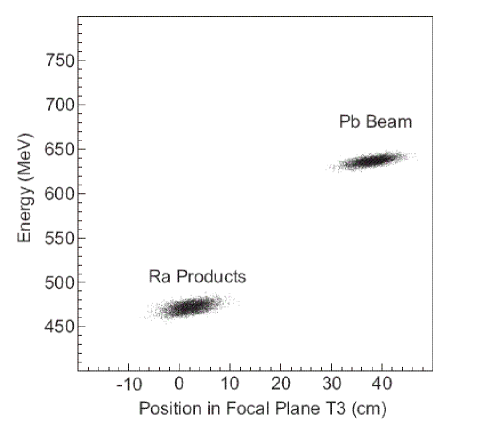
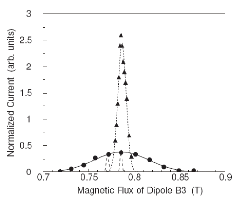
To test some of the results a measurement was made with a 206Pb29+ beam of 8.4 MeV/nucleon passing through a HAVAR window of 2.5 m thickness before impinging on a carbon target of 4.2 mg/cm2 thickness. Results are shown in Fig. 8. Without gas filling the charge distribution after passing the foil and the target is given by the full circles. A total of eleven charge states with a maximum intensity estimated to be at q=60 were observed. The line through the points is a Gaussian distribution with a FWHM of 9% p/p. A more detailed measurement over two charge states is indicated by the two dashed Gaussian curves that have each a FWHM of 0.37% p/p. This is the overall resolution of the beam, including straggling in the entrance foil in front of the target. The triangles represent a scan over the focal plane after filling the complete system after the entrance foil with 2.5 mbar Argon gas. The eleven separated charge states are now concentrated in a single peak corresponding to an average charge state due to the statistical process of charge-state changes in the gas. For comparison of the data sets the measured setting of the data obtained with gas filling were shifted in momentum to coincide with the maximum of the charge distribution measured in vacuum. For the same reason the beam current data were scaled to obtain the same total integrated particle current. The resulting distribution is well reproduced by a Gaussian distribution, as can be observed from the fitted dotted curve. The FWHM was 1.4% p/p or 8.6 cm in absolute width, i.e. nearly 4 times the width of a single charge state, but 6 times smaller than the full charge distribution. Also the dependence on Ar gas pressure was investigated. Since the ion optics changes due to the energy losses in the gas, after each pressure change the magnet settings had to be adjusted empirically for best resolution. The width depended little on pressure. The best resolution was found at 2.0 mbar with a FWHM of 6.4 cm. At 5 mbar, the pressure corresponding to the calculations in Fig. 7, the FWHM was 7.7 cm, i.e. 30% larger than the calculated value. The low beam current (0.2 particle-nA) did not allow us to conclude anything about the radium production or distribution. However, the observations so far indicate that the calculated properties appear to apply. To collect all heavy reaction products in Gas-filled Mode an ion catcher of about 10 cm diameter would be required.
9 Summary
A versatile magnetic separator for the effective collection and separation of radio isotopes produced with a variety of heavy ion beams from the AGOR superconducting cyclotron was designed, built and commissioned at the KVI as part of the TRIP facility. The major magnetic and system components were manufactured by commercial vendors. The system consists of two sections with a total of four dipole and eight large quadrupole magnets to produce a dispersive intermediate and an achromatic final focus. By shaping the dipole edges the system is corrected to 3rd order and the focal plane angles could be optimized. Aberrations up to 4th order were calculated. It was found that orders higher than three were negligible. Special care was taken to include optimally the existing infrastructure and hardware of the laboratory.
The maximum design rigidities of the separator are given by the maximum beam rigidity of 3.6 Tm (Section 1) and a maximum product rigidity of 3.0 Tm (Section 2). The angle acceptances are 30 mrad in both transverse directions. The momentum acceptance is 2.0. This allows to transmit a large fraction of the phase space of the reaction products of interest using the inverse reaction technique into a cooler device. Extrapolating the yields for light products up to particles/s appears feasible.
The system is designed to separate reaction products from light (e.g. 21Ne) to very heavy 208Pb beams with maximum beam intensities given by the power dissipation limit of about 1 kW in the cyclotron deflector. Section 1 of the system separates beam and reaction products using B analysis alone. This works particularly well for light ions and high energies where beam ions and products are nearly fully stripped. After a degrader which differentiates different isotopes with similar B, Section 2 is used to provide a relatively small achromatic image of the secondary beam. The second part of the separator also allows gas-filled operation to collect heavy isotopes that have wide charge-state distributions emerging from the production target located between the two sections.
During commissioning the system design parameters were established and a first clean isotope separation was made in case of 21Na production. Initial tests of the Gas-filled Mode were made.
10 Acknowledgments
This work was supported by the Dutch Stichting vor Fundamenteel Onderzoek der Materie (FOM) under program 48 (TRIP) and the EU RTD networks ION CATCHER and NIPNET, HPRI-2001-50045 and 50034 respectively. We are indebted to A. Young (TUNL) for providing a liquid nitrogen cooled hydrogen gas target. The TRIP group would like to express their special thanks to H. Kiewiet, L. Slatius and J. Sijbring for their technical contributions. Our gratitude also goes to the members of the AGOR cyclotron group and the KVI support staff for their efforts in realizing this project.
References
- [1] NuPECC Report ”NuPECC Long Range Plan 2004: Perspectives for Nuclear Physics Research in Europe in the Coming Decade and Beyond” available from http://www.nupecc.org/pub/
- [2] J.W. Turkstra, H.W. Wilschut, D. Meyer, R. Hoekstra, and R. Morgenstern, Hyperfine Interactions 127 (2000) 533;
- [3] K. Jungmann, Acta Physica Polonica 33 (2002) 2049.
- [4] H.W. Wilschut, Hyperfine Interactions 146/147 (2003) 77.
- [5] K. Jungmann, Nucl. Phys. A 751 (2005) 87c.
- [6] G.P.A. Berg, P. Dendooven, O. Dermois, M.N. Harakeh, R. Hoekstra, K. Jungmann, S. Kopecky, R. Morgenstern, A. Rogachevskiy, R. Timmermans, L. Willmann, and H.W. Wilschut, Nucl. Instr. Meth. B 204 (2003) 532.
- [7] G.P.A. Berg, P. Dendooven, O. Dermois, M.N. Harakeh, R. Hoekstra, K. Jungmann, S. Kopecky, V. Kravchuk, R. Morgenstern, A. Rogachevskiy, L. Willmann, and H.W. Wilschut, Nucl. Phys. A 721 (2003) 1107c.
- [8] H.W. Schreuder, Proc. 15th International Conference on Cyclotrons and their Applications, Eds. E. Baron, M. Lieuvin, Caen, France, 1998 (IoP, Bristol, 1999).
- [9] R. Anne, D. Bazin, A.C. Mueller, J.C. Jacmart and M. Langevin, Nucl. Inst. Meth. A 257 (1987) 215.
- [10] B.M. Sherrill, D.J. Morrissey, J.A. Nolen, Jr., and J.A. Winger, Nucl. Inst. Meth. B 56/57 (1991) 1106.
- [11] D. Bazin, O. Tarasov, M. Lewitowicz, O. Sorlin, Nucl. Inst. Meth. Phys. Res. A 487 (2002) 307.
- [12] O. Tarasov, D. Bazin, M.Lewitowicz, and O. Sorlin, Nucl. Phys. A701 (2002) 661c.
- [13] T. Kubo, M. Ishihara, N. Inabe, H. Kumagai, I. Tanihata, K. Yoshida, T. Nakamura, H. Okuno, S. Shimoura, K. Asahi, Nucl. Inst. Meth Phys. Res. B 70 (1992) 309.
- [14] C.N. Davids, B.B. Back, K. Bindra, D.J. Henderson, W. Kutschera, T. Lauritsen, Y. Nagame, P. Sugathan, A.V. Ramayya, W.B. Walters, Nucl. Inst. Meth Phys. Res. B 70 (1992) 358.
- [15] J.D. Cole, T.M. Cormier, J.H. Hamilton, A.V. Ramayya, Nucl. Inst. Meth Phys. Res. B 70 (1992) 343.
- [16] D. Rogalla, M. Alliotta, C.A. Barnes, L. Campajola, A. D’Onofrio, E. Fritz, L. Gialanello, U. Greife, G. Imbriani, A. Ordine, J. Ossmann, V. Roca, C. Rolfs, M. Romano, C. Sabarese, D. Schürmann, F. Schürmann, F. Strieder, S. Theis, F. Terrasi, H.P. Trauvetter, Eur. Phys. J. A 6 (1999) 471.
- [17] J.M. D’Auria and DRAGON collaboration, Nucl. Phys. A 701, 625 (2002).
- [18] M. Couder, C. Angulo, W. Galster, J.-S. Graulich, P. Leleux, P. Lipnik, G. Tabacaru, and F. Vanderbist, Nucl. Inst. Meth Phys. Res. A 506 (2003) 26.
- [19] M. Paul, B.G. Glagola, W. Henning, J.G. Keller, W. Kutschera, Z. Liu, K.E. Rehm, B. Schneck, and R. H. Siemssen, Nucl. Inst. Meth. A 277 (1989) 418.
- [20] J.P. Dufour, R. Del Moral, H. Emmermann, F. Hubert, D. Jean, C. Poinot, M.S. Pravikoff, and A. Fleury, Nucl. Inst. Meth. A 248 (1986) 267.
- [21] K.-H. Schmidt, E. Hanelt, H. Geissel, G. Münzenberg, and J.P. Dufour, Nucl. Inst. Meth. A 260 (1987) 287.
- [22] PSI Graphic Transport Framework by U. Rohrer based on the CERN-SLAC-Fermilab version by K.L. Brown, D.C. Carey, C. Iselin, F. Rotacker, CERN 73-16 (1973) and CERN 80-04 (1980)
-
[23]
M. Berz, COSY Infinity,
http://www.bt.pa.msu.edu/index_files/cosy.htm - [24] J.M. Schippers, O.C. Dermois, K. Gerbens, H.H. Kiewiet, P.D. Kroon, J. Zijlstra, AIP proceedings 333 (1995) 217 and KVI annual report 1989, p. 124.
- [25] V.Z. Goldberg, G.G. Chubarian, G. Tabacaru, L. Trache, R. Tribble, A. Aprahamian, G.V. Rogachec, B.B. Skorodumov, X.D. Tang, Phys. Rev. C 69 (2004) 31302.
- [26] A.R. Young, M. Boswell, G.P. Berg, A. Rogachevskiy, M. Sohani, and E. Traykov, KVI Annual report 2004, p. 17.
- [27] L. Achouri, J.-C. Angélique, G. Ban, G.P.A. Berg, B. Blank, G. Canchel, P.G. Dendooven, J. Giovinazzo, K. Jungmann, E. Liénard, I. Matea, O. Navilat-Cuncic, N. Orr, A. Rogachevskiy, M. Sohani, E. Traykov, and H.W. Wilschut, KVI experiment P01 and Annual report 2004, p. 11.
- [28] N.D. Scielzo, S.J. Freedman, B.K. Fujikawa, and P.A. Vetter, Phys. Rev. Lett. 93 (2004) 102501.