The Forward Time Projection Chamber (FTPC) in STAR
Abstract
Two cylindrical forward TPC detectors are described which were constructed to extend the phase space coverage of the STAR experiment to the region . For optimal use of the available space and in order to cope with the high track density of central Au+Au collisions at RHIC, a novel design was developed using radial drift in a low diffusion gas. From prototype measurements a 2-track resolution of 1 - 2 mm is expected.
1 Introduction
The Forward Time Projection Chambers (FTPC) were constructed to extend the acceptance of the STAR experiment [1]. They cover the pseudorapidity range of on both sides of STAR and measure momenta and production rates of positively and negatively charged particles as well as neutral strange particles. Also, due to the high multiplicity, approximately 1000 charged particles in a central Au+Au collision, event-by-event observables like , fluctuations of charged particle multiplicity and collective flow anisotropies can be studied. The increased acceptance improves the general event characterization in STAR and allows the study of asymmetric systems like p+A collisions. The design and construction was carried out by the group from MPI Munich with contributions from LBNL Berkeley, BNL Brookhaven, UC Davis, UCLA Los Angeles, and MEPhI Moscow [1, 2].
2 Detector Design
2.1 Conceptual Design
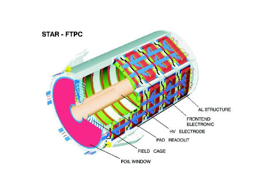
The FTPC concept was determined mainly by two considerations: Firstly by the high particle density with tracks under small angles with respect to the beam direction and secondly by the restricted available space inside the TPC [3], where the FTPCs are located. In Fig. 1 the final design is shown. It is a cylindrical structure, 75 cm in diameter and 120 cm long, with a radial drift field and readout chambers located in 5 rings on the outer cylinder surface. Each ring has two padrows and is subdivided azimuthally into 6 readout chambers. The radial drift configuration was chosen to improve the two-track separation in the region close to the beam pipe where the particle density is highest. The field cage is formed by the inner HV-electrode, a thin metalized plastic tube, and the outer cylinder wall at ground potential. The field region at both ends is closed by a planar structure of concentric rings, made of thin aluminum pipes. The front end electronics (FEE), which amplifies, shapes, and digitizes the signals, is mounted on the back of the readout chambers. Each particle trajectory is sampled up to 10 times. The ionization electrons are drifted to the anode sense wires and induced signals on the adjacent cathode surface are read out by 9600 pads (each 1.620 mm2). The above design has some unusual and new features for a TPC:
-
•
The electrons drift in a radial electrical field perpendicular to the solenoidal magnetic field.
-
•
Curved readout chambers are used to keep the radial field as ideal as possible.
-
•
A two-track separation of 1-2 mm is expected, which is an order of magnitude better than in all previously built TPCs with pad readout.
To meet these requirements a R+D program was initiated, including the selection of the most suitable gas mixture, the development of the fabrication technology for the curved readout chambers, and the optimization of the wire and pad geometry for the readout chambers.
2.2 Selection of Gas Mixture
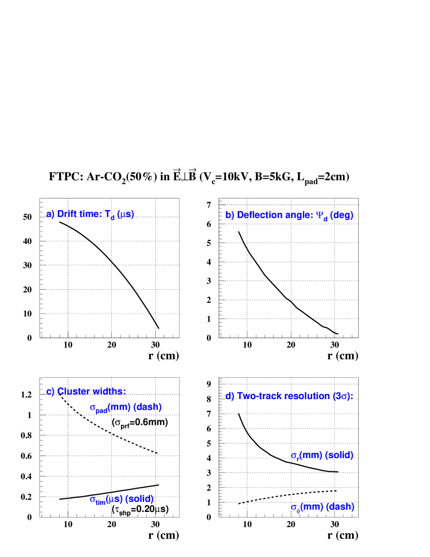
Due to the short drift length of only 23 cm a cool gas mixture with CO2 or DME can be used. It has a low diffusion coefficient for electrons and a small Lorentz angle [4]. After extensive measurements an Ar/CO2 () mixture was selected which is nonflammable, shows no or little ageing effect in comparison to hydrocarbons and is chemically less agressive than a mixture with DME. Fig. 2 shows the measurements of drift time, cluster sizes, deflection angle due to the Lorentz force in the magnetic field and two track resolution for the Ar/CO2 gas mixture [1].
2.3 Readout Chambers
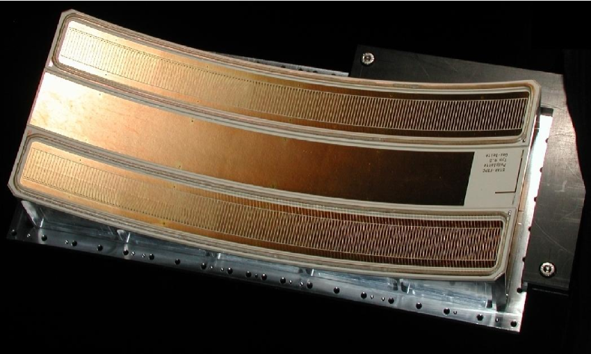
In a conventional TPC the anode (amplification) wires are orthogonal to the axial direction of the pads. This is impossible in the case of a curved readout chamber. The wires can not be parallel to the pads and therefore to the cylinder axis either, because focusing effects then lead to periodic shifts in the position measurement. This is demonstrated in fig. 3. However, if two or more wires cross the pad under a small angle this effect already vanishes. For the FTPC design an angle of 17.40 was chosen resulting in three wires crossing each pad for the selected pad-wire geometry. The anode wires are first glued on the flat pad plate with conductive epoxy. Afterwards the plate is bent between 3 rollers to the final curvature without breaking the wires. A complete readout chamber with 2 padrows is shown in fig. 4. With only 1.5 mm distance between the anode wires and the pad plane the spread of the signal (the so-called Pad Response Function) is of similar narrow width. This together with the low electron diffusion and the radial drift principle results in the required 2-track separation of about 1 mm as can be seen in fig. 5.


2.4 Readout Electronics
The two FTPCs have 19,200 channels of electronics, capable of measuring the charge drifting to the readout chambers in short time samples. The drift time of about 50 s for the 23 cm maximum drift length is subdivided into 256 time bins. Because of the slow drift gas and the resulting long duration of the collection of the electron cloud from a track crossing a shaping time of 350 ns is used. The sampling rate is 5 MHz. The design of the front end electronics closely follows that of the central TPC [5]. Each pad is read out by a low-noise STAR preamplifier/shaper (SAS), which sends signals to a switched capacitor array/ADC chip (SCA/ADC). Four of these chip sets, handling 64 channels, are mounted on a small FEE card, which is positioned directly on the detector, parallel to the readout chambers. Fifteen FEE cards are read out by a readout board, which sends the signals via a 1.2 Gbit/s fiber-optic link to the data acquisition system. The readout board also controls the FEE cards, utilising signals from the clock and trigger distribution system, and the slow control links. For maintaining the proper operating temperature the FEE and readout boards are water cooled using a leakless, low pressure circulation system [9]. The FTPCs are remotely operated through a VME based supervision system. Data logging and visualisation are performed by a software package developed within the EPICS mainframe [10].
2.5 Laser Calibration System
A laser calibration system serves the following primary purposes:
-
•
Provides straight ionized tracks of known position to infer corrections for spatial distortions caused by mechanical or drift field imperfections.
-
•
Helps to calibrate the drift velocity in the non-uniform radial drift field.
-
•
Tests the detector independent of collider operation.
The design of this system, similar to the STAR-TPC laser system [6], uses a frequency quadrupled Nd:YAG laser to provide a UV (266 nm) beam. The beam is expanded to 30 mm, split and transported via mirrors to the two FTPC detectors. Remote angle control of two mirrors in each path plus a CCD readout maintains precise steering of the two beams to the detectors. At the detector the beam is subdivided with pickoff mirrors into 3, 8 mm beams which pass into the gas volume through fused silica windows. Each of these beams are further split with smaller pickoff mirrors into 5, 1 mm beams, producing a total of 15 fiducial, ionizing beams distributed in the active volume.
3 Simulation and Reconstruction of Experimental Data
The first step in the reconstruction of tracks is to calculate the track points (cluster finding) from the charge distribution measured by the readout electronics. In a second step (track finding), these track points are grouped to tracks. Using the magnetic field map, the up to ten position measurements per track are then used to fit the momentum.
3.1 Cluster Finding
The reconstruction of track points is done by the FTPC cluster finding program [7]. It is optimized to deal with high track densities while minimizing the use of computing time. The program reads in the electronic signal data from the data acquisition system, looks for areas of nonzero charge (cluster), deconvolutes clusters and fits the point coordinates. The transformation from pad position and drift time into cartesian coordinates includes the correction of distortions introduced by the magnetic field. For a typical central Au+Au collision with 1000 particles in both FTPCs and an occupancy of in the inner region the program needs about 2 seconds on a 930 MHz Intel PentiumII processor.
3.2 Track Reconstruction
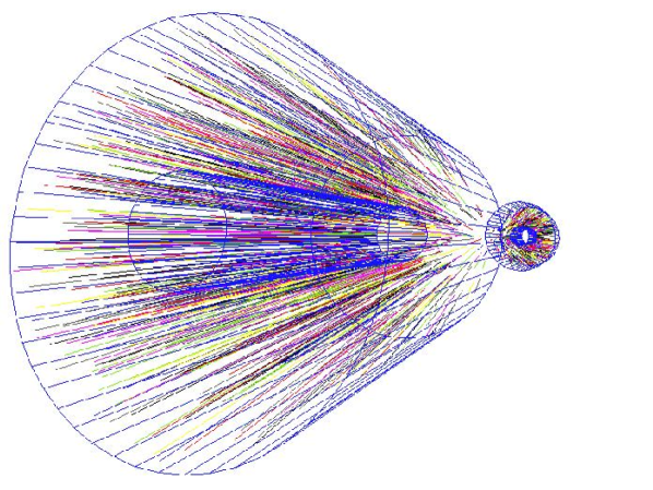
The second step in the analysis of FTPC data is the reconstruction of the particle tracks and their momenta. The FTPC track reconstruction code is based on an algorithm developed for fast online reconstruction [8]. It is a conventional track-following algorithm optimized for minimum use of computing power. In this code all position calculations are done in a transformed coordinate system in which points appear on a straight line if they form a helix in cartesian coordinates. This processing step is known as conformal mapping [8]. It saves calculation time in the track fitting, because all fits can be done by linear regression. After the track finding step the code determines a primary vertex position by extrapolating and intersecting all the reconstructed tracks. Finally the particle momenta are fitted using the magnetic field map and the vertex position. Fig. 6 shows a reconstructed HIJING event for a central Au+Au collision at 200 GeV per nucleon pair. From 14,745 space points 1,026 particle tracks were reconstructed in less than 2 seconds.
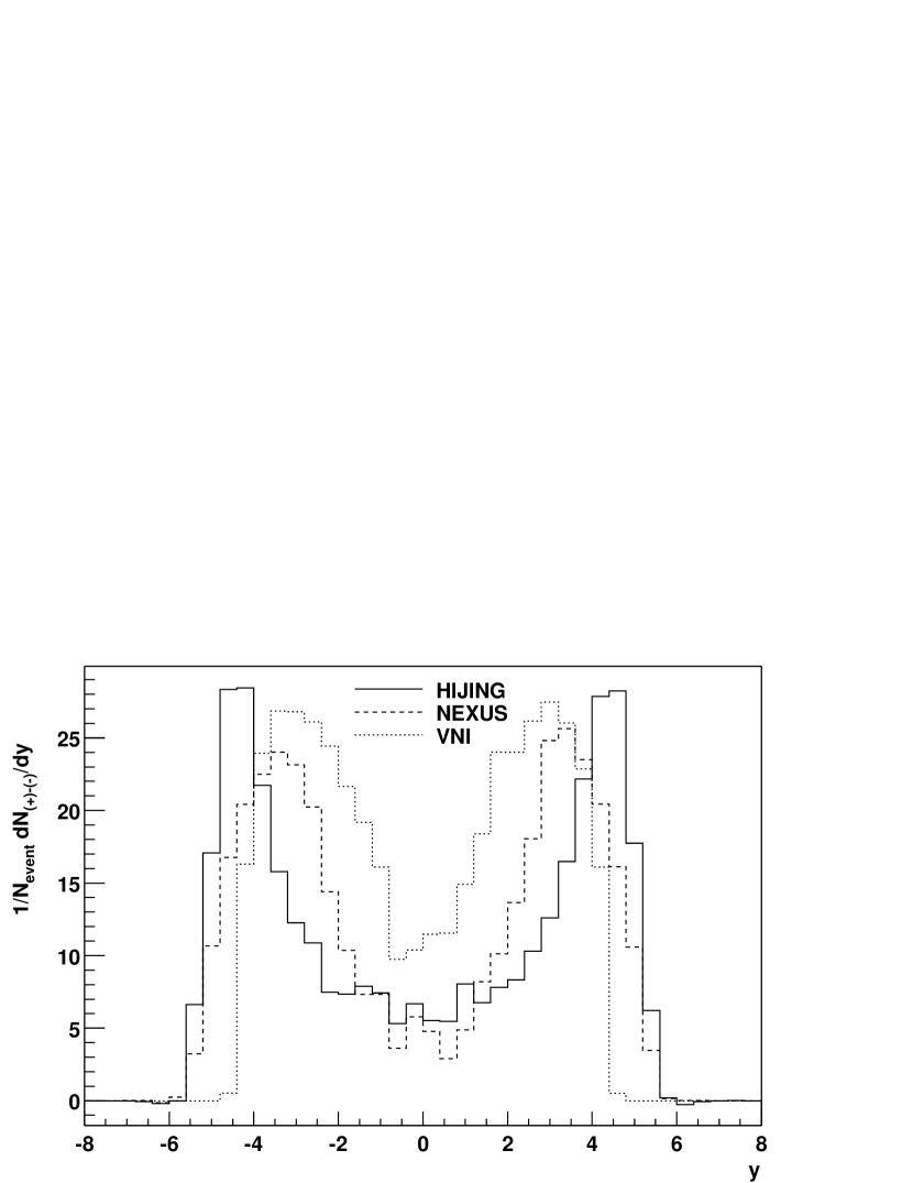
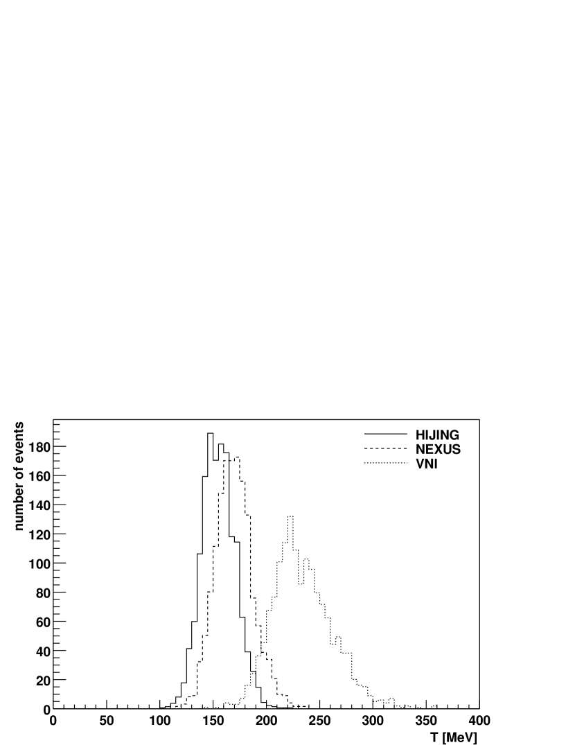
4 Physics Simulation Studies
Simulation studies demonstrate the capability of distinguishing different theoretical models of nucleus-nucleus collisions such as HIJING, NEXUS and VNI with measurements in the FTPCs. Fig. 7 shows the rapidity distribution of net positive charges which follow the p - distribution and characterise the baryon stopping in the reaction. Fig. 8 shows histograms of the effective temperature as determined event-by-event. Such measurements will be used to study and search for fluctuations of event properties and to select special event classes.
5 Summary
Based on the prototype measurements and simulations one expects to obtain a position resolution of 100 m, a two-track-separation of 1mm, a momentum resolution between 12 and 15 , and an overall reconstruction efficiency between 70 and 80 .
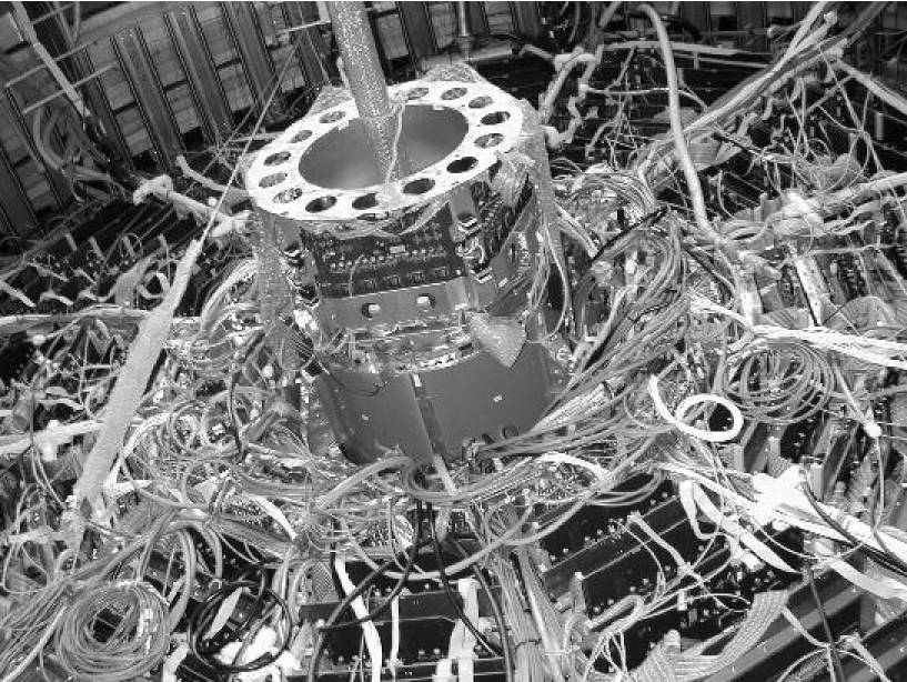
A summary of the main characteristics of the FTPCs is given in table 1. The completed and tested FTPCs have been installed in the STAR experiment for first data taking during summer and fall of 2001. One of them can be seen mounted inside the STAR detector in Fig. 9.
| PARAMETER | VALUE |
|---|---|
| Configuration | |
| # of TPC | 2 |
| rows per TPC | 10 |
| sectors per pad row | 6 |
| pads per sector | |
| Sensitive Volume | |
| inner radius | 8.0 cm |
| outer radius | 30.5 cm |
| chamber length | 120.0 cm ( cm) |
| acceptance | |
| Field Cage | |
| drift cathode voltage | 10-15 kV |
| drift electrical field | 240-1400 V/cm (radial) |
| solenoid magnetic field | 0.5 T |
| Gas | |
| gas mixture | Ar(50%)-CO2(50%) |
| drift velocity | 0.3 - 2.0 cm/s |
| trans. diffusion | 100-130 m/ |
| long. diffusion | 100-130 m/ |
| Lorentz angle | 4 deg. (at 0.5 T) |
| gas gain | 1-2 |
| Readout | |
| # of pads | 19200 |
| time bins per pad | 256 |
| pad pitch | 1.9 mm |
| pad length | 20 mm |
| anodewire–pad gap | 1.5 mm |
| shaping time (FWHM) | 350 ns |
| SCA time bin size | 218 ns |
| ADC dynamic range | 10 bits |
References
- [1] F. Bieser et al., The Forward Time Projection Chamber for the STAR Detector, MPI PhE/98-3, 1998
- [2] A. Schüttauf et al., A Forward TPC for STAR, Nucl. Phys. A 661 (1999) 677c
- [3] H. Wieman et al., STAR TPC at RHIC, IEEE Trans. Nucl. Sci. 44 (1997) 671
- [4] X. Bittl et al., Diffusion and Drift Studies of Ar-DME/CO2/CH4 Gas Mixtures for a radial TPC in the EB Field, Nucl. Instr. Meth. A 398 (1997) 249
- [5] S. Klein et al., Front-End Electronics for the STAR TPC, IEEE Trans. Nucl. Sci. 43 (1996) 1768
-
[6]
M. Alyushin et al., Laser Calibaration System for STAR TPC,
IEEE Nucl. Sc. Symp. Conference Record 96CH35974 (1996),
Proceedings of the 9th Vienna Conference on Intrumentation, Nucl. Instr. Meth. in print -
[7]
H. Hümmler, Doctorate Thesis, Technical University,
München, Germany, 2000, MPI PhE/2001-04 2001,
H. Hümmler, Simulation and Reconstruction of Data from the STAR FTPC, STAR Note SN0429 (2000) -
[8]
P. Yepes, A fast track pattern recognition, Nucl. Instr. Meth. A 380 (1996) 582
M.Oldenburg, Doctorate Thesis, Technical University, München, Germany, 2001, in preparation - [9] M. Bosteels, Cern internal report, CERN/LHCC/99-33 (1999)
- [10] A.J. Kozubal et al., ICALEPS89 Proceedings, 288, (Vancouver, 1989)