Fjords in viscous fingering: Selection of width and opening angle
Abstract
Our experiments on viscous fingering of air into oil contained between closely spaced plates reveal two selection rules for the fjords of oil that separate fingers of air. (Fjords are the building blocks of solutions of the zero-surface-tension Laplacian growth equation.) Experiments in rectangular and circular geometries yield fjords with base widths , where is the most unstable wavelength from a linear stability analysis. Further, fjords open at an angle of . These selection rules hold for a wide range of pumping rates and fjord lengths, widths, and directions.
pacs:
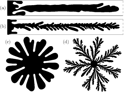
47.54.-r, 47.20.Ma, 68.35.JaSimilar growth patterns have been found for viscous fingering, bacterial growth, flame propagation, dielectric breakdown, electrodeposition, solidification, metal corrosion, and diffusion-limited aggregation (DLA) Couder (2000). Analyses of these interfacial patterns is daunting because of the broad range of length scales, as illustrated by our experiments on fingering of air in thin oil layers (Fig. 1). The interface becomes increasingly ramified with increasing forcing strength, which is characterized by the capillary number
| (1) |
where is the viscosity of the oil, is the local interfacial velocity, and is the surface tension of the air-oil interface.
Most theoretical work on viscous fingering has concentrated on fingers rather than fjords, but fjords have been considered as building blocks of a theory of Laplacian growth in an analysis of a two-dimensional inviscid fluid penetrating a viscous fluid (with zero interfacial tension) Mineev-Weinstein and Dawson (1994). The exact solutions for the interface are free of finite-time singularities and are linear combinations of logarithmic terms, each term representing a single straight fjord with parallel walls. While these analytic solutions have helped in the understanding of the growth of complex growth patterns, experiments indicate fjords can have curved trajectories and nearly always have a nonzero opening angle (Fig. 1) Lajeunesse and Couder (2000).
Most experiments have also concentrated on fingers, but a few experiments have examined fjords Lajeunesse and Couder (2000). For the circular sector (“wedge”) geometry, Thomé et al. measured the angular gap between a wall and a divergent finger (at a point 12 cm from the vertex) to be approximately 5∘ for divergent sector angles between and Thomé et al. (1989). Their sector decomposition method considered finger growth in terms of wedges whose “virtual walls” were fjord centerlines; this approach suggests that a fjord opening angle should be about , i.e. twice the angle measured by Thomé et al. Thomé et al. (1989). Theoretical analysis BenAmar (1991); Tu (1991) yielded an estimate corresponding to a fjord opening angle of Tu (1991). Other work has suggested that the width of a fjord relative to the width of the splitting finger has values between and Thomé et al. (1989); Paterson (1981); Pereira and Elezgaray (2004); Lajeunesse and Couder (2000).
Despite much effort, selection laws are lacking for ramified fingers in either rectangular [Figs. 1(a) and 1(b)] or circular geometries [Figs. 1(c) and 1(d)]. We find that fjords in both geometries have a well-defined base width that is determined by the characteristics of the interface at the fjord’s birth (when a finger splits). Further, we find that fjords open at an angle that is close to . The selection rules for the fjord width and opening angle hold for a wide variation in the ramification of the patterns.
Experimental apparatus — Interfacial patterns were grown in both rectangular and circular Hele-Shaw cells (closely spaced glass plates) filled with oil. Air was forced into the oil, creating an unstable interface (Fig. 1). In the rectangular geometry, two pieces of glass (each 1.91 cm thick), separated by a gap of 0.0508 cm, bounded a cell 25.4 cm wide by 254 cm long Moore et al. (2002). The maximum variation in gap thickness at the center of the cell (due to the imposed pressure gradient) was less than 3% even at the highest pump rate Moore et al. (2002). The cell was filled with silicone oil (viscosity mPa s and surface tension mN/m at 24 ∘C); the oil wets the glass completely. A uniform flow rate was achieved using a syringe pump to withdraw oil from a reservoir at one end of the channel; an air reservoir at atmospheric pressure was attached to the other end. The channel was illuminated from below. Each full interface, as in Figs. 1(a) and 1(b), was constructed from 11 images (each pixels, 0.21 mm/pixel), which were obtained using a camera and rotating mirror. Alternatively, the camera was focused on a fixed 22-cm-long section of the channel to obtain a time resolution of 12 frames/s [Fig. 2(a)].
In the radial geometry, air was forced into an oil-filled gap through a hole in the center of the bottom glass plate. Each optically polished glass plate had a diameter of 28.8 cm and a thickness of 6.0 cm. The two plates were separated by a gap thickness of 0.0127 cm (uniform to 1%) Sharon et al. (2003); Praud and Swinney (2005). The gap and an annular reservoir were filled with silicone oil (viscosity mPa s and surface tension mN/m at 24 ∘C). Interfacial patterns were grown either by maintaining a constant pressure difference between the oil reservoir and air or by using a syringe pump to remove oil from the buffer. Images of resolution 0.32 mm/pixel were acquired at up to 12 frames/s.
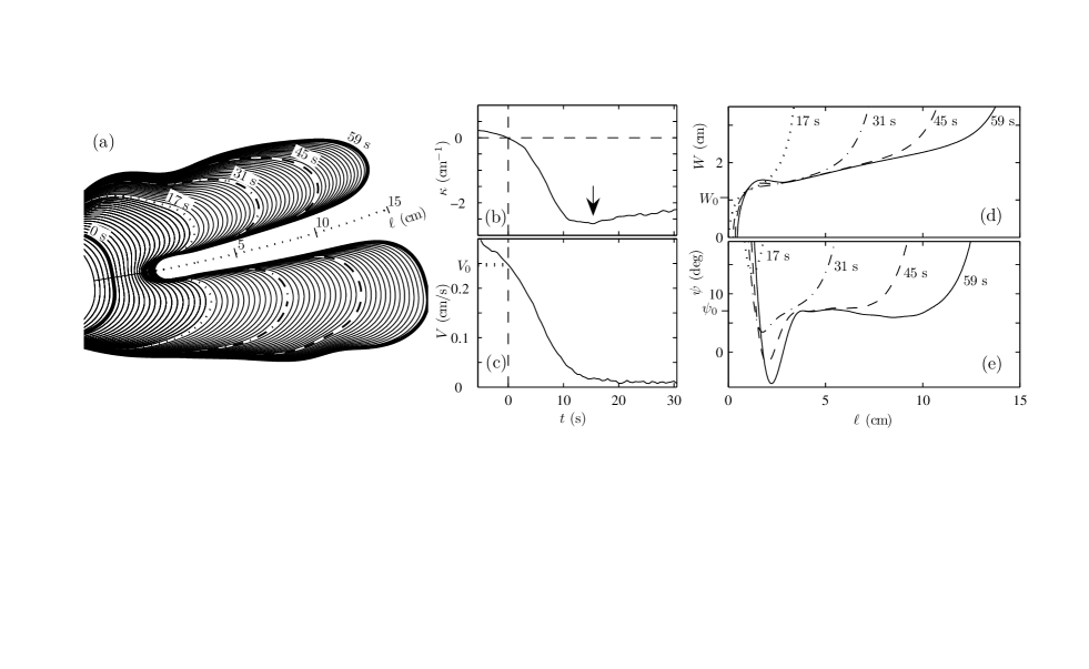
Fjord characteristics — From the images we determined, as a function of time, the interface’s velocity and curvature , the fjord width , and the fjord opening angle (Fig. 2). The most unstable (critical) wavelength of a curved interface between a less viscous fluid forced into a more viscous fluid is given by Chuoke et al. (1959); Bataille (1968)
| (2) |
where is the cell gap thickness and is the interface curvature (not including the curvature in the small gap dimension) at the point where the finger becomes unstable Park and Homsy (1984); Schwartz (1986); Chen (1989); foo (a). For all interfaces that we examined, the curvature term in Eq. (2) was about two orders of magnitude smaller than the term involving the capillary number Ca; hence we made the flat interface () approximation in computing .
When a finger became unstable, the finger flattened and a fjord was born. A normal projection algorithm was used to track the fjord trajectory back in time to earlier interfaces [solid, nearly straight line on the left in Fig. 2(a)]. (The fjord location for an earlier interface was identified by projecting a ray normally from the later interface until it intersected the earlier one.) The time evolution of the local curvature then revealed the birth of the fjord, where [Fig. 2(b)]. The velocity at this point [Fig. 2(c)] was used in Eq. (2) to calculate . The uncertainty in is 9%; film wetting corrections Schwartz (1986); Park and Homsy (1984) and the velocity measurements are the main sources of uncertainty.
Once a fjord developed, we determined its width as a function of the arc length of its centerline, as illustrated in Fig. 2(d). The fjord centerline was found by beginning with a point on the side of the fjord; then the closest point on the opposite side was found such that the interior angles between the two local tangents and the line connecting the two points were the same. The midpoint of the connecting line gave a point on the fjord centerline. Repeating this procedure for each point on the side of the fjord constructed the centerline. The fjord base point () was taken to correspond to the minimum of curvature along the fjord’s trajectory [Fig. 2(b)]. As surface tension relaxed the interface, a fjord’s base moved forward. The distance a base moved after was corrected by adding the same distance to the arc length [Fig. 2(d)].
Curves obtained for different fjords exhibited the same structure: initially grew quickly with increasing due to the rounded nature of the fjord base, but soon increased linearly with . The fjord base width was measured as follows: for each the local tangent of was linearly extrapolated back to , a histogram of extrapolated base widths was made, and the histogram’s peak gave . For an individual fjord measured over a wide range of times, this procedure yielded a fjord base width with a typical uncertainty of 6%. Confinement by neighboring fjords caused a slightly increasing extrapolated fjord base width with increasing values of .
The observed linear increase in suggested an almost constant opening angle: . The angle had the same qualitative evolution for all fjords: a fjord began with an opening angle of 180∘, followed by a surface-tension-induced dip, followed by a peak and a plateau (usually with a slightly negative slope), and finally a rapid increase at the fjord’s end [Fig. 2(e)]. We defined the opening angle to be the peak of the histogram of values generated from plots of . The angle selected was always about ; the uncertainty in the opening angle for a single fjord was 0.5∘.
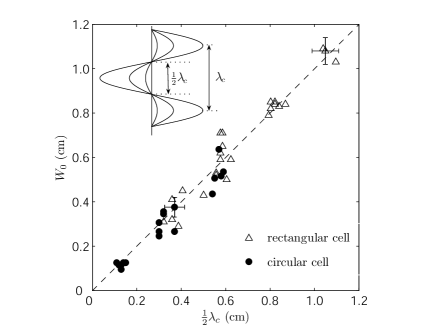
Fjord base width — We predict that the base width of a fjord is determined at the onset of the instability of the moving interface, as illustrated by the inset of Fig. 3. The critical wavelength given by a linear stability analysis of the infinitesimally perturbed flat front, Eq. (2), determines the distance between adjacent fingers when they are born, and the base width of the macroscopic fjord that develops between the two emergent fingers is . A comparison between measurements and the predicted widths requires a value for the velocity in the expression for the capillary number Ca. Lajeunesse and Couder suggest that a perturbation on a finger is the “precursor” of tip splitting and confirm that the perturbation’s wavelength is “of the order of 1.5 Lajeunesse and Couder (2000).” Our approach tests this idea at the instability’s onset, making the assumption that is measured at the point on the fjord’s trajectory corresponding to [Figs. 2(b) and 2(c)].
Measurements of the fjord base widths in both the circular and rectangular geometries agree well with the predicted widths, as Fig. 3 illustrates. The fjord widths varied by an order of magnitude as the control conditions were varied widely (pump rates were 0.17 - 2.00 cm3/s in the rectangular cell and 0.000 83 - 0.033 cm3/s in the circular cell, and in the latter geometry, measurements were also made for pressure differences of 0.10 and 0.25 atm). The local forcing strength at the birth of a fjord is affected by nearby fjords, walls, and details of the interface, so a given global pumping rate can yield fjords with different properties. The uncertainties in and are 9% and 6%, respectively. The observed scatter in Fig. 3 is consistent with these estimated errors.
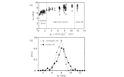
Fjord opening angle — The opening angle measured in the rectangular geometry is shown in Fig. 4(a) as a function of the appropriate forcing parameter for this geometry, the modified capillary number (where is the channel width) Park and Homsy (1985); Moore et al. (2002), which was computed using the average velocity of the farthest finger tip. Isolated fjords occur in the regime just beyond the onset of tip splitting, which occurs for Park and Homsy (1985); foo (b).
For 25 000, the pattern develops a high density of fjords. Despite the wide range of experimental parameters in this regime, the measured angles are surprisingly similar. The results for the distribution of opening angles in the circular cell are indistinguishable from those for ramified patterns in the rectangular cell: the probability distribution function has the same form with essentially the same mean 8∘ and same standard deviation 1∘ [Fig. 4(b)]. We suggest that the near constancy of the opening angle is fundamental to scale invariance and fractal dimension. Our result is consistent both with efforts to relate the multifractal dimensions of a fully developed fingering structure Mathieson et al. (2005) with the fjords’ opening angle Sarkar (1990) and with a recent observation Praud and Swinney (2005) of an invariant unscreened angle distribution in a fractal grown in a radial geometry. While intriguing, the connection between these invariant geometrical characteristics remains obscure.
Conclusions — We have presented two selection rules for the geometric form of fjords in rectangular and circular cells. The base width selected by the fjords has been found to be well described by , where is the local critical wavelength. This selection rule provides insight into the most apparent difference in viscous fingering patterns: highly forced patterns are composed of thinner fjords. The rule is based on universal features of Laplacian growth and does not invoke any specific properties of viscous fingering in a Hele-Shaw cell. Therefore, we conjecture that this rule should apply not only to viscous fingering, but also to other isotropic Laplacian growth problems.
The second selection rule is obtained from measurements of the opening angle as a function of arc length along the fjord centerline: for a broad range of experimental parameters and for both circular and rectangular geometries, the selected opening angle was always near 8∘; we have no explanation for this result. The two selection rules hold for a wide range of fjord widths, lengths, and degrees of bending, and for a wide range of angles of fjord directions with respect to the rectangular cell axis or with respect to radial lines in the circular cell.
We thank W. D. McCormick, M. Moore, O. Praud, and J. Swift for helpful discussions. This work was supported by an Office of Naval Research Quantum Optics Initiative Grant and by a Los Alamos National Laboratory LDRD Grant.
References
- Couder (2000) Y. Couder, Perspectives in Fluid Dynamics, edited by G. K. Batchelor, H. K. Moffat, and M. G. Worster (Cambridge University Press, Cambridge, U.K., 2000), pp. 53–104.
- Mineev-Weinstein and Dawson (1994) M. B. Mineev-Weinstein and S. P. Dawson, Phys. Rev. E 50, R24 (1994).
- Lajeunesse and Couder (2000) E. Lajeunesse and Y. Couder, J. Fluid Mech. 419, 125 (2000).
- Thomé et al. (1989) H. Thomé, M. Rabaud, V. Hakim, and Y. Couder, Phys. Fluids A 1, 224 (1989).
- BenAmar (1991) M. BenAmar, Phys. Rev. A 43, R5724 (1991).
- Tu (1991) Y. Tu, Phys. Rev. A 44, 1203 (1991).
- Paterson (1981) L. Paterson, J. Fluid Mech. 113, 513 (1981).
- Pereira and Elezgaray (2004) A. Pereira and J. Elezgaray, Phys. Rev. E 69, 026301 (2004).
- Moore et al. (2002) M. G. Moore, A. Juel, J. M. Burgess, W. D. McCormick, and H. L. Swinney, Phys. Rev. E 65, 030601(R) (2002).
- Sharon et al. (2003) E. Sharon, M. G. Moore, W. D. McCormick, and H. L. Swinney, Phys. Rev. Lett. 91, 205504 (2003).
- Praud and Swinney (2005) O. Praud and H. L. Swinney, Phys. Rev. E 72, 011406 (2005).
- Chuoke et al. (1959) R. L. Chuoke, P. van Meurs, and C. van der Pol, Trans. AIME 216, 188 (1959).
- Bataille (1968) J. Bataille, Rev. Inst. Fr. Pét. Ann. Combust. Liq. 23, 1349 (1968).
- Park and Homsy (1984) C.-W. Park and G. M. Homsy, J. Fluid Mech. 139, 291 (1984).
- Schwartz (1986) L. Schwartz, Phys. Fluids 29, 3086 (1986).
- Chen (1989) J.-D. Chen, J. Fluid Mech. 201, 223 (1989).
- foo (a) In previous work, Chen Chen (1989) measured the instability wavelength as a function of Ca. Park and Homsy Park and Homsy (1984) and Schwartz Schwartz (1986) calculated corrections due to the surface tension and film wetting.
- Park and Homsy (1985) C. W. Park and G. M. Homsy, Phys. Fluids 28, 1583 (1985).
- foo (b) The isolated fjords have a selected opening angle , which is lower than the angle measured in fjords grown with 25 000. These fjords are strongly confined by the walls.
- Mathieson et al. (2005) J. Mathieson, I. Procaccia, M. Thrasher, and H. L. Swinney, unpublished (2005).
- Sarkar (1990) S. K. Sarkar, Phys. Rev. Lett. 65, 2680 (1990).