Uniaxial magnetocrystalline anisotropy in
Abstract
is a paramagnetic metal and since its low temperature resistivity is described by with , it is also considered a non-Fermi liquid (NFL) metal. We have performed extensive magnetoresistance and Hall effect measurements of untwinned epitaxial films of . These measurements reveal that exhibits uniaxial magnetocrystalline anisotropy. In addition, the low-temperature NFL behavior is most effectively suppressed when a magnetic field is applied along the easy axis, suggesting that critical spin fluctuations, possibly due to proximity of a quantum critical phase transition, are related to the NFL behavior.
pacs:
72.15.Gd; 71.27.+a; 73.61.-r; 73.50.-hI Introduction
is a paramagnetic metal that attracts considerable attention due to its intriguing properties; in particular, its low temperature resistivity described by with CRONFL and its non-Drude optical conductivity CROopt . These properties suggest that is a non-Fermi liquid (NFL) metal and since proximity to a magnetic quantum critical point could be the source of this behavior, it is important to elucidate the magnetic properties of .
Here we present measurements of untwinned films and clearly demonstrate for the first time that exhibits anisotropic paramagnetic susceptibility that could be described in terms of an anisotropic susceptibility tensor with the easy axis of magnetization at 45 degrees out of the film plane. This kind of anisotropy is also exhibited by a related compound, the itinerant ferromagnet , in its paramagnetic phase SROanisotropy .
Direct magnetic measurements of magnetic properties of paramagnetic films suffer from signal weakness combined with large background signal of the substrates. Therefore, we use indirect magnetic measurements where the magnetic properties are inferred from measurements of magnetoresistance (MR) and extraordinary Hall effect (EHE).
Following the identification of the magnetic properties of films, we found that suppression of the low-temperature non-Fermi liquid behavior by external magnetic field is most efficient when the field is applied along the easy axis of magnetization; suggesting that spin fluctuations are related to the NFL behavior.
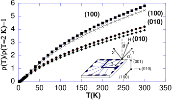
Our samples are patterned thin films grown either on or on . The measurements presented here are of a 100 nm - thick film of grown on slightly miscut substrate with resistivity ratio of . Resistivity measurements of four different patterns on the same film reveal correlation between resistivity curves and current direction (Figure 1). This indicates that in the films grown on miscut substrates the intrinsic anisotropy is not averaged by twinning. Similar methods, enabled growing of untwinned films. For convenience, we note in the following the miscut direction as the (010) direction of the substarte.
II Measurements
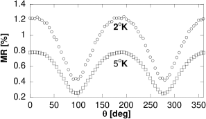
The magnetic anisotropy of is manifested in MR measurement shown in Figures 2 and 3. The MR is measured as a function of (See Figure 1) which is the angle between the applied field and the normal to the film with the axis of rotation (100) (Figure 2) or (010) (Figure 3). We note that at low temperatures the MR is positive while at high temperatures the MR is negative. Although the temperature at which the MR changes its sign and the values of the MR depend on the current direction and the magnetic field direction, the patterns with current paths along different directions exhibit nonetheless the same qualitative angular dependence: with rotation axis along (100) the graph extrema are at while with rotation axis along (010) the graph extrema are at . This indicates that the dominant source of MR is related to the orientation of the applied field relative to the epitaxial film irrespective of current direction.
The observed MR cannot be attributed to Lorentz MR. At high temperatures the MR is negative while Lorenz MR is positive. At low temperatures, the MR is positive; however, it is strongly temperature dependent, which is not expected for Lorenz MR where the resistivity hardly changes. For example between 5 K to 2 K the resistivity changes by less than while the MR changes by more than . Moreover, the estimated mean free path even in the zero temperature limit () electronicsrycture is much smaller than the cyclotron radius ().
Since Lorenz MR is excluded, we look for MR effects related to the magnetization. Although anisotropic MR is important in this material, it cannot be the dominant effect, since the qualitative angular dependence of the MR is insensitive to the current direction relative to the field. Therefore, a likely source is MR which is sensitive to the magnitude of the magnetization.
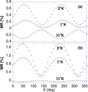
At temperatures above K the MR is negative and it can be attributed to suppression of spin fluctuations. Hence, the angular dependence of the MR reflects anisotropic susceptibility of with the easy axis at (011) and the two other principal axes at and . This explains the observation that for rotation around the graph extrema are at while rotation around yields graph extrema at .
At low temperatures the MR is positive (yet not related to Lorenz MR) and the angle of maximum negative MR at K turns into the angle of maximum positive MR at K. Since the source of the positive MR is unclear at this stage we need other measurements to determine if the maximum of positive MR also coincides with maximum magnetization. Namely, to determine whether the easy axis at K is also the easy axis at K. We thus turn to measurements of extraordinary Hall effect.
The Hall field in magnetic conductors, ferromagnetic and paramagnetic, has two contributions:
| (1) |
where B is the magnetic field, and and are the ordinary and the extraordinary Hall coefficient, respectively. The angular dependence of the ordinary Hall effect (OHE) is simple and follows the perpendicular component of . On the other hand, the EHE depends on the perpendicular component of whose magnitude depends (in the presence of uniaxial anisotropy) on the angle between the field and the easy axis. Figures 4a and 4b present the total Hall effect (HE) as a function of for (100) plane and (010) plane, respectively, for several temperatures. The ordinary Hall Effect is proportional to while the measured HE has dependence (Figure 4a); hence, OHE alone cannot explain the observed angular dependence. Similarly, EHE cannot account for the results without the magnetocrystalline anisotropy.
Quantitatively, the magnetic anisotropy is expressed by an anisotropic susceptibility tensor, with the magnetization vector given by
| (2) |
where is the susceptibility tensor with eigenvalues , corresponding to a field applied along the three principal axes. Because is in the plane of the film, our HE measurements are not sensitive to . However, MR measurements indicate that .
With this notation the dependence of the total HE on the angle of the applied field in the plane ( measured from the normal to the plane of the film) is expected to be:
| (3) | ||||
and in the plane is:
| (4) | ||||
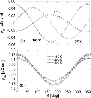
where , and (See Figure 1). The curves in Figures 4a and 4b are fits to Equations 3 and 4, respectively. As we can see, the fits are satisfactory: At all temperatures the HE in the plane behaves as while in the plane as .
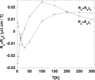
As seen in Figure 5, and are equal at K and K. There are two possible causes for the identical values: either the EHE vanishes, (), or the anisotropy vanishes, (). The angular-dependent MR at K indicates that ; hence changes its sign at K. The MR at K is too small to measure; therefore, we cannot refute either possibility. Nevertheless, the fact that magnetic anisotropy is observed at higher temperatures suggests vanishing of at 200 K.
If the two crossing points of and are both due to sign change of , it means that in the entire temperature interval that we measure . This means that in the easy axis is the direction which is in our film at angle relative to the plane of the film, as illustrated in Figure 1. The two other axes are along and directions. This means that the maximum positive MR is correlated with maximum of magnetization. We discuss below possible source of such behavior.
The temperatures at which vanishes enable convenient measurements of . Using the most naive one-band calculations , where q is the carrier charge and n is the carrier density, the estimated carrier density is of electrons at , and of holes at . Since the Hall coefficient shows both signs, both electronlike and holelike bands contribute to the conductivity.
Since proximity to a magnetic quantum critical point could be the source of the NFL behavior in , we explore the field dependance of . Figure 6 shows as a function of field when the field is applied along various directions. The largest increase of is obtained for magnetic fields applied along the easy axis, while the smallest increase is obtained for magnetic fields applied along the hard axes. These results indicate that increasing the magnetization is a route of turning into a Fermi liquid metal.
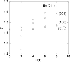
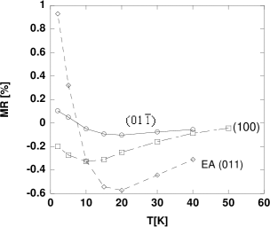
Figure 7 presents the MR with the field applied along the three principal axes as a function of temperature. As shown in Figure 2 at low temperatures the maximum of the positive MR is when the field is applied along the easy axis, , and at high temperatures the maximum of the negative MR is also obtained when the field is applied along the easy axis. These results imply that the negative MR, as well as the positive MR, are related to and not to . It is important to note that the temperature at which the MR changes its sign depends on the field and current directions.
III DISCUSSION
As mentioned above, the MR is positive at low temperatures and negative at high temperatures, and both, the negative and the positive MR are related to the magnetization and not to the magnetic field. In addition, at all temperature range . Therefore, the cause for the sign change has to be due to two mechanisms both relating the magnetization to the MR effect.
The negative MR is commonly found in magnetic metals, the applied field suppresses the spin fluctuations, thus yielding negative MR. is a paramagnetic metal. Therefore, one may expect spin contribution to resistivity and hence negative MR.
On the other hand, magnetization related positive MR is less understood. We propose that a possible source for this behavior is the correlation between magnetization and band structure. Electronic structure calculations of using the linear muffin-tin orbital method show a sharp peak in the density of states (DOS) near Fermi level electronicsrycture . Therefore, a possible source for the positive MR could be the large variations of the DOS at the Fermi energy. The conductance in metals is proportional to the density of states at the Fermi level, therefore applying a magnetic field on which at low temperature is on the edge of spontaneous splitting of the spin up and spin down bands can change the conductance of the metal. If the maximum of the DOS is at the fermi energy at zero magnetic field then applying magnetic field may reduce the DOS and hence cause positive MR.
The field-induced change in the DOS could be another factor (in addition to suppressing of critical spin fluctuations expected near quantum phase transition) in the partial recovery of Fermi liquid (FL) behavior in . In some NFL metals, like CeCuAu2 , and CeNiGe1 the FL behavior is recovered at large magnetic fields. Here at T although the FL behavior is not recovered, is getting closer to the FL value of 2.
IV acknowledgments
L.K. acknowledges support by the Israel Science Foundation founded by the Israel Academy of Science and Humanities.
References
- (1) L. Klein, L. Antognazza, T. H. Geballe, M. R. Beasley, and A. Kapitulnik, Phys. Rev. B 60, 1448 (1999).
- (2) Y. S. Lee, J. Yu, J. S. Lee, T. W. Noh, T. H. Gimm, H. Y. Choi and C. B. Eom, Phys. Rev. B 66, 41104 (2002).
- (3) Y. Kats, I. Genish, L. Klein, J. Reiner, M. R. Beasly, cond-mat/0311341 (2003).
- (4) G. Santi and T. Jarlborg, J. Phys.: Cond. Matter. 9, 9563 (1997).
- (5) H. von Lohneysen, T. Pietrus, G. Portisch, H. G. Schlager, A. Schroder, M. Sieck and T. Trappmann, Phys. Rev. Lett. 72, 3262 (1994).
- (6) F. Steglich, B. Buschinger, P.Gegenwart, M. Lohmann, R. Helfrich, C. Langhammer, P. Hellmann, L. Donnevert, S. Thomas, A. Link, C. Geibel, M. Lang, G. sparn and W. Assmus, J. Phys.: Cond. Matter. 8, 9909 (1996).