Generation of spin-wave dark solitons with phase engineering
Abstract
We generate experimentally spin-wave envelope dark solitons from rectangular high-frequency dark input pulses with externally introduced phase shifts in yttrium-iron garnet magnetic films. We observe the generation of both odd and even numbers of magnetic dark solitons when the external phase shift varies. The experimental results are in a good qualitative agreement with the theory of the dark-soliton generation in magnetic films developed earlier [Phys. Rev. Lett. 82, 2583 (1999)].
pacs:
75.30.Ds, 76.50.+g, 75.70.-i, 85.70.GeI Introduction
Dark solitons have been predicted theoretically and observed experimentally in different types of dispersive or diffractive nonlinear media, including optical and magnetic systems book . Recently, dark solitons have been generated in Bose-Einstein condensates of dilute atomic gases BEC by engineering the phase of the macroscopic wave function with a technique known as phase imprinting, earlier developed to create optical and matter-wave vortices book . Phase imprinting is a new tool of manipulating coherent matter waves, and it is described as shining an off-resonance laser on a Bose-Einstein condensate in order to create phase steps between its different parts. A given phase step defines the parameters of dark solitons travelling in the same or opposite directions, and the total number of the generated matter-wave dark solitons which can be either odd or even BEC2 .
As a matter of fact, these recent results on the generation of dark solitons in Bose-Einstein condensates can be compared with and linked to much earlier experimental studies of microwave magnetic-envelope spin-wave solitons in yttrium-iron garnet (YIG) magnetic films first . Indeed, the first observation of dark solitons in YIG magnetic films Patton revealed unusual features of the dark-soliton generation observed as a change of the total number of generated spin-wave dark solitons from even to odd with the growth of the input power. These observations have later been explained theoretically by employing the concept of the so-called induced spatial phase shift SKB , which is closely related to the concept of phase imprinting, as was also discussed in Ref. BEC2 . Recently, a further attempt to employ the phase manipulation technique for generating single and multiple dark magnetic solitons has been undertaken in Ref. Serga .
The purpose of this paper is twofold. First, we extend the concept of phase imprinting implemented for dark solitons and vortices in Bose-Einstein condensates to the field of magnetic solitons, and generate experimentally single and multiple spin-wave envelope magnetic dark solitons from rectangular dark input high-frequency pulses with externally introduced phase shifts in YIG magnetic films. Second, we provide a direct verification of the theory developed earlier in Ref. SKB .
The paper is organized as follows. In Section II we introduce our model which was first suggested in the pioneering papers first and is described by the cubic nonlinear Schrödinger (NLS) equation for the magnetic field envelope. Section III summarizes the basic theoretical results for the generation of dark solitons by an input pulse with a jump across the low-intensity region SKB . The main Sec. IV presents our experimental results which are shown to be in a good agreement with the basic theoretical predictions.
II Model
We consider the evolution of a spin wavepacket in the form , where the slowly varying complex envelope is described by the dimensionless nonlinear Schrödinger (NLS) equation first ,
| (1) |
where is the group velocity evaluated from the spin-wave nonlinear dispersion at the carrier wavenumber , is the coefficient of linear dispersion, and is the coefficient of nonlinearity. In the derivation of Eq. (1) dissipation is neglected first .
In the case , Eq. (1) has a solution in the form of a dark soliton that can be written as follows HasTap :
| (2) |
where . Solution (2) describes a localized dip in the continuous wave (CW) background with the half-width , the center , and the velocity . In the phase factor of the dark solitons, is the soliton wave number and is the soliton frequency shift, which are the nonlinearity-induced corrections to the wavenumber and carrier frequency .
Solution (2) is a special case of a dark soliton with a modulation factor , i.e. when the dark soliton has a minimum amplitude of (the so-called “black soliton”). Due to the -function, this soliton has an overall phase shift of . However, such pulses usually do not appear in experimental situations. Instead, a more general form of a dark soliton HasTap should be used,
| (3) |
where the phase factor has the form:
| (4) | |||
Solution (3) describes a single “grey soliton” with an arbitrary value of the modulation depth . For , Eq. (3) transforms into the ”black” soliton (2).
The important condition for such dark solitons to exist is the phase shift given by Eq. (4) that has to be present in the carrier wave book . In the experimental situation, there is no such total phase shift and, therefore, only even-numbered symmetric pairs of dark solitons with equal modulation can be generated. In these pairs, the phase shifts of the individual dark solitons have opposite signs and they compensate one another, so the total phase shift adds up to vanish, . Under such conditions, excitation of odd numbers of dark solitons seems, in general, impossible book .
III Theoretical background
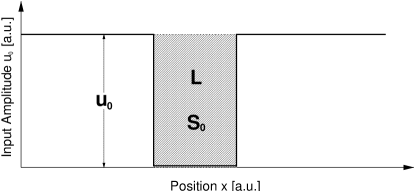
Recently, it was shown analytically and numerically that when an input pulse without any initial phase modulation enters a nonlinear dispersive medium, the generated localized wave acquires an induced spatial phase shift accumulated during its generation SKB . Such a phase shift is negligible for large group velocities, e.g., for optical solitons in fibers, but it becomes important for spin waves in magnetic films. Moreover, if the initial phase shift (Fig. 1) is included in the inverse scattering transform zakharov , the results can be employed to explain SKB the specific features of the generation of both odd and even numbers of dark solitons observed in experiment Patton .

In order to demonstrate the role of the initial phase shift, we summarize the results for the dark-soliton generation in the framework of the normalized NLS equation,
| (5) |
Equation (5) follows from Eq. (1) after rescaling, by assuming the reference frame moving with the group velocity , and renormalizing the variables and . The input pulse is characterized by the phase shift and the dimensionless value , which is defined as and is usually called the input pulse area as it is proportional to the carrier wave amplitude multiplied by (spatial) pulse length . The soliton wavenumber shift can then be presented as .
According to Ref. SKB , the number and symmetry of the excited sequence of dark solitons are defined by the transcendental equation for the soliton eigenvalue ,
| (6) |
Every solution of this equation for the real eigenvalue corresponds to a dark soliton with the modulation depth , where has the dimension of the renormalized amplitude, . The right-hand side of Eq. (6) is always point-symmetric around the origin whereas for the -function this is only the case when is zero phasendefinition . In this latter case, Eq. (6) yields pairs of eigenvalues with the same absolute value but with opposite signs. This explains why only even-numbered symmetric pairs of dark solitons are predicted by the earlier theory zakharov . Note that a dark soliton with zero amplitude minimum is defined by , i.e. at . This is only the case for and odd multiples thereof.


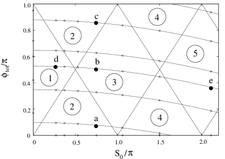
A finite initial value of the phase shift allows to predict the generation of asymmetric or symmetric, odd- or even-numbered dark soliton pulses. The typical structure of an =3-soliton state and the corresponding variation of its phase are schematically shown in Fig. 2. Such a soliton sequence is characterized by the overall number of dark solitons and the modulation of each individual dark soliton. According to Eq. (6), these values are completely determined by the input pulse area and the total phase shift . This suggests SKB the use of the parameter plane as presented in Fig. 3. Changing the pulse length and/or input amplitude is equivalent to moving on the horizontal axis. A change in the total phase shift is denoted by a shift on the vertical axis. Every point in that parameter plane can be assigned a value of and , therefore it is directly connected to a dark soliton of distinct eigenvalues .

In Ref. SKB , it was shown that in physical systems with low values of the group velocity, an additional phase shift is acquired during the process of pulse excitation. However, in the general case, the total phase shift in the input pulse carrier wave may originate either from the pulse forming setup, i.e. it is provided externally, or from an intrinsic mechanism in the physical system. In this paper, we present a systematic study of the formation of magnetic dark solitons with a variable external phase shift . Using these data, we verify, in particular, whether an acquired phase shift is present at all and whether it fits the theoretically expected values.
In essence, the results of Ref. SKB predict that an additional phase shift acquired during the process of dark-soliton generation can be written in the form,
| (7) |
where is the (positive) dispersion time. The phenomenological factor (introduced in the theory SKB and evaluated there to be close to 2) takes into account the influence of the finite length of the background CW signal.
Usually, the sign of would not be important due to the symmetry of Eq. (6). However, as we are using a phase shifter in the experiment to produce the external phase , the relative sign of these two phase shifts is important. In the experiments described below, the sign of the acquired phase shift was opposite to that of the external phase shift . Thus, the total phase shift of the input pulse is expressed as
| (8) |
where is determined by Eq. (7). Note that there is always a fixed ‘offset‘ phase shift, even in the limit . This means that all dark solitons in magnetic systems acquire a phase shift during the process of their generation. However, if the group velocity and, therefore, is large, as we have for the case of dark solitons in optics book , the phase is small and will remain unimportant. In this case, the dark solitons are always placed on a horizontal line at on the -plane which is equivalent to the production of even-numbered symmetric pairs of dark solitons.
If the input pulse parameters are in a range that , the acquired phase shift may manifest itself by producing asymmetric and/or odd-numbered dark solitons, and the points corresponding to these solitons on the parameter plane of Fig. 3 will belong to the parabolic curve defined by Eq. (7) and having a minimum at the point =0. This case was realized in the pioneering experiments performed by Patton’s group Patton .
On the other hand, if the constant and positive external phase shift is introduced externally, while duration of the input pulse is kept constant and the input wave amplitude (and, therefore, ) is increased, the dependence has the form of a quadratic parabola with a maximum at =0 [see Eq. (8)]. As will be seen below, it is this case that is realized in our current experiments. Therefore, the points corresponding to different output solitonic pulses obtained in our experiments with a positive external phase shift and increasing input wave amplitude belong to parabolas having a maximum at =0 (see Fig. 6 below).
IV Experimental results
To study the effects produced by an external phase shift on the generation of magnetic dark solitons, we need to design an experimental setup with the following characteristics: (i) the setup should include a nonlinear dispersive waveguide capable of supporting spin-wave dark solitons, i.e. the necessary condition for the formation of dark solitons, , should be fulfilled; (ii) the parameters of the pulses propagating in the waveguide should fit the range where the induced phase shift defined by the Eq. (7) has a large enough value and could be detected experimentally; (iii) there should be a technical possibility to introduce an external phase shift between the leading and trailing fronts of the input pulse, similar to the phase shift introduced by the method of phase imprinting in Bose-Einstein condensates or nonlinear optics book .
For our experiments, we have chosen magnetostatic spin waves propagating in a thin quasi-one-dimensional waveguide made of a single-crystal YIG film. Nonlinear properties of these waves are well understood, and the formation of both dark and bright solitons has been observed first ; Patton . Moreover, the measurement techniques incorporating the so-called delay line setup are well established. In our case, it is especially important that one can easily introduce an external phase shift in the input pulse simply using a microwave phase shifter. The most important feature of the magnetostatic waves in the context of this study is their comparatively low group velocity that should result in a substantial value of the induced phase shift defined by Eq. (7)(see Ref. SKB for details).
The experiments are performed on a 1.5 mm wide and 7m thick YIG film waveguide which, due to its relatively small width, could be considered as quasi one-dimensional. The film waveguide is fixed in a standard delay line setup consisting of two strip-line antennas of 45m width and 9.2 mm separation. A microwave frequency of 5.065 GHz is used. A magnetic bias field of 1107.5 Oe strength is applied tangentially to the film surface and perpendicularly to the propagation direction of spin waves and, therefore, the conditions for the excitations of magnetostatic surface waves are fulfilled. The value of the magnetic field is chosen so as to place the working point frequency in the middle of the spin-wave spectrum, letting all Fourier components of the dark-pulse signal pass through.
A variable phase shift in the input pulse is created in the following way: a continuous microwave signal produced by a sweep-generator is divided into two parts, which are then individually controlled by microwave modulators connected to the pulse generators. A standard microwave phase shifter is introduced in one of the modulation channels. Then, the two resulting pulse-modulated signals are combined together in a microwave mixer device, and are supplied to the input antenna of the experimental delay line (see Fig. 4).


In the experimental scheme described above, the trailing edge of the bright rectangular pulse created in the first modulation channel provides the leading edge of the input dark pulse, while the leading edge of the bright rectangular pulse created in the second modulation channel provides the trailing edge of the input dark pulse. The phase shift is introduced by the variable phase shifter inserted in the second modulation channel. Thus, the duration of the formed dark input pulse (see Fig. 5) is determined by the difference of the time delay between the leading edges of both bright rectangular pulses and the duration of the bright pulse in the first modulation channel . The duration of the input dark pulses in our experiment could be changed in 1 ns steps, and the duration of the CW background before and after the input dark pulse is controlled by changing the durations and in the first and second modulation channels, respectively. In our experiments, the values of and are chosen to be constant and equal, = = 1s. The input pulse sequences of the form shown in Fig. 5 are produced with a repetition rate of about 100 kHz.
The magnitude of the external phase shift introduced into the dark input pulse is controlled by the variable phase shifter in the second modulation channel. The zero point and the scale calibration of the phase shifter are established by adjusting it to the points of minimum and maximum interference of two overlapping pulses. The sign of the phase shift is established by calibrating it at different frequencies.
The signal is recorded with a digital oscilloscope and a transient recorder (500 MHz) through a diode detector. The signal received by the output antenna is amplified using a low-noise small-signal amplifier to drive the detector diode in its optimum sensitivity range and to achieve the highest signal-to-noise ratio possible. The output voltage in this range is proportional to the power at the input of the detector diode.
In our experiment the variable parameters are: (i) input power , (ii) duration of the dark input pulse , and (iii) external phase shift . The input power is varied in the interval mW, while the dark pulse duration is varied in the interval ns in steps of 5 ns. We use the following values of the external phase shift: 0.17, 0.42, 0.6, 0.72, and 0.95.
The experimental results are summarized using the parameter plane of Fig. 3. The profiles of the output pulses corresponding to the fixed values of the input power , dark input pulse duration , and external phase shift are recorded, and the corresponding points are placed on the parameter plane Fig. 3. Counting the number of the minima in the output pulse profile corresponding to a particular set of input parameters, we can determine the number of solitons and compare it with the theory.
However, to compare the experimental results with the theory, the dispersion and nonlinearity parameters of the magnetostatic waves propagating in the YIG film waveguide should be either measured or calculated. First, the group velocity at the working point is determined by measuring the time of the pulse propagation between the input and output antennae of the setup. This velocity is found to be equal to cm/s () which is close to the theoretical estimate of the group velocity of cm/s () obtained from Eq. (55) in Ref. Wigen .
The value of dispersion was established by comparing at several frequencies MHz above and below the carrier frequency . Using a polynomial fit function of , the value of at the working point was determined to be cms (). The large error is due to the small differences of at small frequency intervals. The theoretical estimation of the dispersion coefficient done using Eq. (55) from Ref. Wigen gives the value of . Thus, in the calculations below we use the values: cm/s () and cms ().
The value of the nonlinearity coefficient could not be measured directly. Thus, it was calculated using Eq. (52) from Ref. Wigen to give .
The results of our experiments for the pulse duration of = 20 ns are presented in Fig. 6. Two adjustable parameters are used to place the experimental points on this graph. The first parameter is the coefficient relating the input power to the normalized amplitude of the spin wave , i.e. = . It defines the relation between the input power and the parameter used in the theoretical formula (7) and, therefore, it determines the scale of the graph along the horizontal axis. Similar to Ref. SKB , we chose assuming that at the input power of mW, when thermal effects begin to manifest themselves, we have a typical value of the spin wave amplitude in the film equal to = 0.07 (see Ref. Dudko ). For the conditions of our experiment this yields , which is about three times larger than the similar value in Ref. Patton . The difference may be attributed to a better matching between the impedances of the supply line and the input micro-strip antenna.
The second adjustable parameter is the phenomenological coefficient in Eq. (7) which describes the effect of a finite CW background of the input dark pulse and determines the scale of the graph in Fig. 6 along the vertical axis. Similar to Ref. SKB , we take .
The parabolas presented in Fig. 6 are computed using Eq. (8), and they correspond to different values of the external phase shift 0.17, 0.42, 0.60, 0.72, and 0.95, so that the lowest parabola corresponds to the smallest external phase shift of 0.17. The values of the initial (linear) phase shifts corresponding to the initial point are computed as
| (9) |
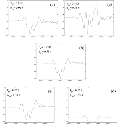
The points on the parabolas correspond to the points where the experimental oscillograms of the output signal are recorded. Samples of such experimental oscillograms corresponding to the points denoted by letters ”a”, ”b”, ”c”, ”d” and ”e” in Fig. 6 are presented in Fig. 7. The left row of oscillograms demonstrates that, when the external phase shift grows from 0.17 to 0.95 but the input power is constant (i.e., ), the output signal profile with (a) two dark solitons transforms into (b) three dark solitons, and then again into (c) two dark solitons.
The right row of oscillograms in Fig. 7 demonstrates that with an increase of the input power at a fixed value of the external phase shift 0.6, the number of dark solitons is increasing as the output oscillograms contain either one, three, or five dark solitons. These results appear to be in a good qualitative agreement with the theory SKB .
We should mention that the number of dark solitons observed in the experimental profiles does not always match the number predicted by the theory SKB . This is especially true for very small and very large values of the input power. For small values of , corresponding to the values , the dark soliton is not properly formed as the time of the signal propagation between the antennae is smaller than the so-called ”nonlinear time” during which the spin-wave nonlinearity could significantly affect the pulse profile. On the other hand, for large values of corresponding to , nonlinear dissipation and other nonlinear effects, not taken into account in our simple theoretical model, make the dependence of on the input power nonlinear, which prevents us from making a quantitative comparison between theory and experiment. At the same time, it is clear from the experimental data presented above that in the range of the intermediate input powers, 0.5, the theory gives a good qualitative and even reasonable quantitative explanation of the experimental data.
In conclusion, we have extended the concept of phase engineering, demonstrated earlier for matter-wave dark solitons in Bose-Einstein condensates, to spin-wave magnetic solitons. We have demonstrated experimentally the crucial role played by an externally introduced phase shift in the input pulse for the process and outcome of the dark-soliton generation. Our experimental results are in a good qualitative agreement with the analytical and numerical predictions of dark-soliton generation, and they provide more direct verification of the theory.
Acknowledgements
We thank Carl Patton and Elena Ostrovskaya for useful discussions. This project was supported by the Deutsche Forschungsgemeinschaft, the Alexander von Humboldt Foundation, the MURI grant W911NF-04-1-0247 of the US Army Research Office, and the Australian Research Council.
References
- (1) Yu.S. Kivshar and G. P. Agrawal, Optical Solitons: From Fibers to Photonic Crystals (Academic, San-Diego, 2003), 540 pp; and references therein.
- (2) S. Burger, K. Bongs, S. Dettmer, W. Ertmer, K. Sengstock, A. Sanpera, G.V. Shlyapnikov, and M. Lewenstein, Phys. Rev. Lett. 83, 5198 (1999).
- (3) B. Wu, J. Liu, and Q. Niu, Phys. Rev. Lett. 88, 034101 (2002).
- (4) See, e.g., B.A. Kalinikos, N.G. Kovshikov, and A.N. Slavin, JETP Lett. 38, 413 (1983); M.A. Tsankov, M. Chen, and C.E. Patton, J. Appl. Phys. 76, 4274 (1994); J.M. Nash, C.E. Patton, and P. Kabos, Phys. Rev. B 51, 15079 (1995); A.N. Slavin, H. Benner, K.J. Foos, and T. Lesperance, J. Phys. (Paris) 7, C1-459 (1997).
- (5) M. Chen, M.A. Tsankov, J.M. Nash, and C.E. Patton, Phys. Rev. Lett. 70, 1707 (1993).
- (6) A.N. Slavin, Yu.S. Kivshar, E.A. Ostrovskaya, H. Benner, Phys. Rev. Lett. 82, 2583 (1999).
- (7) A.A. Serga, A. Andre, S.O. Demokritov, B. Hillebrands, and A.N. Slavin, J. Appl. Phys. 95, 6607 (2004).
- (8) A. Hasegawa, and F. Tappert, Appl. Phys. Lett. 23, 171 (1973).
- (9) V.E. Zakharov and A.B. Shabat, Zh. Eksp. Teor. Fiz. 64, 1627 (1973) [Sov. Phys. JETP 37, 823 (1973)].
- (10) In Ref. SKB the definition of the phase shift is slightly different. Here, only input pulses with zero intensity in the dark part are considered, and simplified phase jump was chosen in order to avoid confusion.
- (11) Note the factor ”2” between theoretical and experimental phase shifts kept to avoid confusion with SKB .
- (12) P.E. Wigen, Ed., Nonlinear Phenomena and Chaos in Magnetic Materials (World Scientific, Singapore, 1994), pp. 225-226.
- (13) A.N. Slavin and G.M. Dudko, J. Magn. Magn. Mater. 86, 115 (1990).