Cryptanalyzing an improved security modulated chaotic encryption scheme using ciphertext absolute value
Abstract
This paper describes the security weakness of a recently proposed improved chaotic encryption method based on the modulation of a signal generated by a chaotic system with an appropriately chosen scalar signal. The aim of the improvement is to avoid the breaking of chaotic encryption schemes by means of the return map attack introduced by Pérez and Cerdeira. A method of attack based on taking the absolute value of the ciphertext is presented, that allows for the cancellation of the modulation scalar signal and the determination of some system parameters that play the role of system key. The proposed improved method is shown to be compromised without any knowledge of the chaotic system parameter values and even without knowing the transmitter structure.
keywords:
Chaos, cryptography, nonlinear systems, security of data, telecommunication.PACS:
05.45.Ac, 47.20.Ky.., , , .
1 Introduction
The possibility of synchronization of two coupled chaotic systems was first shown by Pecora and Carrol [1, 2, 3]. The importance of this discovery was quickly appreciated [4, 5], and soon this topic aroused great interest as a potential means for communications [6, 7, 8]. In recent years, a considerable effort has been devoted to extend the chaotic communication applications to the field of secure communications. Accordingly, a number of cryptosystems based on chaos has been proposed [9, 10, 11, 12, 13]; some of them fundamentally flawed by a lack of robustness and security [14, 15, 16, 17, 18].
Pérez and Cerdeira showed in [19] that it was possible to retrieve the data encrypted by chaos when a parameter of the sender is switched between two values. The data were recovered directly from the ciphertext signal, without using the authorized receiver and even without reconstructing the dynamics of the chaotic system, by means of the attractor of a return map. Later this method was further developed by Yang et al. in [20].
Recently Bu and Wang [21] proposed an improved chaotic encryption method. The aim of the improvement is to foil the return map attack to chaotic encryption schemes of [19, 20]. The proposed approach is illustrated by means of a Lorenz system, described by the following equations:
| (1) |
being , and the system internal parameters.
In the literature, when digital encryption takes place, the signal is commonly taken as the transmitted encrypted message. The authors of [21] propose as ciphertext the modulation signal .
The modulation signal should be an appropriately chosen scalar signal. For the Lorenz dynamical system they propose to choose as the product of a sinusoidal factor times a variable of the chaotic system: . Hence, the transmitted ciphertext will be: .
The key of the system is composed by the unknown values of the system internal parameters together with the, so called, external parameters and , thus considerably enlarging the key space with respect to the simple chaotic encryption.
The authors of [21] show that the attractor of the return map of the ciphertext is blurred by the modulation and, consequently, they claim that an intruder can not retrieve any information from it. They also show that the Fourier power spectrum of the ciphertext does not allow for the knowledge of the frequency of the sinusoidal factor.
The authors seem to base the security system on the impossibility of performing a return map attack and determining the sinusoidal modulating signal; but no general analysis of security is included. The weaknesses of this system and a method to break it are discussed in the next section.
2 Ciphertext absolute value attack
In this section is presented an attack to the proposed improved security encryption scheme based on taking the absolute value of the ciphertext. Our attack allows for the system breaking in two different ways. The first one consists of retrieving the plaintext directly from the ciphertext, when digital encryption is used. The second one consists of the identification and cancelation of the modulating signal , allowing the plaintext recovery by the return map attack, thus circumventing the alleged system security improvement.
The Lorenz attractor has a complicated shape, with trajectories spiralling around, and jumping between two loops, either in three dimensions or in any two-dimension projection.
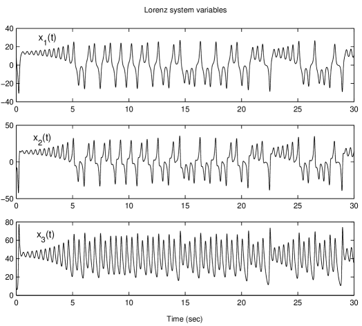
It is interesting to look at the time story and frequency power spectrum of each component of the Lorenz system. As illustrated in Fig. 1, the variable shows a quasi sinusoidal oscillation, always of positive value, whose amplitude changes in an irregular sawtooth like fashion; while the variables and show a similar behavior but with sudden large amplitude jumps across the zero axis, corresponding to the attractor jumps between loops.
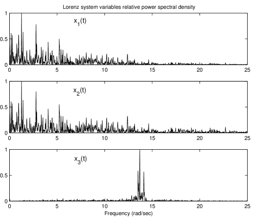
The frequency power spectra of the Lorenz system variables are illustrated in Fig. 2. As observed, has a relative clean and simple spectrum, with a narrow band at 13.7 rad/sec, that corresponds to the stable frequency of its oscillatory waveform. However, the variables and have a much broader and complex spectra, with maximum amplitude near 3 rad/sec, due to the aperiodic jumps across the zero axis.
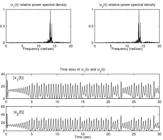
Let us take the absolute value of the two first Lorenz system variables: , . When computing the time stories and frequency power spectra of and the results illustrated in Fig. 3 are obtained. Both time stories resemble very much that of , while their frequency power spectra are practically indistinguishable from that of . That is, a new set of signals and has been built, whose waveform and spectra are much simpler than the ones of the original variables. In fact, when substituting or with or the double scroll is converted into a simple scroll with quite regular motion.
It is assumed in the literature that chaotic modulation is an adequate means for secure transmission, because chaotic maps present some properties as sensitive dependence on parameters and initial conditions, ergodicity, mixing, and dense sinusoidal points. These properties make them similar to pseudorandom noise [22], which has been used traditionally as a masking signal for cryptographic purposes.
A fundamental requirement of the pseudorandom noise used in cryptography is that its spectrum should be infinitely broad, flat, and of higher power density than the signal to be concealed within. In other words, any information power spectrum should be buried into the pseudorandom noise power spectrum.
If any of the Lorenz system variables or is used as a carrier signal for secure transmission, an attacker can take its absolute value to build a new signal with much simpler shape and spectrum. This new signal does not satisfy the above conditions. As a consequence, it may still preserve some plaintext information within, certainly alleviating the task of breaking the system.
2.1 Direct plaintext recovery
The main problem with this kind of cryptosystems lies on the fact that the ciphertext is an analog signal, whose waveform depends on the system parameter values. When a parameter is switched between two different values by a digital plaintext [23], the system changes between two different attractors with different waveforms, amplitudes and frequencies. Therefore it is possible to extract some information by a suitable signal processing of the ciphertext.
To illustrate the possibility of breaking the system, the chaotic transmitter of [21, §2 and fig. 4] has been simulated with the same parameter values of the example, that is: , being the parameter changed between its reference value when the values 0’s are to be transmitted and when the values 1’s are to be transmitted. The parameter values have been arbitrarily chosen as: and the system initial conditions as: . Our simulation was done with a four order Runge-Kutta integration algorithm in MATLAB 6 with a step size of .
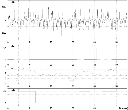
To break the system a so called full wave amplitude detector has been implemented, consisting of taking the absolute value of the ciphertext signal . Next, this signal is low-pass filtered and, finally, binary quantized. The low-pass filter employed is a six pole Butterworth with a frequency cutoff of 1 rad/sec. The quantizer is a level comparator with switch point at level value 8 of the low-pass filtered absolute value of the ciphertext signal.
The procedure is illustrated in Fig. 4. The result is a good estimation of the plaintext, with tiny inaccuracies consisting of small delays in the transitions, due to the time delay introduced by the filter. It should be emphasized that our analysis is a blind detection, made without the least knowledge of what kind of non-linear time-varying system was used for encryption, nor its parameters values and neither its keys.
2.2 Modulating signal cancellation
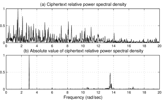
In the encryption method proposed in [21] the ciphertext signal shows a crowded frequency power spectrum as is illustrated in Fig. 5(a). As the authors point out, it is impossible to identify in it any separated factor that can be exploited to attack the system. This is a consequence of the use of the Lorenz system and the modulating procedure. First, the spectrum of is a complicated one, due to the chaotic nature of the Lorenz system. Second, the multiplication of this signal by has the effect of generating a new spectrum composed by the superposition of two versions of the spectrum shifted radians per second. And third, the value chosen for falls in the neighborhood of the maximum of the spectrum of , hence it is impossible to identify it from the frequency power spectrum.
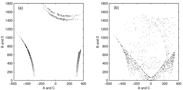
The aim of this encryption method is to foil the return map attack, by blurring the attractor of the return map. In Fig. 6 the attractor of the transmitted signal is plotted when digital encryption takes place in two different cases. In Fig. 6(a) without sinusoidal factor:
| (2) |
and in Fig. 6(b) when the sinusoidal factor is present:
| (3) |
where , being the system parameters for encryption . It can be seen that when there is no sinusoidal modulation factor it is possible to use the return map attractors to retrieve the plaintext, because it is clearly distinguishable the splitting of the attractor segments originated by the plaintext presence. But when there is a sinusoidal modulating factor the attractors happen to by fully blurred, obstructing any straightforward analysis.
To break such encryption scheme the following procedure is proposed, which will allow for the reconstruction of the return map attractor.
First the frequency of the sinusoidal factor is identified from the ciphertext by computing the Discrete Fourier Transform of the ciphertext absolute value. Let be the approximate value of and the approximate value of . As is illustrated in Fig. 5(b) it can be seen that there is a very neat pick in the spectrum exactly at rad/sec, which corresponds to the double of the sinusoidal factor frequency. This is due to the non linear nature of the absolute value function, which has the effect of folding the ciphertext upwards around the zero axis, effectively doubling the frequency of the sinusoidal factor. The part of the spectrum corresponding to the Lorenz system factor, , appears as a band of frequencies near 13.7 rad/sec. Finally, there are two small amplitude side bands at rad/sec, corresponding to the cross-modulation between the sinusoidal modulation factor and the Lorenz system factor. The spectrum was calculated using a 16384 point Discrete Fourier Transform with a 4-term Blackman-Harris window.
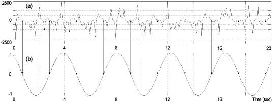
Once the sinusoidal factor frequency is estimated, it is a trivial task to determine its phase just searching for the ciphertext zero crossing points at intervals equal to , as depicted in Fig. 7.
Next, the approximate cancellation of the sinusoidal factor must be performed. Let and be the approximate values of and . Should the determination of and be exact it would be satisfactory to divide the ciphertext signal s(x,t) by the estimated sinusoidal factor to get rid of it, as:
| (4) |
But, in practice, small inaccuracies in the determination of can lead to a division by cero, with infinite amplitude error. If the error is radians it would be better to add some constant value around the zero level of the estimated sinusoidal factor, as follows:
| (5) |
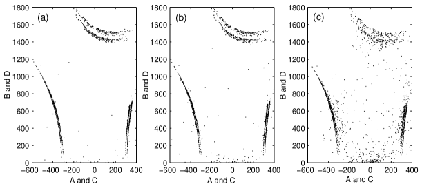
Finally, once the cancellation of the sinusoidal modulation has been performed, the return map attractor can by plotted. After simulating the reconstruction of the return map attractor of the example of 2.1, the results are presented in Fig. 8. It can be seen that the return map attractor is reconstructed with enough accuracy to enable the return map attack described in [19, 20], thus deceiving the improved security claimed by the authors of [21]. In our simulation Eq. (4) was used to reconstruct the attractor with a determination error value of radians; while for errors values of radians, equivalent to 0.06 and 0.6 degree, Eq. (5) was used, with values of 0.001 and 0.005, respectively.
3 Conclusion
The lack of security of the encryption method proposed in [21] is made evident, since it can be broken without knowing its parameter values and even without knowing the transmitter’s precise structure. A new method that can retrieve the plaintext and determine part of the key directly from the ciphertext has been devised. As a result of our attack, the security of the proposed encryption scheme does not improve over the traditional chaotic encryption methods, being still vulnerable to the same attacks it intends to foil.
References
- [1] L. M. Pecora and T. L. Carroll. Synchronization in chaotic systems. Phys. Rev. Lett., 64:821–824, 1990.
- [2] L. M. Pecora and T. L. Carroll. Driving systems with chaotic signals. Phys. Rev. A, 44:2374–2383, 1991.
- [3] T. L. Carroll and L. M. Pecora. Synchronizing chaotic circuits. IEEE Trans. Circ. and Systems CAS, 38:453–456, 1991.
- [4] R. He and P. G. Vaidya. Analysis and synthesis of synchronous periodic and chaotic systems. Phys. Rev. A, 46:7387–7392, 1992.
- [5] S. Boccaletti, J. Kurths, G. Osipov, D. L. Valladares, and C. S. Zhou. The synchronization of chaotic systems. Phys. Rep.- Rev. Sec. Phys. Lett., 366(1-2):1–101, 2002.
- [6] H. Dedieu, M. P. Kennedy, and M. Hasler. Chaos shift keying: Modulation and demodulation of a chaotic carrier using self-synchronizing Chua’s circuits. IEEE Trans. Circ. and Systems - II, 40(10):634–642, 1993.
- [7] L. Kocarev and T. Kapitaniak. On an equivalence of chaotic attractors. J. Phys. A, 28(9):L249–L254, 1995.
- [8] C. K. Tse and F. C. M. Lau, editors. Chaos-Based Digital Communication Systems: Operating Principles, Analysis Methods, and Performance Evaluation. Springer Verlag, Berlin,New York, 2003.
- [9] K. M. Cuomo and A. V. Oppenheim. Chaotic signals and systems for communications. In Proc. IEEE ICASSP III, pages 137–140, 1993.
- [10] K. M. Cuomo and A. V. Oppenheim. Circuit implementation of synchronized chaos with applications to communications. Phys. Rev. Lett., 71(1):65–68, 1993.
- [11] C. W. Wu and L. O. Chua. A simple way to synchronize chaotic systems with applications to secure communication systems. Int. J. of Bifurcation and Chaos, 3(6):1619–1627, 1993.
- [12] R. Lozi and L. O. Chua. Secure communications via chaotic synchronization. II. noise reduction by cascading two identical receivers. Int. J. of Bifurcation and Chaos, 3(5):1319–1325, 1993.
- [13] T. Yang. A survey of chaotic secure communication systems. Int. J. Comp. Cognition, 2:81–130, 2004.
- [14] K. M. Short. Steps toward unmasking secure communications. Int. J. of Bifurcation and Chaos, 4(4):959–977, 1994.
- [15] Ch.-S. Zhou and T. l. Chen. Extracting information masked by chaos and contaminated with noise: Some considerations on the security of communication approaches using chaos. Phys. Lett. A, 234:429–435, 1997.
- [16] G. Álvarez, F. Montoya, M. Romera, and G. Pastor. Cryptanalysis of a chaotic secure communication system. Physics Letters A, 306:200–205, 2003.
- [17] G. Álvarez, F. Montoya, M. Romera, and G. Pastor. Cryptanalysis of a discrete chaotic cryptosystem using external key. Physics Letters A, 319:334–339, 2003.
- [18] G. Álvarez, F. Montoya, M. Romera, and G. Pastor. Breaking parameter modulated chaotic secure communication system. Chaos, Solitons & Fractals, 156, 2004.
- [19] G. Pérez and H. A. Cerdeira. Extracting messages masked by chaos. Phys. Rev. Lett., 74(11):1970–1973, 1995.
- [20] T. Yang, L. B. Yang, and C. M. Yang. Cryptanalyzing chaotic secure communications using return maps. Phys. Lett. A, 245(6):495–510, 1998.
- [21] S. Bu and B.-H. Wang. Improving the security of chaotic encryption by using a simple modulating method. Chaos Solitons and Fractals, 19:919–924, 2004.
- [22] R. L. Devaney. A first course in chaotic dynamical systems. Addison-Wesley, Reading, MA,, 1992.
- [23] U. Parlitz, L. O. Chua, Lj. Kocarev, K. S. Halle, and A. Shang. Transmission of digital signals by chaotic synchronization. Int. J. of Bifurcation and Chaos, 2:973–977, 1992.