[
Spatial Semiconductor-Resonator Solitons
Abstract
We demonstrate experimentally and numerically the existence of spatial solitons in multiple-quantum-well semiconductor microresonators driven by an external coherent optical field. We discuss stability of the semiconductor-resonator solitons over a wide spectral range around the band edge. We demonstrate the manipulation of such solitons: switching solitons on and off by coherent as well as incoherent light; reducing the light power necessary to sustain and switch a soliton, by optical pumping.
pacs:
PACS 42.65.Sf, 42.65.Pc, 47.54.+r]
I Introduction
Spatial resonator solitons theoretically predicted in [1, 2, 3, 4, 5] can exist in a variety of nonlinear resonators, such as lasers (vortices), lasers with saturable absorber (bright solitons), parametric oscillators (phase solitons), driven nonlinear resonators (bright/dark solitons). Such resonator solitons can be viewed as self-trapped domains of one field state surrounded by another state of the field. The two different field states can be a high and a low field (bright/dark solitons), positive and negative field (phase solitons), right-hand and left-hand polarized field (polarization solitons) or high and zero field (vortices).
Bright solitons in laser resonators with saturable absorber were initially shown to exist in [6], which was limited to single stationary solitons. Existence of moving solitons and simultaneous existence of large numbers of stationary solitons was shown in [7, 8]. Phase solitons in degenerate parametric wave mixing resonators were predicted in [9] and demonstrated in [10]. Theoretically it was shown in [11] that not only 2D spatial resonator solitons exist but that also in 3D such structures can be stable, linking the field of optical solitons with elementary particle physics [12]. Vortex solitons differ from other soliton types in that they possess structural stability in addition to dynamical stability, the only stabilizing mechanism of the other solitons. The existence of vortices in lasers initially shown in [13] and later also the existence of vortex solitons [14].
Since the resonator solitons are bistable and can be moved around they are suited to carry information. Information can be written in the form of a spatial soliton, somewhere, and then transported around at will; finally being read out somewhere else; possibly in conjunction with other solitons. In this respect the spatial resonator solitons have no counterpart in any other kind of information-carrying elements and lend themselves therefore to operations not feasible with conventional electronic means, such as an all-optical pipeline storage register (”photon buffer”) or even processing in the form of cellular automata. Experiments on the manipulation of bright solitons as required for such processing tasks were first carried out on a slow system: laser with (slow) saturable absorber. In particular it was demonstrated how to write and erase solitons and how to move them or localize them. For reviews see [15, 16].
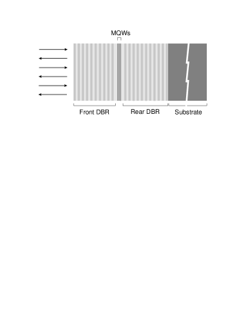
In order to be applicable to technical tasks it is mandatory to operate in fast, miniaturized systems. For compatibility and integrability with other information processing equipment it is desirable to use semiconductor systems. We chose the semiconductor microresonator structure (Fig. 1) as commonly used for vertical cavity surface emitting lasers (VCSEL) [17] consisting of multiple quantum well (MQW) structure sandwiched between distributed Bragg reflectors (DBR).
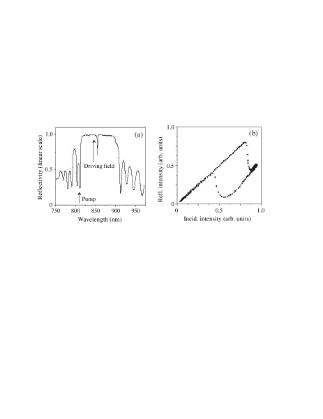
The resonator length of such a structure is while the transverse size is typically 5 cm. Therefore such short length and wide area microresonator permits only one longitudinal mode (Fig. 2 (a)) and an enormous number of transverse modes that allow a very large number of spatial solitons to coexist. The resonator is obviously of the plane mirror type, implying frequency degeneracy of all transverse modes and thus allowing arbitrary field patterns to be resonant inside the resonator. This is another prerequirement for existence and manipulability of spatial solitons.
The resonator soliton existence is closely linked with the plane wave resonator bistability (Fig. 2 (b)) caused by longitudinal nonlinear effects: the nonlinear changes of the resonator length (due to nonlinear refraction changes) and finesse (due to nonlinear absorption changes) [18]. The longitudinal nonlinear effects combined with transverse nonlinear effects (such as self-focusing) can balance diffraction and form resonator soliton. Generally these nonlinear effects can cooperate or act oppositely, with the consequence of reduced soliton stability in the later case.
In the present paper we demonstrate experimentally and numerically existence of bright and dark spatial solitons as well as extended hexagonal patterns in MQW-semiconductor microresonators at room temperature. We discuss stability of the semiconductor-resonator solitons over a wide spectral range around the band edge. We demonstrate the manipulation of such solitons in view of technical application: switching solitons on and off by coherent as well as incoherent light; reducing the light power necessary to sustain and switch a soliton, by optical pumping.
II Model and numerical analysis
We consider phenomenological model of a driven wide area MQW-semiconductor microresonator similar to [19, 20]. The optical field inside the resonator is described in mean-field approximation [21]. The driving incident field assumed to be a stationary plane wave. Nonlinear absorption and refractive index changes induced by the intracavity field in the vicinity of the MQW-structure band edge are assumed to be proportional to the carrier density (normalized to the saturation carrier density). The equation of motion for involves nonresonant (to avoid saturation effect) pumping , carrier recombination and diffusion. The resulting coupled equations describing the spatio-temporal dynamics of and have the form:
| (1) | |||
| (2) | |||
| (3) | |||
| (4) | |||
| (5) |
where is the saturable absorption scaled to the resonator DBR transmission ( is assumed to be small since the DBR reflectivity is typically 0.995). and describe the absorptive and refractive nonlinearities, respectively, is the detuning of the driving field from the resonator resonance, is the photon lifetime in the resonator scaled to the carrier recombination time, is the diffusion coefficient scaled to the diffraction coefficient and is the transverse Laplacian.
Linear effects in the resonator are spreading of light by diffraction and diffusion (terms with in (1)). The material nonlinearity that can balance this linear spreading can do this in various ways. It has a real (refractive) and imaginary (dissipative) part and can act longitudinally and transversely. The nonlinear changes of the resonator finesse (due to nonlinear absorption change) and length (due to nonlinear refractive index change) constitute longitudinal nonlinear effects, also known under the name nonlinear resonance [22]. The transverse effect of the nonlinear refractive index can be self-focusing (favorable for bright and unfavorable for dark solitons) and self-defocusing (favorable for dark and unfavorable for bright solitons). Absorption (or gain) saturation (bleaching) leading to nonlinear gain guiding in laser parlance, a transverse effect. Longitudinal and transverse effects can work oppositely, or cooperate.
There are two main external control parameters: the driving field intensity and the resonator detuning . Then for driving intensities not quite sufficient for reaching the resonance condition for the whole resonator area, the system ”chooses” to distribute the light intensity in the resonator in isolated spots where the intensity is then high/low enough to reach the resonance condition thus forming bright/dark patterns. Instead of saying ”the system chooses” one would more mathematically express this by describing it as a modulational instability (MI). The detuned plane wave field without spatial structure with intensity insufficient to reach the resonance condition is unstable against structured solutions. According to our numerical solutions of (1) a large number of such structured solutions coexist and are stable (see e.g. patterns in Fig. 7).
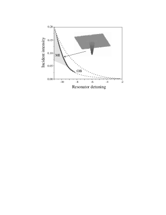
Fig. 3 shows the existence domains (in coordinates - ) of MI, dark spatial solitons and plane-wave bistability calculated for the case of purely dispersive (defocusing) nonlinearity. The dark soliton structure (inset in Fig. 3) can be interpreted as a small circular switching front. A switching front connects two stable states: the high transmission and the low transmission state. Such a front can in 2D surround a domain of one state. When this domain is comparable in diameter to the ”thickness” of the front, then each piece of the front interacts with the piece on the opposite side of the circular small domain, which can lead, particularly if the system is not far from a modulational instability (see Fig. 3), to a stabilisation of the diameter of the small domain. In which case the small domain becomes an isolated self-trapped structure or a dissipative resonator soliton.
III Experimental technique
Fig. 4 shows the optical arrangement for the semiconductor-resonator soliton experiments, and in particular for their switching on or off. The semiconductor microresonators consisting of MQW (GaAs/AlGaAs or GaInAs/GaPAs) structures sandwiched between high-reflectivity ( 0.995) DBRs (Fig. 1) operate at room temperature. The microresonator structures were grown on the GaAs substrates by molecular beam epitaxy technique that makes possible high quality MQW structures with small radial layer thickness variation. The best sample tested in our experiments has only 0.3 nm/mm variation of the resonator resonance wavelength over the sample cross section.
The driving light beam was generated by either a tunable (in the range 750-950 nm) Ti:Sa laser or a single-mode laser diode, both operating in continuous wave regime. For experimental convenience to limit thermal effects we perform the whole experiments within a few microseconds, by admitting the light through an acousto-optical modulator. The laser beam of suitable wavelength is focused on the microresonator surface in the light spot of 50 m in diameter, thus providing a quite large Fresnel number ( 100).
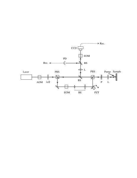
Part of laser light is split away from the driving beam and then superimposed with the main beam by a Mach-Zehnder interferometer arrangement, to serve as the address beam. The address beam is sharply focused and directed to some particular location in the illuminated. The switching light is opened only for a few nanoseconds using an electro-optic modulator. For the case of incoherent switching the polarization of the address beam is perpendicular to that of the main beam to avoid interference. For the case of coherent switching the polarizations should be parallel and a phase control of the switching field is thus always needed: for switching on as well as switching off a soliton. One of the interferometer mirrors can be moved by a piezo-electric element to control the phase difference between the driving light and the address light.
Optical pumping of the MQW-structures was done by a multi-mode laser diode or a single-mode Ti:Sa laser. To couple the pump light into the microresonator the laser wavelength was tuned into the high transmission spectral window of the microresonator reflectance spectrum as shown in Fig. 2 (a).
The observation is done in reflection by a CCD camera combined with a fast shutter (another electro-optic modulator), which permits to take nanosecond snapshots at a given time of the illuminated area on the resonator sample. Recording movies on this nanosecond time scale is also possible. To follow intensity in time in certain points (e.g. at the location of a soliton) a fast photodiode can be imaged onto arbitrary locations within the illuminated area.
IV Experimental results and discussions
To find the most stable resonator solitons for applications one can play with the nonlinear (absorptive/dispersive) response by choice of the driving field wavelength, with the resonator detuning, and finally with the carrier population inversion by the pumping. We recall that all nonlinearities change their sign at transparency i.e. at the point where in the valence- and the conduction band populations are equal. Going from below transparency (absorption) to above transparency (population inversion, producing light amplification), nonlinear absorption changes to nonlinear gain, self-focusing changes to self-defocusing and vice versa, and decrease of resonator length with intensity changes to increase (and vice versa). The population of the bands can be controlled by pumping ( in (1)) i.e. transferring electrons from the valence band to the conduction band. This can be done by optical excitation [23], with radiation of wavelength shorter than the band edge wavelength or - if the structure is suited to support electrical currents (i.e. if it is a real VCSEL-structure) - by electrical excitation.
A Below bandgap hexagons and dark solitons
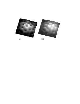
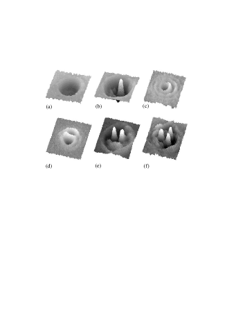
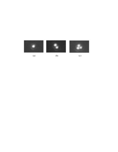
Working well bellow the bandgap when the driving field wavelength is 30 nm longer than the band edge wavelength we observed spontaneous formation of hexagonal patterns (Fig. 5). The hexagon period scales linearly with [24] indicating that they are formed by the tilted-wave mechanism [25] that is the basic mechanism for resonator hexagon formation [26]. Dark-spot hexagon (Fig. 5 (a)) converts in to bright-spot hexagon (Fig. 5 (b)) when the driving intensity increases. Experiment shows that individual spots of these patterns can not be switched on/off independently from other spots as it is expected for strongly correlated spot structure (or coherent hexagons).
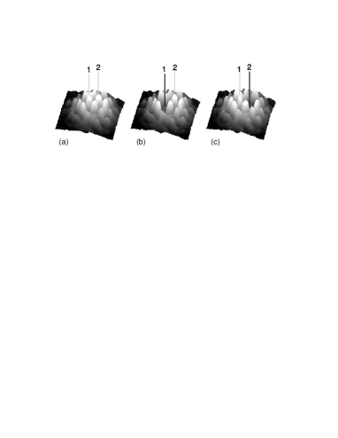
However when we further increased the driving intensity we found that the bright spots in such hexagonal patterns can be switched independently by the addressed focused optical (incoherent) pulses [24]. Fig. 6 shows the experimental results. Fig. 6 (a) shows the hexagonal pattern formed. The focused light pulse can be aimed at individual bright spots such as the ones marked ”1” or ”2”. Fig. 6 (b) shows that after the switching pulse aimed at ”1” spot ”1” is off. Fig. 6 (c) shows the same for spot ”2”. We remark that in these experiments we speak of true logic switching: the spots remain switched off after the switching pulse (if the energy of the pulse is sufficient, otherwise the bright spot reappears after the switching pulse). These observations of local switching indicate that these hexagonal patterns are not coherent pattern: the individual spots are rather independent, even at this dense packing where the spot distance is about the spot size.
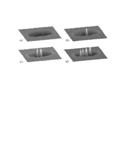
These experimental findings can be understood in the frame of the model (1) [27]. Fig. 7 shows the bistable plane wave characteristic of the semiconductor resonator for conditions roughly corresponding to the experimental conditions. At the intensities marked (a) to (d) patterned solutions exist.
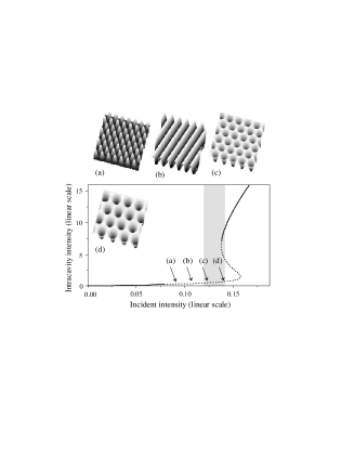
The pattern period in Fig. 7 (a) corresponds precisely to the detuning in the following way. When the driving field is detuned, the resonance condition of the resonator cannot be fulfilled by plane waves travelling exactly perpendicularly to the mirror plane. However, the resonance condition can be fulfilled if the wave plane is somewhat inclined with respect to the mirror plane (the tilted wave solution [25]). The nonlinear system chooses therefore to support resonant, tilted waves. Fig. 7 (a) is precisely the superposition of 6 tilted waves that support each other by (nonlinear) 4-wave-mixing. The pattern period corresponds to the resonator detuning as in the experiment for structures Fig. 5 (a). Thus the pattern formation in Fig. 7 (a) is mostly a linear process. In this pattern the bright spots are not independent. Individual spots cannot be switched as in the experiment Fig. 5.
On the high intensity pattern Fig. 7 (d) the pattern period is remarkably different from Fig. 7 (a) even though the detuning is the same. This is indication that the internal detuning is smaller and means that the resonator length is nonlinearly changed by the intensity-dependent refractive index (the nonlinear resonance). From the ratio of the pattern periods of Fig. 7 (a) and (d) one sees that the nonlinear change of detuning is about half of the external detuning. That means the nonlinear detuning is by no means a small effect. This in turn indicates that by spatial variation of the resonator field intensity the detuning can vary substantially in the resonator cross section. In other words, the resonator has at the higher intensity a rather wide freedom to (self-consistently) arrange its field structure. One can expect that this would allow a large number of possible stable patterns between which the system can choose.
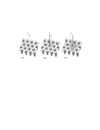
Fig. 8 shows that the high intensity conditions of Fig. 7 (d) allow reproducing the experimental findings on switching individual bright spots. Fig. 8 (a) is the regular hexagonal pattern, Fig. 8 (b) shows one bright spot switched off as a stable solution and Fig. 8 (c) shows a triple of bright spots switched off as a stable solution, just as observed in the experiments [27].
Thus while Fig. 7 (a) is a completely coherent space filling pattern, Fig. 7 (d) is really a cluster of (densest packed) individual dark solitons. The increase of intensity from (a) to (d) allows the transition from the extended patterns to the localized structures by the increased nonlinearity, which gives the system an additional internal degree of freedom. We note that the transition from the coherent low intensity pattern to the incoherent higher intensity structure proceeds through stripe-patterns as shown in Fig. 7 (b) [27]. For the intensity of Fig. 7 (c) the individual spots are still not independent as in the experiment Fig. 5 (b).
B Near bandgap bright and dark solitons
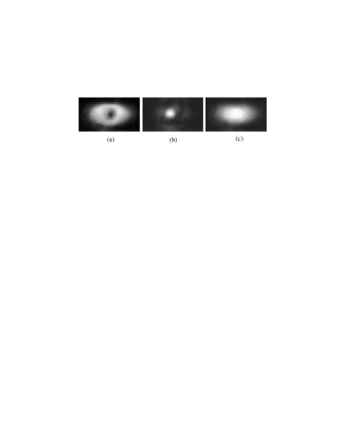
Working at wavelengths close to the band edge we found both bright and dark solitons, as well as collections of several of the bright and dark solitons, several solitons existing at the same time (Figs 9, 10). Fig. 10 demonstrates that shape and size of bright spots are independent on the shape and intensity of the driving beam that is a distinctive feature of spatial solitons.
Nonlinearity of the MQW structure near the band edge is predominantly absorptive. Therefore in the first approximation we can neglect the refractive part of the complex nonlinearity in the model equations (1) and describe the nonlinear structure as a saturable absorber. Numerical simulations for this case (Fig. 11) confirm existence of both bright and dark resonator solitons as they are observed in the experiment (Figs 9, 10). We can contrast these resonator spatial solitons with the propagating (in a bulk nonlinear material) spatial solitons: the latter can not be supported by a saturable absorber.
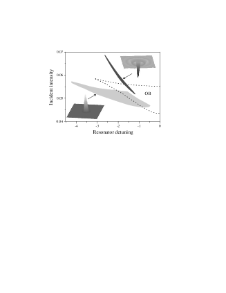
Fig. 12 (c) and (d) show details of the spontaneous formation of the bright soliton (as in Fig. 9 (c)). As discussed in [28] temperature effects lead in this case to a slow formation of solitons, associated with the shift of the band edge by temperature [29]. Fig. 12 (c) gives the incident and reflected intensity at the location of the bright soliton and Fig. 12 (d) gives the reflectivity on a diameter of the illuminated area. At 1.3 s (arrow) the resonator switches to high transmission (low reflection). The switched area then contracts relatively slowly to the stable structure Fig. 12 (d), which is existing after 3.0 s.
After the resonator switches to low reflection its internal field and with it the dissipation is high. A rising temperature decreases the band gap energy [29] and therefore shifts the bistable resonator characteristic towards higher intensity. Thus the basin of attraction for solitons which is located near the plane wave switch-off intensity (see locations of the existence domains for the bright solitons and the plane wave bistability in Fig. 11) is shifted to the incident intensity, whereupon a soliton can form. Evidently for different parameters the shift can be substantially larger or smaller than the width of bistability loop, in which case no stable soliton can appear. We note that in absence of thermal effects (good heat-sinking of sample) solitons would not appear spontaneously but would have to be switched on by local pulsed light injection.
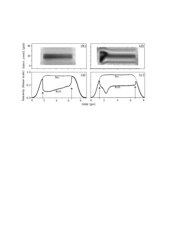
Fig. 13 (a) shows the incoherent switch-on of bright soliton, where the perpendicularly polarized switching pulse ( 10 ns) is applied at = 4 s. As apparent, a soliton forms after this incoherent light pulse. The slow formation of the soliton is apparent in Fig. 13 (a) (using roughly the time from = 4 to = 4.5 s).
It should be emphasized that this thermal effect is not instrumental for switching a soliton on. However, it allows switching a soliton off incoherently [30]. This is shown in Fig. 13 (b) where the driving light is initially raised to a level at which a soliton forms spontaneously (note again the slow soliton formation due to the thermal effect). The incoherent switching pulse is then applied which leads to disappearance of the soliton.

The soliton can thus be switched on and also off by an incoherent pulse. The reason for the latter is thermal. Initially the material is ”cold”. A switching pulse leads then to the creation of a soliton. Dissipation in the material raises the temperature and the soliton is slowly formed. At the raised temperature the band edge (and with it the bistability characteristic) and the existence range of solitons is shifted so that a new pulse brings the system out of the range of existence of solitons. Consequently the soliton is switched off.
Thus switching on a soliton is possible incoherently with the ”cold” material and switching off with the ”heated” material. When the driving intensity is chosen to be slightly below the spontaneous switching threshold the nonlinear resonator is cold. An incoherent pulse increases illumination locally and can switch the soliton on that causes local heating of the resonator. Another incoherent pulse aimed into the heated area can then switch the soliton off and thereby cool the resonator to its initial state, so that the soliton could be switched on/off again.
C Above bandgap bright solitons
At excitation above bandgap bright solitons form analogously to the below/near bandgap case [31]. Fig. 14 shows the bright solitons as observed in the reflected light with their characteristic concentric rings with the same appearance as the bright solitons below band gap (Fig. 9 (c)).
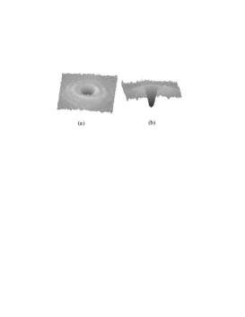
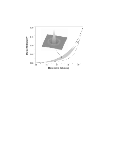
Fig. 12 compares the dynamics of the bright soliton formation for excitation above bandgap (left) and below bandgap (right). Difference between these two cases can be understood from the model. From (1) we obtain the reflected intensity as a function of incident intensity for wavelengths above (), as well as below the bandgap (), for plane waves (Fig. 15). One sees that the bistability range is large below and small above the bandgap. Solving (1) numerically the typical bright soliton (top of Fig. 15) is found coexisting with homogeneous intensity solutions in the shaded regions of Fig. 15 (a), (b).
After switching on the resonator below band gap (Fig. 15 (b)), the intensity in the resonator is high and with it the thermal dissipation. The temperature consequently rises, which shifts the band gap [29] and with it the bistability characteristic, so that the switch-off intensity, close to which the stable solitons exist, becomes close to the incident intensity. Then the resonator is in the basin of attraction for the solitons and the soliton forms as observed in Fig. 12 (c), (d).
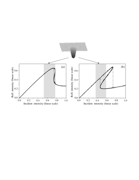
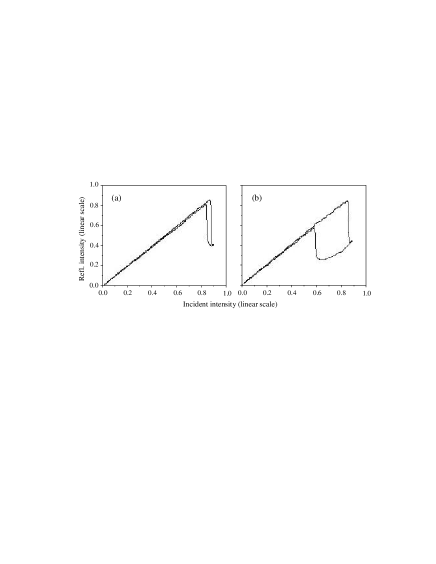
Above the band gap Fig. 12 (a), (b) show that the soliton is switched on ”immediately” without the slow thermal process. Fig. 15 (a) shows why. The plane wave characteristic of the resonator above band gap is either bistable but very narrow, or even monostable (due to the contribution of the self-focusing reactive nonlinearity [32]) but still with bistability between the soliton state (not plane wave) and the unswitched state. In this case the electronic switching leads directly into the basis of attraction for solitons and the switch-on of the soliton is purely electronic and fast. The width of the bistability characteristics observed experimentally (Fig. 16) scale in agreement with Fig. 15.
Nonetheless, also above bandgap there is strong dissipation after the switch-on. The associated temperature rise influences and can even destabilize the soliton. The effect can be seen in Fig. 12 (a). Over a time of a few s after the soliton switch-on the soliton weakens (reflectivity increases slowly) presumably by the rise of temperature and the associated shift of the band gap. At 6.5 s the soliton switches off although the illumination has not yet dropped.
Thus, while the dissipation does not hinder the fast switch-on of the soliton, it finally destabilizes the soliton. After the soliton is switched off, the material cools and the band gap shifts back so that the soliton could switch on again.
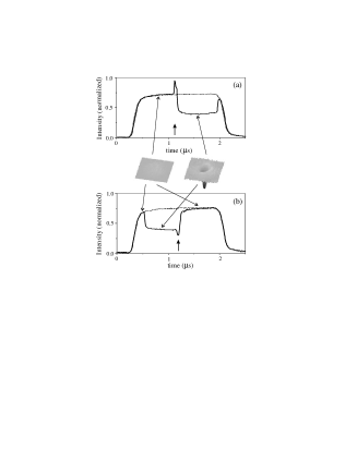
Fig. 17 shows the soliton coherent switching observations [33]. Fig. 17 (a) shows switching a soliton on. The driving light intensity is chosen slightly below the spontaneous switching threshold. At t 1.2 s the addressing pulse is applied. It is in phase with the driving light, as visible from the constructive interference. A bright soliton results, showing up in the intensity time trace as a strong reduction of the reflected intensity. Fig. 17 (b) shows switching a soliton off. The driving light is increased to a level where a soliton is formed spontaneously. The addressing pulse is then applied in counterphase to the driving light, as visible from the destructive interference. The soliton then disappears, showing up in the intensity time trace as reversion of the reflected intensity to the incident intensity value. The Fig. 17 insets show 2D snapshots before and after the switching pulses for clarity.
D Optical pumping
The thermal effects discussed above result from the local heating caused by the high intracavity intensity at the bright soliton location. They limit the switching speed of solitons and they will also limit the speed at which solitons could be moved around, limiting applications. The picture is that a soliton carries with it a temperature profile, so that the temperature becomes a dynamic and spatial variable influencing the soliton stability.
As opposed, a spatially uniform heating will not cause such problems, as it shifts parameters but does not constitute a variable in the system. The largely unwanted heating effects are directly proportional to the light intensity sustaining a soliton. For this reason and quite generally it is desirable to reduce the light intensities required for sustaining solitons.
Conceptually this can be expected if part of the power sustaining a resonator soliton could be provided incoherently to the driving field, e.g. by means of optical pumping. Optical pumping of MQW structure generates carriers and allows converting from absorption to gain. In the last case the semiconductor microresonator operates as VCSEL [17]. To couple pump light into the microresonator the pump laser was tuned in one of short-wavelength transparency windows in the reflection spectrum of the microresonator as shown in Fig. 2 (a).
When the pumping was below the transparency point and the driving laser wavelength was set near the semiconductor MQW structure band edge the bright and dark solitons formed (Fig. 18 (a), (b)) [34] similar to the unpumped case Figs 9, 10.
Analysis of (1) shows that increase of the pump intensity leads to shrinking of the resonator solitons’ existence domain and shifting towards low intensity of the light sustaining the solitons. Such reduction of the sustaining light intensity was observed experimentally in [23]. That is why soliton switchings in the pumped case are fast [23] and not mediated by thermal effects as for soliton formation without pumping (Fig. 12 (c), Fig. 13).
When the pump intensity approaches the transparency point of the semiconductor material, the resonator solitons’ domain of existence disappears. It reappears above the transparency point. In the experiment we have quite strong contribution of the imaginary part (absorption/gain) of the complex nonlinearity at the working wavelength (near band edge). Therefore the transparency point is very close to the lasing threshold so that inversion without lasing is difficult to realize.
Slightly above threshold we observe in presence of illumination structures (Fig. 19) reminiscent of the solitons in electrically pumped resonators [35]. We note that optical as opposed to electrical pumping allows more homogeneous pumping conditions [36]. This suggests that optically pumped resonators lend themselves more readily for localization and motion control of solitons then electrically pumped ones.
There is difference between below bandgap resonator solitons in pumped and unpumped cases. The nonlinear resonance mechanism of soliton formation [22] requires a defocusing nonlinearity below transparency (Fig. 3) and a focusing nonlinearity above transparency. Transverse nonlinear self-focusing effect is generally furthering soliton formation. Fig. 20 shows typical examples of calculated resonator solitons for pumped semiconductor microresonator. Bright solitons have a large existence range in the pumped case (Fig. 20), dark solitons exist, though with smaller range of stability, in the unpumped case (Fig. 3).
Thus optically pumped semiconductor resonators are well suited for sustaining solitons below bandgap: (i) background light intensity necessary to sustain and switch resonator solitons is substantially reduced by the pumping and therefore destabilizing thermal effects are minimized, (ii) above the transparency point only the dispersive part of semiconductor nonlinearity stabilizes a soliton, therefore the domain of existence of below bandgap (purely dispersive) bright solitons can be quite large.
V Conclusion
In conclusion, we have shown experimentally and numerically
existence of spatial solitons in driven semiconductor
microresonators over a wide spectral range around the bandgap:
below bandgap hexagons and dark solitons, near bandgap bright and
dark solitons, above bandgap bright solitons, optically pumped
below bandgap bright solitons. We have demonstrated the
manipulation of such solitons: switching them on and off by
coherent as well as incoherent light; reducing the light power
necessary to sustain and switch a soliton, by optical pumping.
Acknowledgment
This work was supported by Deutsche
Forschungsgemeinschaft under grant We743/12-1.
REFERENCES
- [1] D.W. Mc Laughlin, J.V. Moloney, A.C. Newell: Phys. Rev. Lett. 51, 75 (1983)
- [2] N.N. Rosanov, G.V. Khodova: Opt. Spectrosk. 65, 1375 (1988)
- [3] M. Tlidi, P. Mandel, R. Lefever: Phys. Rev. Lett. 73, 640 (1994)
- [4] G.S. Donald, W.J. Firth: J. Opt. Soc. Am. B 73, 1328 (1990)
- [5] M. Brambilla, L.A. Lugiato, M. Stefani: Europhys. Lett. 34, 109 (1996)
- [6] V.Yu Bazhenov, V.B. Taranenko, M.V. Vasnetsov: ‘Transverse optical effects in bistable active cavity with nonlinear absorber on bacteriorhodopsin’. In: Proc. SPIE, 1840, (1992) pp. 183-193
- [7] K. Staliunas, V.B. Taranenko, G. Slekys, R. Viselga, C.O. Weiss: Phys. Rev. A 57, 599 (1998)
- [8] G. Slekys, K. Staliunas, C.O. Weiss: Opt. Comm. 149, 113 (1998)
- [9] K. Staliunas, V.J. Sanchez-Morcillo: Phys. Rev. A 57, 1454 (1998)
- [10] V.B. Taranenko, K. Staliunas, C.O. Weiss: Phys. Rev. Lett. 81, 2236 (1998)
- [11] K. Staliunas: Phys. Rev. Lett. 81, 81 (1998)
- [12] C. Rebbi, G. Soliani: Solitons and Particles, (World Scientific, 1984)
- [13] C. Tamm: Phys. Phys. Rev. A 38, 5960 (1988)
- [14] K. Staliunas, C.O. Weiss, G. Slekys: ‘Optical vortices in lasers’. In: Optical Vortices. ed. by M. Vasnetsov and K. Staliunas (Nova Science Publishers, 1999) pp. 125-182
- [15] C.O. Weiss, M. Vaupel, K. Staliunas, G. Slekys, V.B. Taranenko: Appl. Phys. B 68, 151 (1999)
- [16] Soliton Driven Photonics, ed. by A.D. Boardman, A.P. Sukhorukov (Kluver Academic Publishers, 2001)
- [17] T.E. Sale: Vertical Cavity Surface Emitting Lasers, (Wiley, 1995)
- [18] H.M. Gibbs: Optical Bistability - Controlling Light with Light, (Academic Press, 1985)
- [19] L. Spinelli, G. Tissoni, M. Brambilla, F. Prati, L.A. Lugiato: Phys. Rev. A 58, 2542 (1998)
- [20] D. Michaelis, U. Peschel, F. Lederer: Phys. Rev. A 56, R3366 (1997)
- [21] L.A. Lugiato, R. Lefever: Phys. Rev. Lett. 58, 2209 (1987)
- [22] K. Staliunas, V.J. Sanchez-Morcillo: Opt. Comm. 139, 306 (1997)
- [23] V.B. Taranenko, C.O. Weiss, W. Stolz: Opt. Lett. 26, 1574 (2001)
- [24] V.B. Taranenko, I. Ganne, R. Kuszelewicz, C. O. Weiss: Phys. Rev. A 61, 063818 (2000)
- [25] P.K. Jacobsen, J.V. Moloney, A.C. Newell, R. Indik: Phys. Rev. A 45, 8129 (1992)
- [26] W.J. Firth, A.J. Scroggie: Europhys. Lett. 26, 521 (1994)
- [27] V.B. Taranenko, C.O. Weiss, B. Schäpers: Phys. Rev. A 65, 013812 (2002)
- [28] V.B. Taranenko, I. Ganne, R. Kuszelewicz, C.O. Weiss: Appl. Phys. B 72, 377 (2001)
- [29] T. Rossler, R.A. Indik, G.K. Harkness, J.V. Moloney, C.Z. Ning: Phys. Rev. A 58, 3279 (1998)
- [30] V.B. Taranenko, C.O. Weiss: Appl. Phys. B 72, 893 (2001)
- [31] V.B. Taranenko, C.O. Weiss, W. Stolz: J. Opt. Soc. Am. B 19, 8129 (1992)
- [32] S.H. Park, J.F. Morhange, A.D. Jeffery, R.A. Morgan, A. Chavez-Pirson, H.M. Gibbs, S.W. Koch, N. Peyghambarian, M. Derstine, A.C. Gossard, J.H. English, W. Weidmann: Appl. Phys. Lett. 52, 1201 (1988)
- [33] V.B. Taranenko, F.-J. Ahlers, K. Pierz: Appl. Phys. B (2002) in print
- [34] V.B. Taranenko, C.O. Weiss: ‘Spatial solitons in an optically pumped semiconductor microresonator’. nlin.PS/0204048 (2002)
- [35] Report as given in www.pianos-int.org
- [36] W.J. Alford, T.D. Raymond, A.A. Allerman: J. Opt. Soc. Am. B 19, 663 (1992)