The liquid Argon TPC: a powerful detector for future neutrino experiments and proton decay searches
Abstract
We discuss the possibility of new generation neutrino and astroparticle physics experiments exploiting the liquid Argon Time Projection Chamber (LAr TPC) technique, following a graded strategy that envisions applications with increasing detector masses (from 100 ton to 100 kton). The ICARUS R&D program has already demonstrated that the technology is mature with the test of the T600 detector at surface. Since 2003 we have been working with the conceptual design of a very large LAr TPC with a mass of 50-100 kton to be built by employing a monolithic technology based on the use of industrial, large volume, cryogenic tankers developed by the petro-chemical industry. Such a detector, if realized, would be an ideal match for a Super Beam, Beta Beam or Neutrino Factory, covering a broad physics program that includes the detection of atmospheric, solar and supernova neutrinos, and searches for proton decay, in addition to the rich accelerator neutrino physics program. A ”test module” with a mass of the order of 10 kton operated underground or at shallow depth would represent a necessary milestone towards the realization of the 100 kton detector, with an interesting physics program on its own. In parallel, physics is calling for a shorter scale application of the LAr TPC technique at the level of 100 ton mass, for low energy neutrino physics and for use as a near station setup in future long baseline neutrino facilities. We outline here the main physics objectives and the design of such a detector for operation in the upcoming T2K neutrino beam. We finally present the result of a series of R&D studies conducted with the aim of validating the design of the proposed detectors.
1 Introduction
The present generation of neutrino experiments will further clarify the scenario of neutrino mixing by reducing the errors on the oscillation parameters, by confirming the oscillation channel and by proving or disproving the existence of a fourth and sterile neutrino. This generation of experiments can be assumed to provide solid and convincing results by 2010. By then, in order to proceed along this fascinating line of research a new technological step will be required, both concerning the neutrino beam facilities (intensity and reliability) and the detectors (performance and mass). By that time the neutrino community will be confronted with the measurement of the (so far) unknown mixing angle. The relevance of this physics result is twofold: on the one hand, if this angle turns out to be non vanishing, the actual behavior of the three neutrino mixing scheme will be proved; on the other hand, the measurement of will open the way to the future searches for a possible CP violation in the leptonic sector. After one more decade one could assume that the latter research subject could be attacked by a further beam facility and detector generation, whose features can be hardly predicted today, apart from a generic request of unprecedented high beam intensity and huge detector mass.
Following the above (oversimplified) scenario, as far as detectors are concerned, it is clear that neutrino physics is now calling for new devices able to meet the challenge of the high intensity, and also capable of improved particle identification and background rejection performance. The large mass of these detectors and their complexity will obviously imply important financial investments. This will make mandatory an appropriate and economical use of these facilities, by extending their application to other fields, such as astroparticle physics and matter unstability searches. The realization of these detectors will also imply (actually, already by now) a vigorous and coordinated effort of the community on the required R&D activities, as well as a wise exploitation of existing resources and infrastructure, seeking for complementarity of the different worldwide projects.
We believe that the detection technique of the liquid Argon Time Projection Chambers is well suited to answer the demanding experimental requirements originating from the above considerations. In the last few years, in particular, we have been proposing a global research strategy centered on both the design and proposal of experiments exploiting this technique and on the related R&D strategy [1]. The main milestones of our line of thought can be summarized as follows:
-
•
after more than 20 years of R&D work from the ICARUS Collaboration all the basic elements of the LAr TPC technique have been successfully developed;
-
•
no ”black magic” is required to exploit the technique and realize detectors of increasing mass although specific research work might be needed for advanced applications;
-
•
we stress the importance of small laboratory prototype detectors to get acquainted with the technological issues and to study specific R&D subjects;
-
•
the next-to-come physics application might likely be the realization of a 100 ton detector for a LBL neutrino facility, able to study low energy neutrino interactions, to ascertain the capability of the technique in performing high precision neutrino physics experiments;
-
•
we have performed the conceptual design and preliminary engineering studies of a very large mass (50-100 kton) LAr TPC facility for ultimate proton decay searches and precision studies of the neutrino mixing matrix;
-
•
the above large mass facility, representing more than a factor 100 mass increase with respect to the ICARUS modular design approach, will require a two step strategy, possibly envisioning the realization of an ”engineering module” with a mass of the order of 1 kton (able to prove the scalability of the detector) and of a 10 kton detector able to provide a rich physics program and to justify the further factor of 10 mass increase for the very large facility;
-
•
a complete R&D program has been identified for several key issues. We already obtained interesting results and more projects are underway or planned for the next future.
After a brief introduction on the LAr detection technique, the above milestone are described in more detail in the next Sections together with the detector design features and experimental results from R&D studies.
2 The liquid Argon TPC technique
The Liquid Argon Time Projection Chamber was conceived and proposed by C. Rubbia in 1977 [2] as a tool for uniform and high accuracy imaging of massive detector volumes. The operating principle of the LAr TPC is based on the fact that in highly purified LAr ionization tracks could be transported undistorted by a uniform electric field over distances of the order of meters. Imaging is provided by wire planes placed at the end of the drift path, continuously sensing and recording the signals induced by the drifting electrons. Liquid Argon is an ideal medium since it provides high density, high ionization and scintillation yields, and is intrinsically safe and cheap.
Non-destructive readout of ionization electrons by charge induction allows to detect the signal of electrons crossing subsequent wire planes with different orientation. This provides several projective views of the same event, hence allowing for space point reconstruction and precise calorimetric measurement. The particle momentum can be inferred via a multiple scattering measurement, while the detection of the local energy deposition () can provide separation and particle identification through a range versus measurement. The total energy reconstruction of the event is performed by charge integration within the detector volume, being the detector a full-sampling, homogenous calorimeter.
The main technological challenges of this technology are summarized elsewhere [3] and included techniques of Argon purification, operation of wire chambers in cryogenic liquid and without charge amplification, low-noise analog electronics, continuous wave-form recording and digital signal processing. The extensive ICARUS R&D program dealt with studies on small LAr volumes, LAr purification methods, readout schemes and electronics, as well as studies with several prototypes of increasing mass on purification technology, collection and analysis of physics events, long duration tests and readout [4, 5, 6].
The realization of the 600 ton ICARUS detector (T600) culminated with the full test of one of the two 300 ton modules carried out at surface [3]. This test demonstrated that the LAr TPC technique can be operated at large mass scale with a drift length of 1.5 m. Data taking with cosmic-ray events allowed to assess the detector performance in a quantitative way [7, 8, 9, 10, 11]. Installation of the T600 module at the Gran Sasso Underground Laboratory is currently on-going.
Nowadays, LAr TPC detectors can be readily used in a broad energy range, from MeV up to multi-GeV with high event reconstruction efficiency. At the same time, low thresholds for particle identification are possible thanks to the high granularity. In addition to the natural use as underground facilities, one can also operate the detectors at shallow depth owing, once more, to the high granularity which permits the separation of signal from background. Finally, one can realistically think to embed a LAr TPC in a magnetic field for charge discrimination [12]. Implementations at different mass scales ( from 100 tons to 100 ktons) are therefore conceivable as well as technically and economically sound. In the following, we give some examples according to the global strategy outlined in the previous Section.
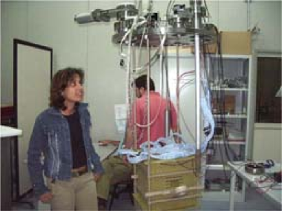
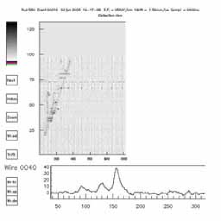
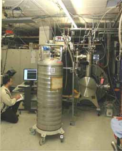
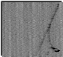
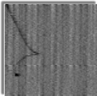
In parallel to the design of new experiments employing LAr TPC detectors, one could readily profit of the know-how acquired on the technique to setup small laboratory prototype detectors, able to permit the study of specific technological subjects and to gather the necessary expertise with all the related experimental issue. As an example, Fig. 1 shows a test chamber we have been operating at INFN Napoli, in particular for the study of UV laser-liquid Argon calibration [13]. The display of a cosmic-ray event taken with this detector is shown in Fig. 2.
3 A large mass liquid Argon TPC detector with charge imaging and light readout
A very large LAr TPC with a mass ranging from 50 to 100 kton would deliver extraordinary physics output, sometimes called “megaton physics”, owing to the excellent event reconstruction capabilities provided by the technique. Coupled to future Super Beams [14], Beta Beams or Neutrino Factories [12, 15] it could greatly improve our understanding of the mixing matrix in the lepton sector with the goal of measuring the CP-phase. At the same time, it would allow to conduct astroparticle experiments of unprecedented sensitivity.
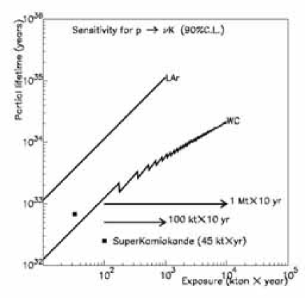
Let us mention, as an example, the physics reach of such a detector for nucleon decay searches. For the two prong decay mode: p + , a 100 kton LAr detector, thanks to its high detection efficiency ( 95%) and to the high background rejection power could effectively compete with a much larger mass (650 kton) water Cerenkov detector, reaching a sensitivity limit of years for a ten years run (Fig.3). This features strongly supports the concept of complementarity between the two detection methods for proton decay searches.
The basic features of the proposed detector [16, 1, 17, 18, 19] can be summarized as follows. The baseline design envisions a single 100 kton “boiling” cryogenic tanker at atmospheric pressure for a stable and safe equilibrium condition, since temperature is constant while Argon is boiling. The evaporation rate is small, less than of the total volume per day, and is compensated by refilling of the evaporated Argon volume. The detector signal is provided by charge imaging, scintillation and Cerenkov light readout, for a complete and redundant event reconstruction. A peculiar feature is represented by the fact that the detector is running in double-phase mode. In order to allow for drift lengths as long as 20 m, which provides an economical way to increase the volume of the detector with a constant number of channels, charge attenuation will occur along the drift due to attachment to the remnant impurities present in the LAr. This effect can be compensated with charge amplification near the anodes located in the gas phase.
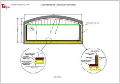
The cryogenics design of the proposed detector relies on the industrial know-how in the storage of liquefied natural gases (LNG), which developed in the last decades, driven by the petrochemical industry. The technical challenges associated to the design, construction and safe operation of large cryogenic tankers have already been addressed and engineering problems have been solved. The current state-of-the-art contemplates cryogenic tankers of 200000 m3. In the world presently exist 2000 tankers with volumes larger than 30000 m3, with the majority built during the last 40 years. Technodyne International Limited, UK [20], which has expertise in the design of LNG tankers, has produced for us a feasibility study in order to understand and clarify all the issues related to the operation of a large underground LAr detector.
The outcome of the collaboration with Technodyne is shown in Fig. 4 where the engineering design of the large detector is presented. The detector is characterized by the large fiducial volume of LAr included in a tanker with external dimensions of approximately 40 m in height and 70 m in diameter. A cathode located at the bottom of the inner tanker volume creates a drift electric field of the order of 1 kV/cm over a distance of about 20 m. In this field configuration ionization electrons are moving upwards while positive ions are going downward. The electric field is delimited on the sides of the tanker by a series of ring electrodes (race-tracks) placed at the appropriate potential by a voltage divider.
The tanker contains both liquid and gas Argon phases at equilibrium. Since purity is a concern for very long drifts of 20 m, we already mentioned that the inner detector could be operated in double-phase mode. In order to amplify the extracted charge one can consider various options: proportional amplification with thin readout wires, GEMs or LEMs (see Section 5). After a drift of 20 m at 1 kV/cm, the electron cloud diffusion reaches approximately a size of 3 mm, which corresponds to the envisaged readout pitch. If one assumes that the electron lifetime is at least 2 ms [10], one then expects an attenuation of a factor 150 over the distance of 20 m, compensated by the proportional gain at the anodes. We remind that the expected attenuation factor will not introduce any detection inefficiency, given the value of 6000 ionization electrons per millimeter produced along a minimum ionizing track in LAr. The number of readout channels is of the order of 100000 served by about 100 electronic crates placed on top of the tanker.
In addition to charge readout, one can envision to locate PMTs around the inner surface of the tanker. Scintillation and Cerenkov light can be readout essentially independently. LAr is a very good scintillator with a yield of about 50000 /MeV (at zero electric field). However, this light is distributed around a line at 128 nm and, therefore, a PMT wavelength shifter (WLS) coating is required. Cerenkov light from penetrating muon tracks has been successfully detected in a LAr TPC [9]; this much weaker radiation with about MeV produced between 160 nm and 600 nm for an ultra-relativistic muon can be separately identified with PMTs without WLS coating, since their efficiency for the DUV light will be very small. A total of 1000 8” PMTs would be required to readout the scintillation signal and about 27000 PMTs to cover 20% of the inner tanker surface to possibly detect the Cerenkov signal.
The operation of such a large facility is certainly challenging, although solutions exist for the main issues, such as cryogenics, provision of LAr, filling-up, purification, etc. [16, 1, 17, 18, 19]. Here we only stress that an ”in situ” plant producing liquid Argon might be an economical solution, also considering the cost of transporting the liquid from a distant production site. Assuming a filling speed of 150 ton/day (compatible with the daily production rate of such a plant) one would need about two years to fill the detector. Since the boiling-off of the tanker corresponds to 45 ton/day (for a 5 W/m2 heat input) it would take nearly 10 years to completely evaporate the whole detector volume.
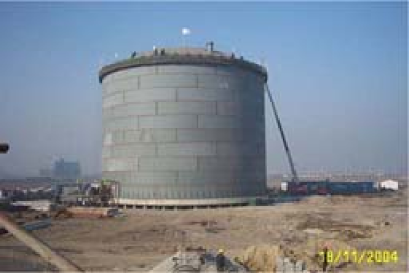
From the above design considerations, it is clear to us that the realization of a very large LAr TPC will require a graded program, likely implying the construction of a 1 kton engineering module to assess and implement the adopted technological and engineering solutions. At a later stage, one should aim at the realization of a 10 kton detector with a rich physics program on its own. Only after the successful meeting of these milestones, the following factor of 10 mass increase could be realistically afforded. This step-by-step procedure is justified both from the technological and the financial point of view. The 10 kton detector would feature a tanker with a diameter of 30 m and a height of 10 m, very similar to the LNG tanker shown in Fig. 5. The number of charge imaging channels will be about 30000.
A final remark on the detector cost. From our initial estimates the cost of a 100 kton (10 kton) detector built underground would be around 350 (80) million Euro.
4 A 100 ton LAr TPC for the T2K neutrino experiment
A 100 ton detector in a near site of a long baseline facility is a straightforward and very desirable application of the LAr TPC technique [21]. In particular, the approved T2K experiment in Japan [22] will provide the ideal conditions to study with high statistical accuracy neutrino interactions on liquid Argon in the very important energy range around 1 GeV. This is a mandatory step in order to be able to handle high statistics provided by the large detectors described in the previous Section. In addition, a smaller mass prototype of the 100 ton detector could offer a tool to study calorimetric (electromagnetic and hadronic) response in a charged particle beam or be readily placed in an existing neutrino beam.
The J-PARC to Kamioka neutrino project is a second generation long baseline neutrino oscillation experiment that will probe physics beyond the Standard Model by high precision measurements of neutrino mixing. A high intensity, off-axis, narrow band neutrino beam is produced by secondary pions created by a high intensity proton synchrotron at J-PARC. The neutrino energy is tuned to the oscillation maximum at 1 GeV for a baseline length of 295 km towards the Super-Kamiokande detector.
The project is divided into two phases. In the first, the main goal is the precision measurement of neutrino oscillation with the 50 GeV PS of 0.75 MW beam power and Super-Kamiokande as a far detector. The physics subject of the first phase is an order of magnitude better precision in the disappearance oscillation measurement, a factor of 20 more sensitive search in the appearance, and a confirmation of the oscillation or discovery of sterile neutrinos by detecting neutral current events. During the second phase, the power of the neutrino beam will be increased and a new far detector will be built [22].
In order to achieve the challenging goals of the T2K program, for the disappearance oscillation search one will need to precisely measure the and parameters with small systematic errors. For that, a very good knowledge of the neutrino beam will have to be reached. For the electron appearance experiment, in order to deeply understand the beam associated backgrounds, a very good knowledge of the intrinsic component of the beam and of the production in neutrino interactions in the GeV range will be mandatory. The above requirements are to be fulfilled by the use of a complex detector configuration. In fact, the T2K long-baseline program foresees two near detector stations, respectively at 140 and 280 m from the target, a third intermediate station at 2 km, and the far station represented by the existing Super-Kamiokande detector. The near detectors have to be built, and will be composed of different technologies, like in the case of the previous K2K experiment [23].
As far as the 2 km site is concerned, it is now planned to install a 1 kton water Cerenkov detector, a muon ranger and a so-called ”fine grain” detector constituted by a LAr TPC [21]. At the 2 km position, the rate in a 100 ton detector would be about 300000 events per year: this is a unique location for a liquid Argon TPC of such a mass. A list of physics measurements that could be performed in the T2K 2 km near station with a liquid Argon detector has been outlined in [1]. The merits of the detector for the T2K oscillation measurements combined to the other detectors of the 2 km site are discussed in detail in [21]. The main technological and detector issues of the 100 ton LAr TPC for T2K are reported in the following.
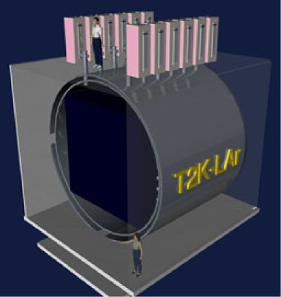
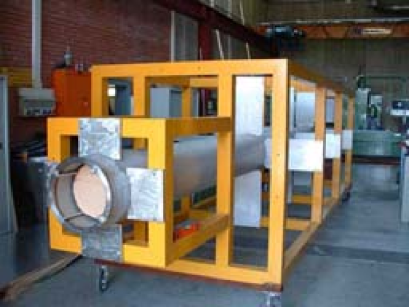
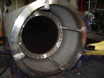
The LAr TPC for the T2K 2 km site is hosted in a 8.5 m long and 7.2 m diameter stainless steel dewar positioned on mechanical shock absorbers, as schematically shown in Fig. 6. Inside the outer dewar, an inner vessel of 5 m in length and 6.6 m in diameter contains the liquid Argon. The volume between the two vessels is evacuated and filled with super-insulation layers to ensure adequate thermal insulation. The outer cylinder acts as a thin skin for vacuum insulation. The heat input through these surfaces is estimated to about 100 W under high vacuum conditions. In case of loss of vacuum, the heat input increases to 4 kW. The inner vessel contains about 315 tons of liquid. A smaller volume of 150 tons is confined by the inner TPC, corresponding to a neutrino interaction fiducial volume of 100 tons. The basic concept for the liquid Argon cryostat has been developed and engineered following the internationally recognized codes for the design of conventional cryogenic-fluid pressure storage-vessels as covered in the ASME (American Standards of Mechanical Engineers) Boiler & Pressure Vessel Code, Sect. VIII.
The detector chamber consists of a stainless steel mechanical frame with parallelepiped shape inscribed in the inner vessel cylinder. The cathode of the TPC is placed in the middle of the inner volume along the longitudinal axis. There are two options for this element: either filled with frozen water or with solid CO2. The inner target is motivated by the fact that the extrapolation between Argon and water targets (2 km water Cerenkov and Super-Kamiokande) can be affected by uncertainties, which in turn would affect the goal of precision measurement of the oscillation parameters. The straightforward solution is, therefore, to insert an additional target within the 100 ton liquid Argon detector in ordere to collect a statistically significant event sample with interactions occurring in Oxygen (CO2 or H2O) and tracks reconstructed in LAr.
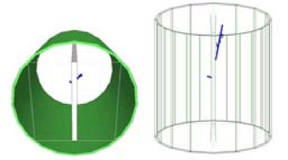
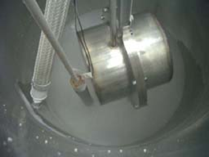
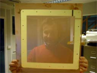
The first option for the inner target geometry is a cylindrical structure made of a 2 mm thick stainless steel cylinder of 60 cm diameter and 5 m length. The second option calls for a parallelepiped shaped target 25 cm thick and 5 m long (Fig. 7). In the latter case, two separate cathode planes would be placed onto the external sides of the target. For both options, the cathode electrode defines two half-volumes. We are conducting specific tests with prototype targets to study the freezing procedure of the target material. Fig. 8 shows one of these (cylindrical) prototypes during a laboratory test to simulate water target freezing inside a dewar being filled with liquid Argon.
Each of the two extreme sides of the half-volumes are equipped with two or three wire planes with different wire orientations, constituting the readout anodes. The electric field perpendicular to the wires is established in the LAr volume by means of a high voltage (HV) system. The system is composed of the above-mentioned cathode plane parallel to the wire planes, placed in the center of the cryostat volume at a distance of about 2 m from the wires of each side and defining the maximum drift length, and of field shaping electrodes made of stainless steel tubes. These are required to guarantee the uniformity of the field along the drift direction. At the nominal cathodic voltage of about 200 kV, corresponding to an electric field of 1 kV/cm, the maximum drift time in LAr is of about 1 ms. At this stage, two options are considered for polarization of the cathode and the corresponding electrodes. In the first option a HV feedthrough allows to set the required potential on the cathode. The electrodes are placed at degrading voltage from the cathode potential to ground via a series of resistors inserted between the tubes. In the second option, the use of a HV feedthrough is avoided if an oscillating low-voltage is multiplied inside the detector via a Greinacher circuit (see next Section).
Large area PMTs are placed inside the liquid, attached to the supporting mechanical structure, outside the inner fiducial volume and behind the wire planes. The PMTs are manufactured to be sensitive to the DUV prompt scintillation of Argon. These signals can be used for triggering on non beam associated events.
On top of the cryostat there are flanges equipped with cryogenic feedthroughs for the electrical connection of the wires with the readout electronics. These feedthroughs also provide passage for the internal instrumentation including PMTs, purity monitors, level meters, temperature probes, etc. The electronics allows for continuous readout, digitization and wave-form recording of the signals from each wire of the TPC. The frontend electronics is hosted in crates directly placed on top of the dewar.
The detector is complemented by ancillary cryogenics systems. A gas and liquid recirculation and purification system, a heat exchanger and a LAr buffer are placed in the underground cavern close to the detector dewar. These systems are connected through cryogenic pipes to the surface, where Argon storage, compressor, ventilation and evaporation systems complete the detector infrastructure.
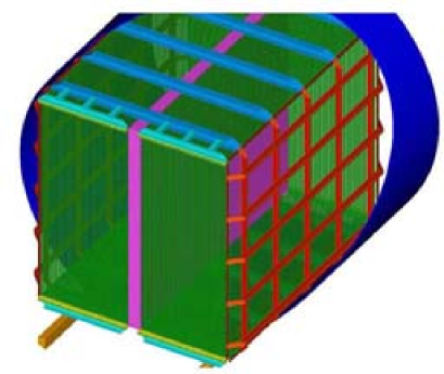
In more detail, the inner detector is composed of a rigid mechanical frame made of stainless-steel beams that is based on the cryostat floor by means of a system of rails and adjustable feet. The structure is made independent from possible deformations of the cryostat occurring during the initial cooling and it is also self-supporting. The stainless-steel frame has dimensions of about 5 m in length, 4.5 m in width and 4.5 m in height (Fig. 9). Two lateral wire-frames with the task of supporting the two (left and right) TPCs are positioned on the vertical longitudinal sides of the mechanical structure. The structure is designed in order to sustain the total force applied by the TPC wire tension without appreciable deformations. In the baseline option of two wire planes per each detector half this force amounts to about 9 ton. The structure is also designed to hold the signal and HV connectors, the PMTs, and the monitoring devices. Once assembled, the structure equipped with TPC planes and the other devices will be moved into the dewar by means of the bottom rails and subsequently aligned and placed in its nominal position.
As mentioned above, each TPC consists of a system of two parallel wire planes separated by 3 mm. The wire pitch normal to the wire direction is 3 mm. An additional third wire plane in each chamber would increase redundancy in the event reconstruction and help in solving possible ambiguities. Wires are made of AISI 304V stainless steel with a diameter of 150 m. They are stretched in the frame supported by the mechanical structure previously described. Each of the two-wire-plane chambers contain about 4500 wires, some of which decreasing in length. The tension applied to each wire corresponds to 10 N in the baseline option, although some optimization is expected following laboratory test we are presently conducting.
It is worth to stress a few points concerning the detector operation. Since no active refrigeration is foreseen, there are in total about 40 tons of steel to be cooled by liquid Argon boil-off during the initial cooling. The amount of Argon needed for this is about 20 LAr m3, less than 10% of the total stored Argon (315 ton). In normal operating conditions the total heat input induces a boil-off of about 200 l of liquid Argon per day, that is quite small. During forced liquid recirculation, required to yield high purity, the consumption is estimated to increase by additional 400 l/day. Since the cryostat is not actively cooled, with liquid N2, the cold input is externally provided either by compensation of the boil-off or preferably via a standard Linde-Hampson refrigeration process.
Refrigeration of the liquid Argon volume is performed by means of a closed circuit with a compressor placed at the surface, operated by a feed-back on the temperature and pressure of the inner vessel. Heat losses under normal operating conditions correspond to 500 W (cold) or 10 kW of electric power. If we include the power required for the liquid Argon recirculation/purification we reach a total of about 30 kW of electric power to be supplied.
The required LAr purity is firstly ensured by using suitable materials, cleaning, and careful design of the internal components. Additionally, internal surfaces can be vacuum conditioned, since during steady operation pollution of the LAr is mainly due to out-gassing of the inner surfaces and inner detector materials in contact with the gaseous Argon. The second requirement is that filling of the detector dewar from the external storage must be performed through sets of filters placed in series. Each set is dimensioned to allow for the purification of the LAr volume starting from standard commercial LAr (with a concentration of water and Oxygen of about 0.5 ppm). The third requirement is that a recirculation system has to be implemented in order to reach the ultimate purity of the liquid at equilibrium during detector operation, compensating for sources of impurities, typically degassing of materials immersed in the liquid. During the refrigeration cycle the gaseous Argon is passed through a purification filter before it is filled back as LAr to the inner vessel. Additional Argon purification is provided by a recirculation system through purification cartridges in liquid phase. A similar system turned out to be very important in the ICARUS T600 operation [10]. The liquid recirculation system can be dimensioned under the requirement of a 48 hours recirculation period. This implies a recirculation rate of about 3500 LAr l/hour (1 l/s). This can be handled by employing 7-8 filter cartridges arranged in two parallel circuits.
More details about the LAr TPC for T2K can be found in [21].
5 R&D towards a large mass liquid Argon TPC
Some studies are underway and others are planned with the aim of optimizing the design of future large mass LAr TPC detectors [17, 19]. We report here on the general R&D strategy and on results we have recently achieved.
The development of suitable charge extraction, amplification and collection devices is a crucial issue. We are continuing an R&D activity to further optimize the technique for charge extraction, amplification and collection, seeking a solution which yields gains between 100 and 1000 in pure Argon, that is electrically and mechanically stable, and easy to be mass produced. The starting point can be the Gas Electron Multiplier (GEM) detector developed by F. Sauli and coworkers [24]. It consists of a thin, metal-clad polymer foil, chemically pierced by a high density of holes. On application of a difference of potential between the two electrodes, electrons released by radiation in the gas on one side of the structure drift into the holes, multiply and transfer to a collection region.
A detector derived from the GEM on which we are presently conducting specific studies is the so called LEM (Large Electron Multiplier) [25]. It can be considered as a sort of macroscopic GEM built with a thick vetronite-Cu coated board (1-2 mm) with relatively large holes of 0.5 mm diameter. These features might make more easy the operation at cryogenic temperatures.
The LEM detector is shown in Fig. 10. In our preliminary measurements we have been studying the gain yield as a function of HV and gas pressure. Gains up to 800 seem to be achievable even at high pressure, with good prospects for operation in cold. A preliminary resolution of about 28% FWHM has been obtained for a Fe source. The experimental results agree with those expected from simulations.
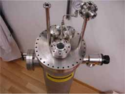
We are also conducting studies for the understanding of charge collection under high pressure as occurring for events occurring at the bottom of the large cryogenic tanker. At this purpose, we constructed a small chamber (Fig. 11) which will be pressurized to 3-4 bar to simulate the hydrostatic pressure at the bottom of a future 100 kton tanker. We plan to check that the drift properties of electrons are actually not affected at these pressure values.
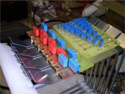
Another important subject of our current R&D studies is the problem of delivering very HV to the inner detectors, trying to avoid the use of (delicate) high voltage feedthroughs. We have realized a series of device prototypes based on the Greinacher or Cockroft-Walton circuit that allows to bring into the vessel a relatively low voltage and operate the required amplification directly inside the cryogenic liquid.
In preliminary tests with 20 amplification cells we have been able to reach about 40 kV. Nearly 2 kV/cm were obtained with the circuit successfully operating in liquid Nitrogen. A filter was built with two RC circuits in series in order to attenuate the ripple of the DC output by about 20 dB. The measurements indicate a very low noise level induced to the readout acquisition channels. However, in order to solve the problem of noise generation by the AC input signal of the HV circuit, some other solution can be envisaged. We foresee the use of an input signal at 50 Hz, a frequency very far from the bandwidth of any commercial preamplifier that can be used for the wire readout. A second possibility is to stop the AC signal when an event trigger is issued, as long as the full drift and acquisition time last. Further tests to reach 200 kV are ongoing and long term stability studies in cold are foreseen. Fig. 12 shows the implementation of one of the Greinacher circuits used for the test measurements. Fig. 13 illustrates the operation of the circuit immersed in liquid Nitrogen.
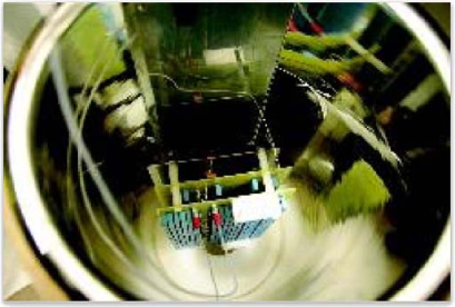
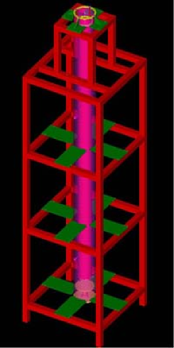
The realization of a 5 m long detector column will allow to experimentally prove the feasibility of detectors with long drift path and will represent a very important milestone in our global strategy. We have recently designed (Fig. 14) and completed the construction of a 6 m long and 40 cm in diameter dewar vessel housing a 5 m long prototype LAr detector (ARGONTUBE). The device will be operated with a reduced electric field value in order to simulate very long drift distances of up to 20 m. Charge attenuation and amplification will be studied in detail together with the adoption of possible novel technological solutions. We also plan to implement a high voltage system based on the previously described Greinacher approach. Fig. 15 shows the 5 m long TPC tube inserted in its supporting structure, while Fig. 16 depicts a detail of the inner detector tube inside the dewar vessel.
The study of LAr TPC prototypes in a magnetic field is an important breakthrough of the technique. Liquid Argon imaging provides very good tracking with measurement, and excellent calorimetric performance for contained showers. This allows for a very precise determination of the energy of the particles in an event, in particular for electron showers, which energy is very precisely measured. The possibility to complement these features with those provided by a magnetic field has been considered [12, 16] and would open new possibilities such as charge discrimination, momentum measurement of particles escaping the detector, and very precise kinematics, since the measurements are multiple scattering dominated ( for a track length of 12 m and a B field of 1T).
The orientation of the magnetic field is such that the bending is in the direction of the drift, where the best spatial resolution is achieved (in the ICARUS T600 a point resolution of was obtained). The magnetic field is hence perpendicular to the electric field. The Lorentz angle is expected to be very small in liquid. Embedding the volume of Argon into a magnetic field would therefore not alter the imaging properties of the detector and the measurement of the bending of charged hadrons or penetrating muons would allow a precise determination of the momentum and a determination of their charge. For muons, a field of 0.1 T allows to discriminate the charge for tracks longer than 4 m, corresponding to a momentum threshold of 800 MeV/c. Unlike muons or hadrons, the early showering of electrons makes their charge identification difficult. From simulations it is found that the determination of the charge of electrons of energy in the range between 1 and 5 GeV is feasible with good purity, provided that the field has a strength in the range of 1 T.
An R&D program to study the performance of a LAr TPC in a magnetic field was started in 2001. For this purpose, at ETHZ Zurich we have built a small liquid Argon TPC (width 300 mm, height 150 mm, drift length 150 mm) and placed it in the SINDRUM-I magnet kindly provided by the PSI Laboratory, producing field intensities up to 0.5 T (Fig. 17). The test program was conducted successfully and included checking the basic imaging, measuring traversing and stopping muons, testing charge discrimination, and checking of the Lorentz angle. The results have been recently published [26]. Two cosmic events collected with the device are shown in Fig. 18.
The further development of the industrial design of a large volume tanker able to operate underground will be also pursued in the framework of our future activities. The study initiated with Technodyne UK should be considered as a first “feasibility” study meant to select the main issues that will need to be further understood and to promptly identify possible “show-stoppers”. We expect to continue this study by more elaborated and detailed industrial design of the large underground (or shallow depth) tanker also including the details of the detector instrumentation. As anticipated, the cost of the full device will be estimated in more detail as well. At this preliminary stage a large mass LAr detector does appear to be a cost effective option.
Finally, we are investigating the study of logistics, infrastructure and safety issues related to underground sites. We are making investigations with two typical geographical configurations: a tunnel-access underground laboratory and a vertical mine-type-access underground laboratory. Early considerations show that such sites correspond to interesting complementary options. Concerning the provision of LAr, a dedicated, possibly not underground but nearby, air-liquefaction plant is foreseen. In collaboration with Technodyne we have started addressing the technical requirements and feasibility of such a facility.
6 Conclusions and outlook
The basic R&D work for the liquid Argon Time Projection Chamber technology has been successfully conducted by the ICARUS Collaboration, proving that it represents a mature particle detector technique with great potential for future neutrino and astroparticle physics experiments [3].
In the last few years we have outlined a global strategy for next generation experiments based on the use of this technique at different detector mass scales [1]. Our conceptual design of a 100 kton liquid Argon TPC seems technically sound; if realized, this detector would deliver extraordinary physics output and effectively complement giant 0.5-1 Megaton water Cerenkov detectors being proposed for future precision studies of the neutrino mixing matrix and for nucleon decay searches [27, 28]. Coupled to future Super Beams, Beta Beams or Neutrino Factories it could greatly improve our understanding of the mixing matrix in the lepton sector with the goal of measuring the leptonic CP-phase, and in parallel it would allow to conduct astroparticle experiments of unprecedented sensitivity.
The main design features of a large LAr TPC include the possibility of a double-phase operation with charge amplification for long drift distances, a charge imaging plus light readout for improved physics performance, and a very large boiling industrial cryostat (LNG technology). A full-scale, cost effective ”prototype” at the scale of 10 kton could be envisaged as an engineering design test with a physics program on its own. A first module with a mass of 1 kton could effectively play the role of a ”module zero” meant to assess the main technological issues of the design, its scalability to larger masses, and to verify the solutions adopted after the R&D studies conducted on specific subjects.
A 100 ton LAr TPC detector in a near-site of a long-baseline facility is a straightforward and desirable application of the technique [1]. The T2K experiment presently under construction in Japan will provide the ideal conditions to study with high statistical accuracy neutrino interactions on liquid Argon in the very important energy range around 1 GeV [22]. A proposed detector placed in the T2K 2 km site could provide the required reduction of the systematic errors for a high sensitivity measurement of the so far unknown mixing angle [21]. Also in this case, a smaller mass prototype would represent a useful tool to study calorimetric (electromagnetic and hadronic) response in a charged particle beam.
Work is in progress along the above lines of thoughts, with undergoing design and optimization studies, as well as with specific technical R&D activities. There is a high degree of interplay and a strong synergy between small and large mass scale apparatuses, the very large detector needing the small one in order to best exploit the measurements with high statistical precision that will be possible with a large mass.
In conclusions, we do believe that the liquid Argon TPC technique is one of the favorite detector approaches to meet the challenge of future experiments both on neutrino and on astroparticle physics. From past experience and undergoing studies one can be confident that the detector mass could actually scale from the 100 ton to the 100 kton mass range while keeping the basic outstanding features unaffected, and hence allowing for the design and the construction of cost effective and reliable devices, suitable for long term operation.
7 Acknowledgments
We kindly acknowledge the work of all the colleagues contributing to the data, to the experiments, and to the design and R&D activities presented in this paper. A.E. wishes to warmly thank F. Cervelli for the kind invitation to HIF05 and for the excellent organization of the workshop.
References
-
[1]
A. Ereditato and A. Rubbia,
”Ideas for future liquid Argon detectors”, Invited talk at the Third International Workshop on
Neutrino-Nucleus Interactions in the Few GeV Region, NUINT04, March 2004, LNGS,
Nucl. Phys. Proc. Suppl. 139 (2005) 301. -
[2]
C. Rubbia,
“The Liquid Argon Time projection Chamber: a new concept for Neutrino Detector”,
CERN-EP/77-08 (1977). -
[3]
S. Amerio et al.,
”Design, construction and tests of the ICARUS T600 detector”,
Nucl. Instum. Meth. A 527 (2004) 329 and references therein. -
[4]
P. Benetti et al.,
“A 3 ton Liquid Argon Time Projection Chamber”,
Nucl. Instrum. Meth. A 332 (1993) 395. -
[5]
P. Cennini et al.,
“Performance of a 3 ton Liquid Argon Time Projection Chamber”,
Nucl. Instrum. Meth. A 345 (1994) 230. -
[6]
F. Arneodo et al.,
“The ICARUS 50 l LAr TPC in the CERN neutrino beam”,
arXiv:hep-ex/9812006. -
[7]
S. Amoruso et al.,
“Measurement of the muon decay spectrum with the ICARUS liquid Argon TPC”,
Eur. Phys. J. C 33 (2004) 233. -
[8]
S. Amoruso et al.,
“Study of electron recombination in liquid argon with the ICARUS TPC”,
Nucl. Instrum. Meth. A 523 (2004) 275. -
[9]
M. Antonello et al.,
“Detection of Cerenkov light emission in liquid Argon”,
Nucl. Instrum. Meth. A 516 (2004) 348. -
[10]
S. Amoruso et al. ,
“Analysis of the liquid Argon purity in the ICARUS T600 TPC”,
Nucl. Instrum. Meth. A 516 (2004) 68. -
[11]
F. Arneodo et al.,
“Observation of long ionizing tracks with the ICARUS T600 first half-module”,
Nucl. Instrum. Meth. A 508 (2003) 287. -
[12]
A. Rubbia,
“Neutrino factories: detector concepts for studies of CP and T violation effects in neutrino oscillations”,
arXiv:hep-ph/0106088. - [13] C. Altucci et al., ”Realization and operation of a prototype liquid Argon Time Projection Chamber for studies on UV-laser monitoring”, in preparation.
-
[14]
A. Ferrari, A. Rubbia, C. Rubbia and P. Sala,
“Proton driver optimization for new generation neutrino Super Beams to search
for sub-leading oscillations ( angle)”,
New J. Phys. 4 (2002) 88. -
[15]
A. Bueno, M. Campanelli, S. Navas-Concha and A. Rubbia,
“On the energy and baseline optimization to study effects related to the
delta-phase (CP-/T-violation) in neutrino oscillations at a neutrino
factory”,
Nucl. Phys. B 631 (2002) 239. -
[16]
A. Rubbia,
“Experiments for CP-violation: A giant liquid argon scintillation, Cerenkov and charge imaging experiment?”,
arXiv:hep-ph/0402110. - [17] A. Ereditato and A. Rubbia, “Ideas for a next generation liquid Argon TPC detector for neutrino physics and nucleon decay searches”, Memorandum submitted to the CERN SPSC Villars session, April 2004, to appear in Proc. Workshop on Physics with a Multi-MW proton source, May 2004, CERN, Switzerland..
-
[18]
A. Rubbia,
“Very massive underground detectors for proton decay searches”,
arXiv:hep-ph/0407297. - [19] A. Ereditato and A. Rubbia, “Liquid Argon TPC: mid & long term strategy and on-going R&D”, to appear in Proc. of the International Conference on NF and Super Beam, NUFACT04, Osaka, Japan, July 2004.
- [20] Technodyne International Limited, Unit 16 Shakespeare Business Center, Hathaway Close, Eastleigh, Hampshire, SO50 4SR, see http://www.technodyne.co.uk
- [21] E. Kearns et al., ”A proposal for a detector 2 km away from the T2K neutrino source”, Document submitted to the US NUSAG Committee, 20 May 2005.
-
[22]
Y. Itow et al.,
“The JHF-Kamioka neutrino project”,
arXiv:hep-ex/0106019. -
[23]
M. H. Ahn et al.,
“Indications of neutrino oscillation in a 250-km long-baseline experiment”,
Phys. Rev. Lett. 90 (2003) 041801. -
[24]
F. Sauli, “GEM: a new concept for electron amplification in gas detectors”,
Nucl. Instrum. Meth. A 386 (1997) 531. -
[25]
P. Jeanneret, J. Busto, J. L. Vuilleumier, A. Geiser, V. Zacek, H. Keppner and R. de Oliveira,
“Performance of a new Micromegas detector, with woven wire mesh, in Cf-4”,
Nucl. Instrum. Meth. A 500 (2003) 133. -
[26]
A Badertscher, M. Laffranchi, A. Meregaglia and A. Rubbia,
”First operation of a liquid-argon TPC embedded in a magnetic field”,
New J. Phys. 7 (2005) 63. -
[27]
K. Nakamura, ”Hyper-Kamiokande: a next generation water Cherenkov detector”,
Int. J. Mod. Phys. A 18 (2003) 4053. -
[28]
M. Ishitsuka, T. Kajita, H. Minakata and H. Nunokawa,
”Resolving neutrino mass hierarchy and CP degeneracy by two identical detectors with different baselines”,
Phys. Rev. D 72 (2005) 033003.