Prototype for an Undulator-based Source for Polarised Positrons
Abstract
The full exploitation of the physics potential of a future Linear Collider requires the development of polarised positron beams. A very promising scheme for the technical realisation is the use of helical undulators, generating circular polarised photons of several MeV which are then converted in a thin target to longitudinally polarised positrons. The experiment E-166 tests this scheme. It uses the low-emittance 50-GeV electron beam at the Final Focus Test Beam (FFTB) at SLAC, passing through a 1 meter-long helical undulator. The flux and polarisation of the undulator photons as well as the properties of the positrons will be measured and will be compared with simulations.
pacs:
12.60.-iModels beyond the standard model and 13.88.+ePolarization in interactions and scattering and 29.27.HjPolarized Beams and 95.75.HiPolarimetry1 Introduction
Polarised electrons have been a part of the different Linear Collider proposals for a long time; the importance of beam polarisation in general was demonstrated at the SLAC Linear Collider (SLC), where during its last run 1997/98, an average longitudinal beam polarisation was reached.
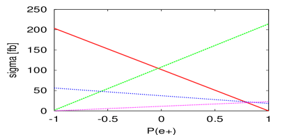
Recently much scrutiny has been given to the case for polarised positrons in addition to polarised electrons. Having both beams polarised leads to, e.g., the well–known effect of increasing the effective polarisation and reducing the relative error, see Hirose . Moreover, it is a very efficient tool for analysing non-standard couplings of new physics. E.g. SUSY transformations associate chiral (anti)fermions to scalars but . In order to prove this association the use of both beam polarised is necessary Bloechi ; e166 . As can be seen in Fig. 1, where the masses of the SUSY particles were chosen to be close together, GeV, GeV, the separation of both pairs , is only possible with both beam polarised. Even will not change the situation substantially. Another option when polarising both beams is the use of transversely polarised beams, where the cross section is then composed by: . The use of transversely polarised beams is an efficient tool for discovering, e.g., large extra dimension in and distinguishing different models Rizzo . The azimuthal asymmetry is symmetric in SM-like interactions. However, the exchange of the Graviton, Spin 2, particle leads to an asymmetric dependence, see Fig. 2. More examples can be found in pol-overview .
2 Technical layout of E-166
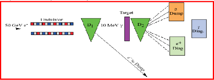
The SLAC experiment E-166 is a demonstration of undulator-based positron production for Linear Colliders (LC). It employs a helical undulator Balakin to generate photons of several MeV with circular polarisation which are then converted in a thin ( radiation length) target to generate longitudinally polarised positrons. The experiment will install a 1-meter-long, short-period ( mm, ), pulsed helical undulator in the Final Focus Test Beam (FFTB) at SLAC, see Fig. 3 e166 . A low-emittance 50-GeV electron beam passing through this undulator will generate circularly polarised photons with energies mainly up to the harmonic cutoff energy of about 10 MeV. These polarised photons are then converted in a radiation length Ti-alloy target to polarised positrons via pair production, see Fig. 3. As can be seen from Table 1, the photons produced in E-166 are in the same energy range and with the same polarisation characteristics as for a LC. Concerning the pair production process the same target thickness and material as in the LC are used, however, the positron intensity/pulse is lower by a factor 1/2000 compared to a positron source of a future LC.
2.1 Undulator design
The -rays are the result of backscattering of an electron beam of energy off the virtual photon of an undulator with period . To create positrons, -rays of at least a few MeV are needed. The intensity of the -rays depends on the intensity of the virtual photons, and hence on the square of its magnetic field strength, which is measured via the dimensionless undulator parameter . The undulator radiation is given by
and this photon number spectrum is rather flat up to the maximum energy of the first harmonic radiation
Since the highest practical beam energy at SLAC is 50 GeV, one chooses mm and .
The helical undulator is 1-m long, consists of a 0.6-mm-diameter copper wire bifilar helix, wound on a stainless-steel support tube, whose inner diameter is 0.889 mm. The on-axis field in the undulator is 0.76 T for a 2300-A excitation. The undulator is immersed in an oil bath for cooling.
2.2 Production of polarised positrons
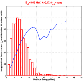
The polarisation state of the photon is transferred to the outgoing electron-positron pair in a thin target according to the cross section derived in Olsen . Positrons with an energy close to the energy of the incoming photons are 100% longitudinally polarised, while positrons with a lower energy have a lower polarisation. Due to an interplay between energy loss via bremsstrahlung followed by a slight loss of polarisation, the polarisation of positrons of a given energy is maximal in targets of up to 0.5 radiation length. In the E166 undulator design the positrons are generated at a 0.5 radiation-length-thick Titanium target, with a longitudinal polarisation and energy spectrum as shown in Fig. 4 (left). The composite polarisation of the total sample is about 53%.
2.3 Polarimetry at E-166
The measurement of the circular polarisation of energetic photons are based on the spin dependence of Compton scattering off atomic electrons. In E166 the transmission of unscattered photons through a thick magnetised iron absorber is used for the MeV -ray polarimetry polarimetry . The spin dependent part of the Compton scattering cross section is given by , where is the net polarisation of the photons, the net polarisation of the atomic electrons ( for iron saturation) and is the polarised Compton scattered cross section. The spin dependent part of the transmission probability is given by
where is the number density of atoms in iron and the length of the iron. It turns out that for about 7.5-MeV photons a 15-cm-thick magnetised iron absorber will become optimal, minimising the photon background radiation in the detector.
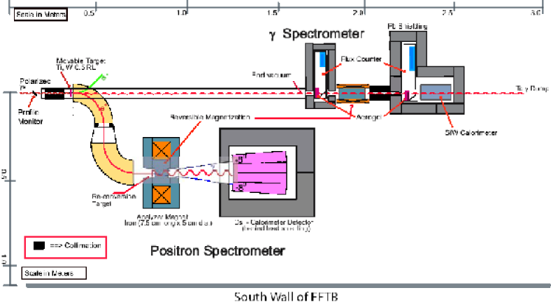
The photon polarimeter, see Fig. 4 (right) includes two types of detectors, a total absorption SiW calorimeter and an aerogel Cerenkov detector; the latter one is only sensitive to photons with an energy above 5 MeV and therefore independent of possible backgrounds of lower-energy photons.
The positron polarimeter consists of a 2-step process: the reconversion of the positrons at a 0.5-rad-length-thick Titanium target into polarised photons and the polarisation measurement (again via transmission polarimetry) of the obtained photons (typical energy of about MeV) with a CsI detector.
Geant simulations have shown that systematic errors of maximal up to are expected. This confirms that transmission polarimetry is well suited for E-166. More details about the technical layout of E-166 can be found in e166 .
2.4 Outlook
The project E-166 was approved in June 2003,
and will be scheduled for several weeks of running time in
January 2005 at the FFTB at SLAC.
The author would like to thank the organisers of the EPS2003 at Aachen for the wonderful and very interesting conference! GMP would like to thank all E-166 members for the interesting and constructive collaboration and the many, with great pleasure expected, weekly conference calls.
| Parameter | TESLA | NLC | E-166 |
|---|---|---|---|
| Beam Energy, [GeV] | 150-250 | 150 | 50 |
| /bunch | |||
| /pulse | 2820 | 190 | 1 |
| Pulses/s [Hz] | 5 | 120 | 30 |
| Undulator Type | plan./helical | helical | helical |
| Und. Parameter, | 1 | 1 | 0.17 |
| Und. Period, [cm] | 1.4 | 1.0 | 0.24 |
| Und. Length, [m] | 135 | 132 | 1 |
| Harmon., [MeV] | 9-25 | 11 | 9.6 |
| [/m/] | 1 | 2.6 | 0.37 |
| Target Material | Ti-alloy | Ti-alloy | Ti-alloy, |
| W | |||
| Target Thickn. [rad. len.] | 0.4 | 0.5 | 0.5 |
| Parameter | Units | Value |
|---|---|---|
| Length | m | 1.0 |
| Inner Diameter | mm | 0.89 |
| Period | mm | 2.4 |
| Field | kG | 7.6 |
| Undulator Parameter, K | – | 0.17 |
| Current | Amps | 2300 |
| Peak Voltage | Volts | 540 |
| Pulse Width | s | 30 |
| Inductance | H | 0.9 |
| Wire Type | – | Cu |
| Wire Diameter | mm | 0.6 |
| Resistance | ohms | 0.110 |
| Repetition Rate | Hz | 30 |
| Power Dissipation | W | 260 |
| /pulse | C | 2.7 |
References
- (1) T. Omori, A Polarized Positron Beam for Linear Colliders, KEK 98-237; T. Hirose et al., JLC, Nucl. Instr. and Meth. A455, 15 (2000).
- (2) C. Blochinger, H. Fraas, G. Moortgat-Pick, W. Porod, Eur. Phys. J. C 24 (2002) 297 [hep-ph/0201282].
- (3) G. Alexander et al, Undulator-Based Production of Polarized Positrons, SLAC-PROPOSAL-E-166, LC-DET-2003-044; http://www.slac.stanford.edu/exp/e166.
- (4) T.G. Rizzo, JHEP 0302, 008 (2003) [hep-ph/0211374].
- (5) G. Moortgat-Pick, H. M. Steiner, Eur. Phys. J. directC 3 (2001) 6 [hep-ph/0106155]; G. Moortgat-Pick, hep-ph/0303234; see also webpage of the polarisation working group ‘POWER’: http://www.ippp.dur.ac.uk/ gudrid/power.
- (6) V.E. Balakin, A.A. Mikhailichenko, The Conversion System for Obtaining High Polarized Electrons and Positrons, Budker Institute of nuclear Physics, Preprint BINP 79-85 (1979).
- (7) H. Olsen, L.C. Maximon, Phys. Rev. 114, 887 (1959).
- (8) H. Schopper, Nucl. Instr. and Meth. 3, 158 (1958); M. Fukuda, T. Aoki, K. Dobashi, T. Hirose, T. Iimura, Y. Kurihaya, T. Okugi, T. Omori, I. Sakai, J. Urakawa, M. Washio, Phys. Rev. Lett. 91 (2003).