Measuring the initial electron beam polarization in e collisions 111Adapted from the talk given in Chicago LC Workshop, 2002
Abstract
The investigation of process is crucial for a possible high energy or collider since it offers the possibility for both new physics discovery and precision measurements. The polarization of the initial beam is a limiting factor for the systematic errors in both cases. This note addresses the feasibility of making a measurement of the initial electron beam polarization with relative statistical error of one percent. Generator and detector level MC tools are used to obtain a realistic event selection for the signal process at the future CLIC test facility running at GeV.
1 Introduction
The next high energy colliders [1] or their precessor test facilities will also be capable of achieving highly polarized and collisions at high luminosities due to recent advencements in laser technology [2]. In the collisions which can uniquely be identified due to the net (-1) charge in the final state, one of the very interesting processes is
| (1) |
Depending on the center of mass energy (), the luminosity () of the collider and the polarization () of the beams, this process can be used to investigate
The initial
electron beam polarization will contribute to the systematic error on any
measurement and will thus be a limiting factor on the total error.
This note, thefore, focuses on the measurement of the initial electron beam
polarization with a small relative error of about 1 percent.
After putting down the requirements on the polarization measurement,
the properties of the “signal” process and the source for the direct background
events will be presented. The second section summarizes the Monte Carlo
tools used during this study. The results for event selection efficiency and
background rejection will be shown for different final states in section three.
Finally, in the proposed CLIC1 [5] accelerator, some time estimates
for the intended electron polarization measurement are presented using
different decay channels.
Since CLIC1 will solely be an electron accelerator, the positron channel
is not considered in this work.
The lowest order Feynman diagrams that would yield a final state are shown in Figure (1). In the Standard Model, with massless neutrinos, the helicity of the incoming is fixed by the , implying zero contribution to the total cross section () from a the right handed electrons (). Therefore the channel diagram can even be turned off by choosing 100 % opposite and polarizations. This concept will be the key point to measure beam polarizations. The surviving channel diagram is of particular interest since, the trilinear gauge boson coupling allows testing, among other things, the V-A structure of the standard model [6], extra charged gauge bosons [7].
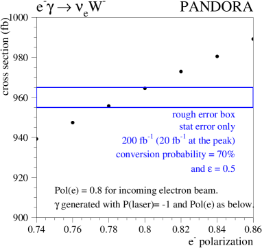
If one assumes a fixed laser photon beam polarization, the change in the total cross section of the signal events due to the change in electron beam polarization is given in Figure 2. We note that in order to determine the electron polarization with an error of 1.0 %, one has to measure the cross section with an accuracy of 5 permille. For the estimation of the required data taking time for such a measurement, only statistical errors and direct backgrounds will be considered. The contributions from the misidentifications and systematic errors are detector dependent and are not included in this note.
Naturally, the final state will be identified through ’s decay products. The possible tree level background to the final states will arise from the photon structure [8] and invisible decays. Figure 3 shows these background diagrams coming from the leptonic and hadronic structure of the photon for the non-electron channels. The Figure 4 shows the background diagrams for the electron final states including the additional backgrounds from the the invisible decays of .
2 MC tools and Backgrounds
As event generators, two different programs are used:
- Pandora V2.21
- CompHEP V41.10
The beamline parameters can be tuned in both generators for realistic beamstrahlung estimation. For the computations in this note, the proposed CLIC Higgs Experiment’s parameters (based on CLIC1) are used [5]: Bunch size (x+y)=157nm, Bunch length=0.03mm, Ne/bunch= . The photon spectrum in both generators is pure laser spectrum, without the Williams Weizsacker [14] contribution. For Pandora, the laser is assumed to be 100 % polarized.
A Higgs particle of mass about 120GeV [15], requires the optimization of the photon beams in the intented CLIC1 machine with ee of 150 GeV. The parameter , commonly known as Telnov’s , becomes different than the conventional value of 4.83. The maximum photon beam energy is then given with the formula:
| (2) |
To get a converging value of the effective cross section a minimum set of cuts are applied at the generator level. These are:
P 5 GeV
E GeV,
.
The total effective cross sections obtained from both generators are:
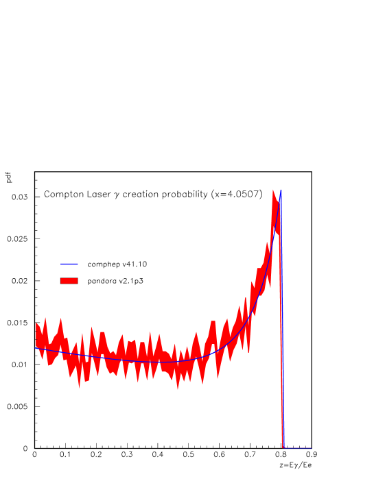
The difference in the cross sections is understandable in light of the slight difference in the peak position of the Laser backscattered photon spectra of Figure 5. After fragmentation, both generators give output files in StdHEP format which are then sent to a fast simulation program of a NLC type detector. For this analysis the ”small detector” is selected. The description of the fast MC package and the properties of available detector descriptions can be found elsewhere [16].
The simulations presented in this note are solely from CompHEP, since Pandora can’t be used to compute the backgrounds. CompHEP has only unpolarized beams. Nevertheless for the signal process, the case of 100 % opposite electron and photon helicities can be simulated by artificially turning off the channel in Figure 1 .
3 Event selections
To find the appropriate cuts for each channel, about 10,000 signal and 10,000 background events are created and processed in the fast detector simulation [17]. For each channel, the cuts and their values are found by optimizing the statistical significance .
3.1 Lepton channels
| channel | (fb) | (fb) |
|---|---|---|
| , () | 276.0 1.24 | 35.68 0.08 |
| , () | 276.1 1.65 | 36.44 0.09 |
| , () | 276.8 1.9 | 1116 4 |
In Table 1, signal and background effective cross sections are given for leptonic decays of , for of 150 GeV. For identification , the required signature is a charged lepton () + . So far only muon and electron channels are investigated. For both cases the identification is assumed to be 100 % efficient.
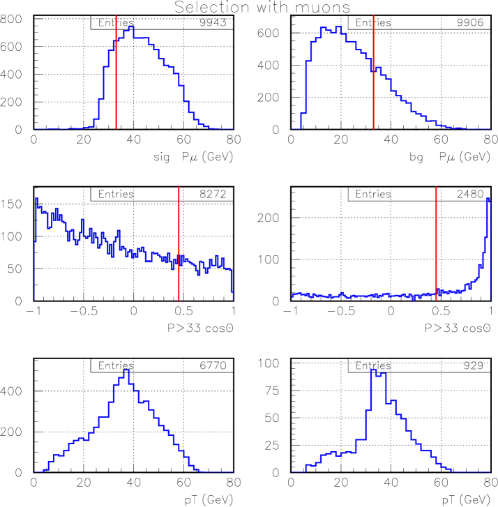
Figure 6 has the distributions of selected kinematic quantities for signal (left) and background (right) muons. The red vertical lines in the top four plots represent the optimized cut values. The bottom two plots are the transverse momentum distributions of the remaining signal and background events. The muons from the resolved photon are soft and along the photon’s momentum. These two properties allow a reduction on the background of about 91 % for a signal loss of about 32 %. For the muon channel, the used cuts and their efficiencies are given in Table 2. The results of the similar studies for the electron channel are presented in Table 3.
| signal | background | |
|---|---|---|
| applied cut | loss (%) | reduction (%) |
| No Jets, 1 Lepton | ||
| P GeV | 17 | 75 |
| cos() | 15 | 16 |
| signal | background | |
| applied cut | loss (%) | reduction (%) |
| No Jets, 1 Lepton | ||
| P GeV | 42 | 99 |
3.2 Hadron channels
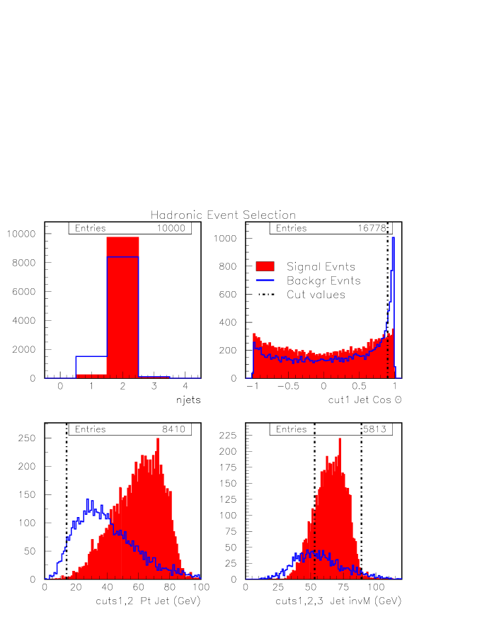
Final states containing and are the major contributors for both the signal & background cross sections. The contribution from quark is practically null due to smallness of Vcb and Vub. The jets are reconstructed with DURHAM algorithm, with a typical rapidity cut, , of 0.04 . The required signature is a two jet event (2j) + . Figure 7 contains distibutions for selected quantities for the signal in shaded red and in blue for the backgrounds. The black vertical lines are the optimized cut values. The main property of the background jets is to follow the photon direction with small transverse momenta. In each plot the additive effect of the selected cuts are shown. The optimized value for each cut and the cumulative efficiencies are presented in Table 4. With these cuts, about 90 % of the background can be eliminated with a signal loss of about 50 %. These ratios will be assumed to hold for the other hadronic channels as well.
| signal | background | |
| applied cut | loss | reduction |
| 2 Jets only events | 2.6 % | 7.4 % |
| Cos() both jets | 16 % | 45 % |
| Pt GeV | 39 % | 80 % |
| 53 M GeV | 49 % | 90.4 % |
4 Conclusions
After the cuts, the effective cross section for the signal and background
events in the muon and electron channels is given in Table 5.
The error on the cross section is calculated with the number of events after
background subraction, assuming a Snowmass year of seconds.
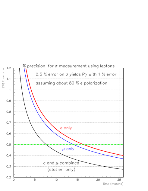
The decrease of the statistical error in the signal cross section as a
function of data taking time is shown in Figure 8
for electron and muon channels both separetely and combined.
If the events from two channels are combined,
a measurement of with 1 % statistical error can be obtained in
less than a year of nominal operation with the Snowmass efficiency of about
30 percent.
| signal | background | signal | Z bg | bg | ||
| 188.0 | 3.4 | 161.2 | 9.4 | 4.6 |
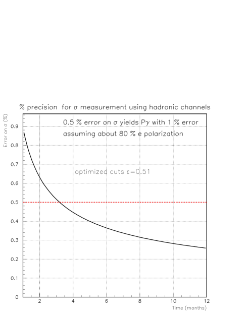
For the hadronic final states, only one main channel was considered to find the optimal cuts. The obtained signal survival probability is then extented to all hadron channels to compute the total number of events necessary to make a precision measurement on the cross section. The effective cross sections of the signal and background processes after the applied cuts are presented in table 6 . The results of a precision measurement on the cross section to obtain the polarization is presented in Figure 9. We see that if the hadron channel can be used, the polarizarion of the initial electron beam can be obtained with a one percent statistical error can be obtained in about 3-4 months.
| signal | background | |
|---|---|---|
| 837 | 28 |
For this study we only have considered the statistical errors and the direct backgrounds. The study of misidentifications and fakes is not yet considered. Nevertheless, it is shown that the inial electon beam polarization is measureable with a good precision using the process.
Acknowledgements: The author is grateful to M. Velasco and M. Schmitt for introduction to the subject and to M. Karagoz Unel for fruitful discussions.
References
-
[1]
“Next Linear Collider (NLC) test accelerator:
Conceptual design report”, SLAC-0411, Aug 1993. 121pp.
“The CLIC Test Facility - CTF2: A Two beam test accelerator for linear collider studies ”, CERN-PS-96-14-LP, Jun 1996. 40pp.
“TESLA linear collider: Status report ”, LCWS 2000, Oct 2000. -
[2]
T.W. Markiewicz and F. Pilat, Snowmass 2001 -Interaction Regions,Working group summary.,
J.Early, talk given at Linear Collider Workshop 2000,
R. Beach, talk given at NLC Workshop 2000, http://www-project.slac.stanford.edu/lc/local/Reviews/Oct2000Rev/Injector Sys/RBeachMLaserSysLLNL.pdf -
[3]
E.M. Gregores, M.C. Gonzalez-Garcia, S.F. Novaes, Phys.Rev. D56 (1997) 2920-2927
O. J. P. Eboli, J. K. Mizukoshi, Phys.Rev. D64 (2001) 075011 -
[4]
O.J.P. Eboli et al, Phys.Lett. B311 (1993) 147-152
J.E. Cieza Montalvo, O.J.P. Eboli Phys.Rev. D47 (1993) 837-843 - [5] D. Asner, et al, hep-ex/0111056, submitted to Eur. Phys. Jour.
- [6] DELPHI Collaboration, Phys.Lett. B502 (2001) 9-23
- [7] S. Godfrey et. al., Phys.Rev. D63 (2001) 053005
- [8] L. Jonsson, ”Real and Virtual Photon Structure”, Proceedings ’QCD and High Energy Hadronic Interactions’, Recontres de Moriond, hep-ph/0207181.
- [9] M.E. Peskin, Talk given at 1999 International Workshop on Linear Colliders, hep-ph/9910519
- [10] T. Sjostrand, ep-ph/9508391
- [11] T. Abe, M. Iwasaki, Talk given at Snowmass 2001, hep-ex/0110068
- [12] A.Pukhov et al, hep-ph/9908288
- [13] A.S.Belyaev et al, Talk given at 7th International Workshop on Advanced Computing and Analysis Technics in Physics Research, (ACAT2000, Fermilab, October 16-20, 2000), hep-ph/0101232
-
[14]
C. Weizsaker, Z. Phys. 88, 612 (1934),
E.J. Williams, Phys. Rev. 45, 729 (1934) - [15] L3 Collaboration, Phys.Lett. B517 (2001) 319-331
- [16] M. Iwasaki, T. Abe, Talk given at 5th International Linear Collider Workshop (LCWS2000), hep-ex/0102015
- [17] M. Iwasaki, Talk given at 4th International Linear Collider Workshop (LCWS1999), hep-ex/9910065