The QCDOC supercomputer: hardware, software, and performance
Abstract
An overview is given of the QCDOC architecture, a massively parallel and highly scalable computer optimized for lattice QCD using system-on-a-chip technology. The heart of a single node is the PowerPC-based QCDOC ASIC, developed in collaboration with IBM Research, with a peak speed of 1 GFlop/s. The nodes communicate via high-speed serial links in a 6-dimensional mesh with nearest-neighbor connections. We find that highly optimized four-dimensional QCD code obtains over 50% efficiency in cycle accurate simulations of QCDOC, even for problems of fixed computational difficulty run on tens of thousands of nodes. We also provide an overview of the QCDOC operating system, which manages and runs QCDOC applications on partitions of variable dimensionality. Finally, the SciDAC activity for QCDOC and the message-passing interface QMP specified as a part of the SciDAC effort are discussed for QCDOC. We explain how to make optimal use of QMP routines on QCDOC in conjunction with existing C and C++ lattice QCD codes, including the publicly available MILC codes.
I Introduction
Lattice QCD directly performs the path integral for the QCD Lagrangian by Monte-Carlo integration on a computer. Space-time is discretised on a 4-torus, and a large number of snapshots of typical vacuum configurations is used to evaluate hadronic correlation functions non-perturbatively. The numerical integration scheme introduces finite-volume, discretisation, and statistical errors that can be removed with sufficient compute power: lattice QCD is systematically improvable.
With improved actions and extrapolation in the lattice spacing, fairly modest lattice sizes, such as , are believed to be adequate for controlling the discretisation and finite volume effects on most hadronic observables.
Algorithms for including the effects of quark loops in the selection of typical vacuum configurations are numerically very expensive. The expense is believed to grow with a large power of the inverse quark mass for current best algorithms, and has thus far not been paid in full by lattice simulations, either choosing to ignore such effects (quenching) or simulating with artificially large quark masses. The goal for lattice QCD is to simulate in a region where the dynamical quark mass at least reliably connects to chiral perturbation theory, if not to the physical masses, and requires at least many tens of Teraflop years of computer power.
The notable characteristic of this problem is the need to focus ever more compute power on reducing the quark mass for a fixed problem size, rather than scaling up the problem size as more compute power becomes available. To this end QCDOC has been designed to allow efficient distribution of a single lattice QCD simulation over a very large multi-dimensional grid of a few tens of thousands of compute nodes.
At such extreme scalability the sparse matrix inversions involved require both global summation and nearest neighbour communication at a much shorter timescale than on smaller MPPs. Consequently both global summation time and nearest neighbour latency bite much harder, and both the QCDOC hardware and software have been designed to address these issues very effectively, with an order of magnitude improvement over traditional cluster technology on these key operations.
II QCDOC hardware
II.1 Overview
Continuing advances in the microelectronics industry have made it possible to integrate almost all components that make up a computer system on a single chip. This is known as system-on-a-chip technology. Using this technology, the individual processing nodes in a massively parallel computer can be greatly simplified. This is the idea behind the design of the QCDOC supercomputer: the processing elements consist of a single application-specific integrated circuit (ASIC) and an industry-standard DDR memory module. Large machines can then be build by simply adding many such processing elements.
The main ingredients of the QCDOC ASIC are
-
•
500 MHz, 32-bit PowerPC 440 processor core
-
•
64-bit, 1 GFlops floating-point unit
-
•
4 MBytes of on-chip memory (embedded DRAM)
-
•
controllers for embedded and external memory
-
•
nearest-neighbor serial communications unit with aggregate bandwidth of 12 Gbit/s in 12 independent directions
-
•
other components such as Ethernet controller, interrupt controller, etc.
In the following subsections, the QCDOC hardware is described in more detail (see also Ref. lat01 ). The main advantages of the QCDOC design are
-
•
high scalability: 50% sustained performance for typical applications on machines with several 10,000 nodes
-
•
low price-performance ratio of $1 per sustained MFlops
-
•
low power consumption
-
•
high reliability
II.2 The QCDOC ASIC
IBM is the leading vendor in the system-on-a-chip industry. The QCDOC ASIC was designed in close collaboration with IBM Research (Yorktown Heights) and is shown schematically in Fig. 1.
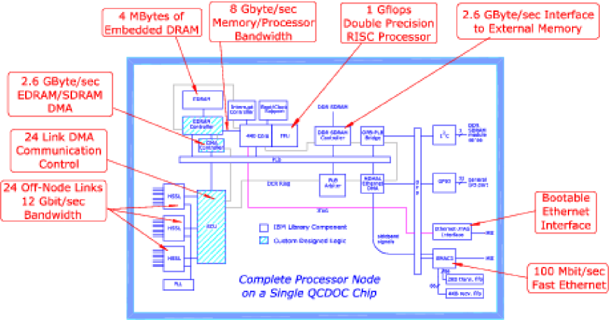
It contains standard cores from the IBM library as well as custom-designed components for faster memory access and high-speed off-chip communication.
The on-chip components are linked by three busses from IBM’s CoreConnectTM technology PLB :
-
•
Processor local bus (PLB). This is a 128-bit wide, fully synchronous bus running at 1/3 of the CPU frequency. It contains independent read and write data busses. The PLB protocol (implemented by the PLB arbiter) is rather sophisticated, allowing for pipelining, split transactions, burst transfers (fixed and variable length, early termination possible), DMA transfers, programmable arbitration, and other features such as timeout, abort, etc.
-
•
On-chip Peripheral Bus (OPB). This is a 32-bit wide, fully synchronous bus running at 1/6 of the CPU frequency. Its basic purpose is to off-load slower devices from the PLB bus.
-
•
Device Control Register Bus (DCR). This is a very simple bus which is used to read and write various control registers in the on-chip devices. The 440 is the only master on this bus.
The IBM library components in the ASIC are
-
•
The PowerPC-based 440 CPU core 440 with attached 64-bit IEEE floating point unit FPU . The 440 is a Book E compliant 32-bit processor with a 32 kByte prefetching instruction cache and a 32 kByte data cache with flexible cache control options (64-way associative, partitionable, lockable). The processor includes memory management with a 64-entry translation-lookaside-buffer which supports variable page sizes from 1 kByte to 256 MByte. It also features dynamic branch prediction and a 7-stage, dual issue pipeline. The target frequency of the 440 is 500 MHz, i.e. the peak performance is 1 GFlops.
The 440 also features a JTAG interface. JTAG (Joint Test Action Group) is an industry-standard protocol that allows an external device to take complete control of the processor. This functionality will be used for booting and debugging, see below. -
•
4 Mbytes of embedded DRAM (or EDRAM) which is accessed with low latency and high bandwidth through a custom-designed controller, the PEC, see below.
-
•
The PLB arbiter provides programmable arbitration for the up to eight allowed masters that can control PLB transfers. We are using six masters: the 440 instruction read, data read, and data write interfaces (the last two are channeled through the PEC), the EDRAM DMA, the SCU DMA, and the MAL DMA used by the Ethernet controller.
-
•
The PLB-OPB bridge is used to transfer data between the two busses. It is the only master on the OPB and a slave on the PLB.
-
•
The Universal Interrupt Controller (UIC) processes the interrupts that are generated on- and off-chip and provides critical and non-critical interrupt signals to the 440.
-
•
The DDR controller is a slave on the PLB, capable of transferring data to/from external DDR (double data rate) SDRAM at a peak bandwidth of 2.6 GBytes/s. It supports an address space of 2 GBytes and provides error detection, error correction, and refresh of the off-chip SDRAM.
-
•
The Ethernet media access controller (EMAC) provides a 100 Mbit/s Ethernet interface (it also supports Gbit-Ethernet, but we are not making use of this capability). The media-independent interface (MII) signals at the ASIC boundary are connected to a physical layer chip on the daughterboard. The EMAC is a slave on the OPB and has sideband signals to the MCMAL on the PLB.
-
•
The DMA-capable Memory Access Layer (MCMAL) loads/unloads the EMAC through the sideband signals. It is a master on the PLB.
-
•
The inter-integrated circuit (I2C) controller is a slave on the OPB. It is used to communicate with off-chip devices supporting the I2C protocol, such as the serial presence detect EPROM on the DDR DIMM or voltage and temperature sensors on the motherboard.
-
•
The general purpose I/O (GPIO) unit is another slave on the OPB whose 32-bit wide data bus is taken out to the ASIC boundary. It is used, e.g., to drive LEDs, to control the global interrupt tree, and to receive interrupts from off-chip devices.
-
•
The high-speed serial links (HSSL) used by the SCU each contain eight independent ports (four each for send/receive) through which bits are clocked into/out of the ASIC at 500 Mbit/s per port. The bits are converted to bytes (or vice versa) in the HSSL. The HSSL input clocks are phase-aligned by another IBM macro, the phase-locked loop (PLL).
In addition to the components provided by IBM, the QCDOC ASIC contains custom-designed components. Most importantly, these components provide essential support for the high-speed communications required in a massively parallel machine.
-
•
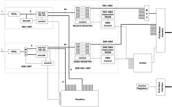
Serial Communications Unit (SCU). The task of the SCU is to reliably manage the exchange of data between neighboring nodes with minimum latency and maximum bandwidth. The design takes into account the particular communication requirements of lattice QCD simulations. A schematic picture of the SCU is shown in Fig. 2.
The custom protocol governing the data transfers defines packets that contain a 64-bit data word and an 8-bit header containing control and parity bits. When the receive unit receives a packet, it first interprets the header, buffers the bytes from the HSSL, and assembles the 64-bit word. It then transfers the word to the receive register or passes it on to the send unit. The receive buffer can store three 64-bit words so that the send unit (in a neighboring node) can send three words before an acknowledgment is received. The functionality of the send unit is essentially the inverse of that of the receive unit. Send and receive operations can proceed simultaneously. Each send or receive unit is controlled by a DMA engine which then transfers the data between memory and a send/receive register. Each DMA engine is controlled by block-strided-move instructions stored in SRAM in the SCU itself.
A low-latency passthrough mode is provided for global operations. Because of the latencies associated with the HSSL, the most efficient method to perform global sums is “shift-and-add”, using a store-and-forward capability built into the SCU. The main advantage of this scheme is that the software latency of about 300 ns is paid only once per dimension, rather than for each node in this dimension.
The total end-to-end latency is estimated to be about 350 ns for supervisor transfers and about 550 ns for normal transfers. This is at least an order of magnitude lower than the latency associated with Myrinet. Since a write instruction from the 440 can initiate many independent transfers on any subset of the 24 send or receive channels, the latencies associated with multiple transfers can be overlapped to some degree. The total off-chip bandwidth using all 24 HSSL ports is 12 Gbit/s. In a 4-dimensional physics application only 16 of the 24 HSSL ports will be used, resulting in a total bandwidth of 8 Gbit/s. This provides a good match for the communications requirements of typical applications. Concrete performance figures are given in Sec. III.4 below.
-
•
Prefetching EDRAM Controller (PEC). The PEC is designed to provide the 440 with high-bandwidth access to the EDRAM. It interfaces to the 440 data read and data write busses via a fast version of the PLB that runs at the CPU frequency and that we call processor direct bus (PDB). The PEC also contains a PLB slave interface to allow for read and write operations from/to any master on the PLB as well as a DMA engine to transfer data between EDRAM and the external DDR memory.
The access to EDRAM (which is memory-mapped) proceeds at 8 GBytes/s. ECC is built into the PEC, with 1-bit error correct and 2-bit error detect functionality. The PEC also refreshes the EDRAM. The latency of the PDB itself is 1-2 CPU cycles. This very low latency eliminates the need for pipelining. The maximum PDB bandwidth is 8 GBytes/s for read and write. However, due to internal latencies in the 440, the maximum sustained bandwidth is 3.2 GBytes/s.
The read data prefetch from EDRAM occurs in two 1024-bit lines. Three read ports (PDB, PLB slave, DMA) arbitrate for the common EDRAM. The coherency between PDB, PLB slave, and DMA is maintained within the PEC. Each read port has four 1024-bit registers that are paired in two sets to allow for ping-ponging between different memory locations. There are also two 1024-bit write buffer registers each for the PDB/PLB slave/DMA write interfaces.
-
•
Ethernet-JTAG interface. As mentioned above, the 440 core has a JTAG interface over which one can take complete control of the processor. In particular, this interface can be used to load boot code into the instruction cache and start execution. This completely eliminates the need for boot ROM. The question is how the JTAG instructions should be loaded into the 440. (There are special tools that use the JTAG interface, but it would be impractical to connect one tool per ASIC for booting.) A solution to this question has already been developed at IBM Research, implemented using a field-programmable gate array (FPGA), that converts special Ethernet packets to JTAG commands and vice versa. This logic is now part of the QCDOC ASIC and will be used not only for booting but also to access the CPU for diagnostics/debugging at run time. The unique MAC address of each ASIC is provided to the Ethernet-JTAG component by location pins on the ASIC, and the IP address is then derived from the MAC address.
The QCDOC ASIC is manufactured using CMOS 7SF technology (0.18 m lithography process).
II.3 Mechanical design

Two QCDOC ASICs will be mounted on a daughterboard, together with two industry-standard DDR SDRAM modules (one per ASIC) whose capacity will be determined by the price of memory when the machine is assembled. A maximum of 2 GBytes per ASIC are supported. The daughterboard also contains four physical layer chips (two per ASIC for their Ethernet and Ethernet-JTAG interfaces) and a 4:1 Ethernet hub so that a single 100 Mbit/s Ethernet signal is taken off the daughterboard.

32 daughterboards are mounted on a motherboard. The motherboard also contains eight 4:1 Ethernet hubs so that the total Ethernet bandwidth off a motherboard is 800 Mbit/s. Furthermore, the motherboard contains power transformers as well as temperature and voltage sensors.
8 motherboards are mounted in a crate with a single backplane. The final machine then consists of a certain number of such crates connected by cables.
II.4 Networks
There are three separate networks: the high-speed physics network, an Ethernet-based auxiliary network, and a global interrupt tree.
The physics network consists of high-speed serial links between nearest neighbors with a bandwidth of 2500 Mbits/s per link. Transfers across these links are managed by the serial communications unit in the QCDOC ASIC as described above. The nodes are arranged in a 6-dimensional torus which allows for an efficient partitioning of the machine in software, described in more detail below. On a motherboard, the node topology is , with three dimensions open and three dimensions closed on the motherboard (one of which is closed on the daughterboard).
The auxiliary network is used for booting, diagnostics, and I/O over Ethernet, with an Ethernet controller integrated on the ASIC. The Ethernet traffic to and from the ASIC will run at 100 Mbit/s. As mentioned above, hubs on the daughter- and motherboards provide a total bandwidth of 800 Mbit/s off a motherboard to commercial Gbit-Ethernet switches, a parallel disk system, and the host workstation (a standard Unix SMP with multiple Gbit-Ethernet cards).
The global interrupt tree consists of three separate interrupt lines that are visible across all partitions. An interrupt asserted by any ASIC is first transmitted to the top of the tree and then propagated down the tree to all other ASICs in the full machine. It will remain asserted until cleared by the ASIC from which it originated.
III System Software
The QCDOC system software is minimally required to boot and manage the machine, load and run application code, and service application, communication and I/O requests. The system can be thought of as composed of three major parts.
-
•
The front-end operating system, known as the qdaemon.
-
•
The node operating system, known as the run-kernel.
-
•
The run-time support libraries used by applications.
In this section we discuss the qdaemon and run-kernel and defer discussion of the run-time support libraries till a later Sec. IV.
III.1 qdaemon
The qdaemon runs like a normal Unix daemon and is responsible for booting, managing and partitioning the ”back-end” grid of QCDOC nodes. The qdaemon is the sole point of access to the back-end for users and communicates with many nodes concurrently via RPC over the multiple gigabit Ethernet links.
The qdaemon is contacted either via a PBS based queuing system, or directly via a client program called the ”qcsh”. The qcsh is a modified shell, with additional built-in commands for sending requests to the qdaemon to perform operations on the QCDOC, such as running code on a partition.
The qdaemon is aggressively multi-threaded and supports many partitions and connected users simultaneously.
III.2 Run-Kernel
The node operating system is a simple (non-preemptive) kernel. The overall design goal for the run-kernel is to run one compute process, and run it well.
Thus the kernel uses the 440’s MMU for memory protection, but not translation. This allows for protection of the O/S from errant user code, and for zero-copy communication with simple (i.e. non-virtual memory aware) hardware. Further, the entire memory map can be covered by the 64 entry TLB, so that TLB misses (which are a source of significant performance loss in many HPC machines) cannot occur on QCDOC.
The kernel does not implement scheduling so that the application is guaranteed 100% of the CPU. This is very important since a more traditional kernel on such a large and very tightly coupled machine (QCDOC will self-synchronise every 22 microseconds in some codes) would be impacted by a few nodes running their scheduler during any given dslash application.
The run kernel does, however, service both hardware and software interrupts. The features of the standard PowerPC architecture allow user code errors to be trapped cleanly and robustly from software interrupts. The kernel also services system call requests from user code, both to access the communication hardware through a very lean software layer, and to implement the standard C run-time environment (Cygnus newlib).
The kernel includes an Ethernet driver allowing for host-node communication, and an NFS client has been implemented allowing for file I/O from the nodes, both to the front end and to a parallel disk system composed from standard network attached storage.
Both run-kernel and application circular print buffers are maintained on the nodes. This allows for post-mortem readout of each node’s output, or optionally any subset of nodes can be configured at run-time to output directly to the console.
III.3 Partitioning
As discussed, QCDOC is based on a six-dimensional toroidal grid of nodes.
A partition is a rectangular subvolume of the total machine and can be defined by the 6-coordinates of two nodes in the machine grid, namely the bottom-left, upper-right pair in six dimensions.
Each node has its own mapping from application directions to machine directions. By changing this mapping with node coordinate, we can change the topology and dimensionality seen by application code. This is done by successively folding machine axes together into a single application axis.
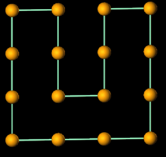
A simple 2d example of mapping an in principle non-periodic square into a 1d-torus of length 16 is shown in Fig. 6.
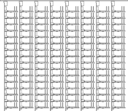
This process may be repeated, and an example of remapping a single motherboard is shown in Fig. 7. For any given machine it is possible to configure QCDOC for any application dimensionality from 1 to 6. From the point of view of the communications software, all partitions are six dimensional, but some variable number of these dimensions may be trivial. Calls in trivial application dimensions implement local copies from a node to itself, while calls in non-trivial application dimensions are mapped to the appropriate machine directions.
III.4 Performance of optimised code
In this section we present the performance of optimised code on cycle accurate simulation of QCDOC. Table 1 shows the performance of key single-node assembler kernels. Most of these assembler kernels were in fact generated via a C++ program which will also output Alpha and Sparc assembler. This allows a very fair comparison with other contemporary RISC chips.
| Operation | Mflops/node |
|---|---|
| SU3-SU3 | 800 |
| SU3-2spinor | 780 |
| DAXPY | 190 |
| ZAXPY | 450 |
| DAXPY-Norm | 350 |
| CloverTerm/asm | 790 |
| CloverTerm/gcc | 150 |
| CloverTerm/xlc | 300 |
| Operation | Local Vol. | Mflops/node |
|---|---|---|
| Wilson | 470 | |
| Wilson | 535 | |
| Clover | 560 | |
| Clover | 590 | |
| Staggered | 370 | |
| Staggered | 430 | |
| Asqtad | 440 |
Anecdotally, the phenomenal bandwidth from EDRAM allows the FPU performance of QCDOC on double precision floating point to match that of high end workstations from L2 cache.
The very low latency communication on QCDOC (circa 550 ns) allows for extreme scalability of QCD sparse matrix multiplies. Performance is very acceptable down to local volumes as small as , corresponding to a very spread out lattice. These benchmarks are shown in Table 2.
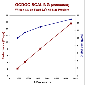
Finally, we display estimates of the scalability of a CG Wilson solver on large machines, including the 10 microsecond global summation time, in Fig. 8.
IV User software and performance
User software can access the hardware capabilities of QCDOC by linking to the run-time library provided. Optimized lattice QCD computation kernels as well as communication routines will be available. The software infrastructure, including run-time library and data management and execution environment, will be in compliance with the SciDAC lattice QCD software effort to ensure greater portability and efficiency for a wide range of codes not necessarily optimized for the QCDOC hardware.
IV.1 SciDAC software Program
The SciDAC National Computational Infrastructure for Lattice Gauge Theory initiative SciDAC is a multi-institutional effort to create the software and hardware infrastructure needed for Teraflop scale lattice QCD simulations.
The goal of the software effort is to create a unified programming environment that will enable the US lattice community to achieve high efficiency on diverse multi-Teraflop scale hardware platforms. More specifically, the SciDAC software effort aims at providing a run-time environment for existing lattice QCD codes such as the Columbia Physics System (CPS) CPS , MILC code MILC , or the SZIN software system SZIN so that they can be run and achieve high performance on various hardware platforms by adopting the programming environment provided by the SciDAC Software effort. A major part of this activity is to provide C and C++ API routines for lattice QCD (QCD-API) on which we will focus in this report. The performance of MILC routines with QMP on the QCDOC simulator is also presented.
The organization of the QCD-API is as follows.
-
•
Level 1:
-
–
QCD Message Passing API (QMP) : Inter-node communication
-
–
QCD Linear Algebra API (QLA): Single node linear Algebra
-
–
-
•
Level 2: QCD Data Parallel API (QDP): Lattice-wide operations with both communication and computation.
Example: parallel transport
for all and fixed , where is the fermion field at position and is the SU(3) gauge field connecting and . -
•
Level 3: Highly optimized routines for lattice QCD
-
–
Dirac matrix inverter
-
*
Wilson, Clover
-
*
Staggered
-
*
Asqtad (Improved staggered)
-
*
-
–
Hybrid Monte Carlo (HMC) Asqtad force term
-
–
So far, many Level 3 QCD-API routines as well as QMP have been optimized and implemented for QCDOC.
IV.2 Brief description of QMP
QMP aims to provide portable, low-latency, high-bandwidth communication routines suitable for lattice QCD. Here we describe some of the features of QMP. (For a more detailed description as well as for the C and C++ binding of the QMP routines, see Ref. QMP_doc .)
-
•
Point-to-point communication
-
–
Nonblocking (computation and communication can be overlapped)
-
–
Simultaneous, multi-directional transfer capability
-
–
Chained block/strided transfer capability
-
–
Separate routines for initialization and commencement of transfers opened communication channels can be reused to minimize overhead for repeated transfers
-
–
-
•
Global operation
-
–
Global reduction
Global Sum, Maximum, Minimum operations for integer, single and double precision numbers are available, as well as general binary reduction -
–
Broadcast
-
–
Barrier
-
–

Since QCDOC has optimized hardware for lattice QCD, it is crucial that the implementation does not introduce an excessive software overhead. For the nearest neighbor communication, the QMP specifications are close to QCDOC native calls, and the additional software overhead is small. Both C and C++ bindings are implemented over QCDOC system calls. This also applies to QMP global operations. These are implemented using the store-and-forward capability of QCDOC so that the communication time for global operations grows only as , where is the number of dimensions and is the number of sites per dimension. Currently, the implementation of QMP is complete except for non-nearest neighbor communication, which is discussed in the next subsection.
IV.3 Non-Nearest Neighbor Communication (NNC) on QCDOC
While communication patterns in lattice QCD are often to and from nearest neighbors only, a well optimized NNC QCD-API can be used for an implementation of routines with more complicated communication patterns, such as improved discretizations of the continuum QCD actions (Asqtad action asqtad ) and the MPI implementation on QMP (which is under way MPI_QMP ). However, additional software routines are needed to manage NNC on top of the QCDOC hardware where all high-bandwidth connections are only to nearest neighbors.
Some of the desired features for NNC are as follows:
-
•
Minimal buffer copying.
-
•
Minimal overhead over QCDOC native communication call when destination is nearest neighbor.
-
•
Capability to co-exist with nearest neighbor communication. Namely, both nearest and non-nearest communication can be open simultaneously and proceed without explicit user intervention or excessive delay on either communication channel.
The implementation strategy of NNC on QCDOC is as follows. After the outgoing data is packetized in the source node, the header is transferred and acknowledged via the interrupting communication channel (supervisor). The user data is then transferred using the non-interrupting physics network. If the receive node is not the destination of the packet, the packet is pushed onto the send/intermediate packets queue which sends the packets to the next node on the path until it reaches the destination. To avoid possible lock-ups and excessive delays, static, Manhattan-style routing is employed. It should be noted that in most lattice QCD routines, the communication pattern is uniform relative to the source, in which case Manhattan-style is close to being optimal. Figure 9 shows the data flow between QCDOC nodes in NNC. The implementation of NNC is under way MPI_QMP .
IV.4 Performance of MILC + QMP on QCDOC
MILC code MILC is a body of C codes for SU(3) gauge theory, developed and maintained by the MILC collaboration. It has been ported to various parallel computers, workstations, and communication protocols, including MPI and QMP. Implementation of the QMP back-end for the MILC code was done by James Osborne (osborn@physics.utah.edu). We ran several lattice QCD kernels in MILC code with QMP on the QCDOC simulator and measured the performance.
As shown in Table 3, 15 20% of peak performance is observed on the QCDOC simulator for many computationally intensive MILC C routines in single precision compiled by the XLC compiler XLC , which generated significantly more efficient assembly compared to GCC for PowerPC.
| Operation | Local Vol. | Mflops/node |
|---|---|---|
| Staggered | 170 | |
| Staggered | 210 | |
| Asqtad | 150 | |
| Asqtad Force | 140 | |
| Asqtad Force | 200 |
IV.5 Improved action (Asqtad) force term
The Asqtad action asqtad is one of the improved discretizations of continuum QCD fermion actions which exhibits smaller lattice spacing errors and flavor mixing. It uses many different paths connecting and or and in contrast to the Wilson or staggered actions where only one gauge link is used for each pair of neighbors. A diagram of the paths in the Asqtad action is shown in Fig. 10.

Calculation of the force term for the gauge link , , mostly consists of parallel transport and SU(3) vector outer products . Because of the complexity of the gauge paths used in the action, the number of floating point operations for the Asqtad force term is much larger than for the application of the Dirac operator and the force term for simpler actions. The number of floating point operations per site is 250,000. Considering that the number of Flops for the Asqtad Dirac operator is only 1146 per site, and the typical number of conjugate gradient iterations is about 1000 for the mass used in typical lattice simulations, the force term calculation is a significant portion of the Hybrid Monte Carlo simulation, where a Dirac matrix inversion is alternated with a force term calculation, and thus should be optimized as well as the Dirac operator.
We found the performance of the Asqtad force term was initially rather low, only 3% of peak for and 6% for local lattice volumes. Upon examining the source code, we found that the communication channels are being created and destroyed for each parallel transport. This amounts to 3060% of the total number of cycles for parallel transport. After modifying the parallel transport to reuse communication channels and combining small routines used in the outer product routine to eliminate function call overhead, the overall performance increased significantly to 12% for a and 13% for a local lattice.
Further optimization was done by eliminating function calls for computation routines defined for each lattice site within parallel transport and outer product routines. Together with loop unrolling, this made it possible to preload data into the L1 cache and registers to avoid cache misses. This improved the performance of computation routines by a factor of 1.51.7. The overall performance increased to 14% for and 20% for local volume, a 300400% increase over the original performance and quite acceptable for a C routine.
V Status and conclusions
QCDOC is a massively parallel computing architecture optimized for lattice QCD. The node has been designed to balance the floating point performance, memory bandwidth, and communication performance such that for QCD no single subsystem limits the performance. The design improves the network and memory subsystem performance relative to the floating point peak when compared with current commercial MPPs.
Simulation measurements of the nearest neighbour latency and global summation suggests at least an order of magnitude improvement over current commercial machines. This has enabled us to demonstrate very efficient use of the floating point unit that is maintained on remarkably small local volumes, such as , and estimate scalability on typical lattices to machines as large as several tens of thousands of nodes.
The six dimensional mesh network is dealt with transparently by the operating system, and the machine can be dynamically partitioned to run multiple applications of any dimension from one through six. This should enable applications with similar characteristics to QCD (local communication on a regular multi-dimensional mesh) to make efficient use of the machine.
A run-time environment compliant with the SciDAC software effort will be available. The message passing interface defined by the SciDAC effort, QMP, provides portable, efficient communication routines for lattice QCD. The QMP implementation on QCDOC is complete except for non-nearest neighbor communication, which is in the process of being implemented. Performance numbers for lattice QCD routines from MILC code with QMP were presented. To take full advantage of the hardware capabilities of QCDOC provided via QMP, the user programs should be written in a way that minimizes repetitive overheads, as shown by the performance numbers for the Asqtad force term.
The first batch of QCDOC ASICs has been manufactured and is being assembled for initial testing. While we thank the editors for their patience, we regret having been unable to further delay the submission of these proceedings until after the hardware went online. Performance figures obtained from real hardware will be available in the near future.
Acknowledgements.
This work was supported in part by U.S. Department of Energy contracts DE-AC02-98CH10886 (CJ) and DE-FG02-91ER40608 (TW), by the RIKEN-BNL Research Center (TW), and by PPARC (PAB).References
- (1) D. Chen et al., Nucl. Phys. B (Proc. Suppl.) 94 (2001) 825; P.A. Boyle et al., Nucl. Phys. B (Proc. Suppl.) 106 (2002) 177; P.A. Boyle et al., hep-lat/0210034
-
(2)
http://www-3.ibm.com/chips/products/
coreconnect - (3) http://www-3.ibm.com/chips/techlib/techlib.nsf/ products/PowerPC_440_Embedded_Core
-
(4)
http://www-3.ibm.com/chips/products/
powerpc/newsletter/aug2001/new-prod3.html - (5) http://www.scidac.org
-
(6)
http://phys.columbia.edu/cqft/physics_sfw/
physics_sfw.htm - (7) http://www.physics.utah.edu/detar/milc
- (8) http://www.jlab.org/edwards/szin/
- (9) http://www.lqcd.org/qmp/MessageAPI.htm
- (10) K. Orginos and D. Toussaint, Phys. Rev. D 59 (1999) 014501; K. Orginos, D. Toussaint and R. L. Sugar, Phys. Rev. D 60 (1999) 054503; G. P. Lepage, Phys. Rev. D59 (1999) 074502.
- (11) R. Bennet, in Proceedings of ”High Performance Computing with QCDOC and BlueGene”, BNL-71147-2003
- (12) http://www-3.ibm.com/software/awdtools/caix