HERA-B Status
M. Medinnis
DESY Zeuthen
Platanenallee 6
D-15738 Zeuthen
Germany
1 Introduction
HERA-B[1, 2] is designed for studies of B-physics at DESY’s HERA proton-lepton storage ring in Hamburg, Germany. The physics program calls for measuring production and decay properties of B and Bs mesons with emphasis on CP violation, particularly in the Bo J/ K decay channel.
Collisions of protons in the 920 GeV beam of HERA with a fixed target consisting of up to 8 wires surrounding the beam produce B-mesons whose decay products are measured in the HERA-B spectrometer. HERA-B will operate with a 40 MHz collision rate which, given HERA’s 10 MHz bunch-crossing rate, implies an average of 4 interactions per bunch crossing. A sophisticated multi-level triggering system is needed to reduce the overwhelming background from inelastic proton-nucleon collisions to a rate suitable for transfer of data to mass storage.
As of this writing (Dec. ′99), the experimental apparatus is nearing completion and the triggering system is being commissioned. This paper will briefly describe the experiment and summarize the current status of the major detector components. A more detailed account may be found in reference [3] and subsystem-specific papers in the same volume.
2 The detector
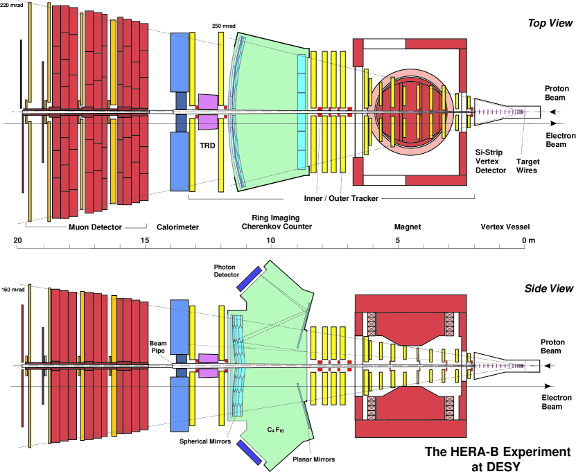
The apparatus is shown in Fig. 1. The proton beam enters from the right on the sketch and first sees the target wires then continues its journey through the spectrometer inside the 500 m thin aluminum beam pipe. Immediately downstream of the target, one finds the eight super-layers of the vertex detector which occupy the first two meters of the detector. A thin vacuum window is located just before the last station. The main tracking system starts immediately afterwards as does the large aperture main spectrometer magnet. The super-layers of the tracker are divided into inner and outer regions. The inner tracker covers the first 20 cm from beam center. The outer tracker takes over from there and extends the coverage to 250 mrad horizontally and 160 mrad vertically.
Three of the tracking stations shown in the magnet are a combination of cathode pad chambers (outer region) and gas pixel chambers (inner region) which will be used in the trigger for identifying high-pt hadrons. A RICH counter occupies the region between 8.5 m and 11.5 m. This is followed by another tracking layer, a transition radiation detector which supplements electron identification in the low-angle region, a tracking layer, then an electromagnetic calorimeter. The calorimeter is followed by a muon detector which is divided into three iron/concrete filters and 4 tracking stations. The muon trackers are divided into inner and outer sections in the manner of the main tracker.
2.1 Vertex detector system
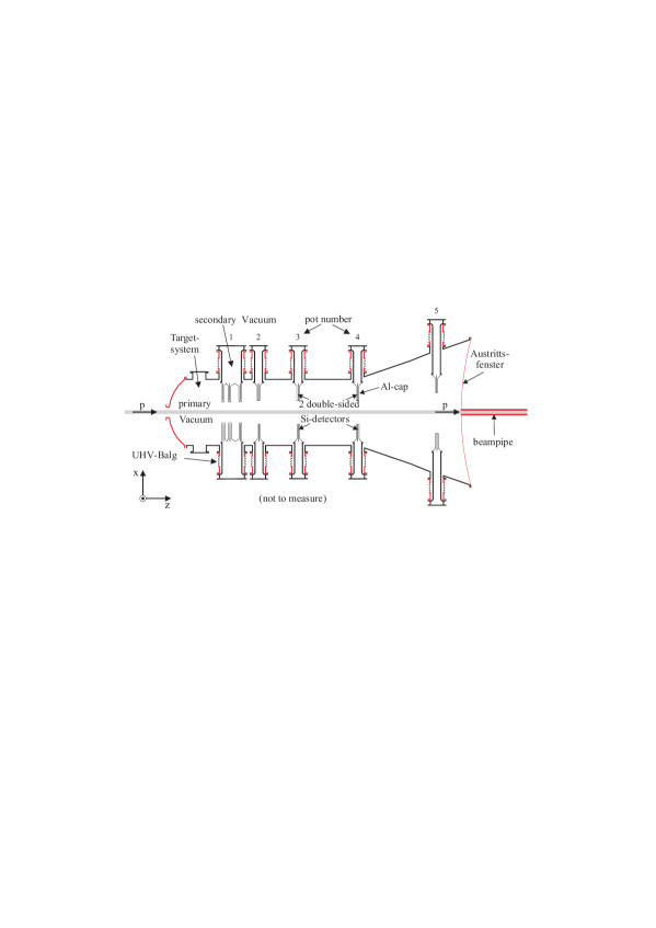
A horizontal section of the VDS is sketched in Fig.2. (A vertical section would look nearly the same.) Seven super-layers 111An eigth layer (not shown) is positioned just downstream of the exit window on an immovable mount. are each comprised of four “quadrants” each of which holds two double-sided silicon wafers. The wafers are configured as 50 m-pitch strip detectors with strips oriented at angles to the vertical or horizontal. The detectors are mounted in thin movable aluminum caps (so-called “Roman pots”) which can be moved away from the beam to allow for filling. The pots are evacuated but separated from the primary machine vacuum. When in their final positions, the outer perimeter of the 4 detectors of one super-layer describes a square centered on the beam with a square hole to allow passage of the beam.
Status: 85% of the detector has been operating routinely since summer of this year. The remainder is being installed in the present shutdown. The detector is performing well with signal to noise ratios of 20 or better.
2.2 Inner tracker
The original design called for a “classic” micro-strip gas chamber (MSGC) [4]. Early tests with x-rays showed that the chambers would withstand the anticipated dose rates for HERA-B but when tested in a hadron beam, the chambers sustained considerable anode damage due to sparking in a matter of hours. The problem was traced to heavy ions produced when charged tracks traverse the cathode/anode wafer. After some delay, a new design was found which uses a “GEM” foil (for gas electron multiplier) positioned between the drift electrode and the anode/cathode plane to provide additional gas amplification thus lowering the needed amplification in the region of the anode. Dose-related effects are still observed, nonetheless, the solution fulfils our requirements.
Status: Production and installation is underway with completion scheduled for February of next year. Several chambers have been installed, commissioned, and are operating on a regular basis. First analysis of data indicate that the chambers are meeting specifications. The readout electronics currently in use do not permit their forseen use in the tracking phase of the first level trigger. The readout of stations needed for the first level trigger will be upgraded in time for the running period of 2001.
2.3 Outer tracker
The outer-tracker is built from honeycomb drift modules with hexagonal cells of 5 mm and 10 mm. The cathodes are made from a carbon-impregnated resin “Pokalon-C ”. In situ tests of the chambers in 1997 revealed that the original design would not withstand the high radiation environment required for HERA-B operation and forced considerable additional R&D and substantial delays. Solutions to the various aging problems have since been found. The main departures from the original design are that the Pokalon-C is now gold-coated and a change of gas mixture was made, from from Ar/CH4/CF4 to Ar/CO2/CF4.
Status: All but one super-layer is now installed and operating routinely. Dead and noisy channel counts are of order 1%. The missing super-layer is scheduled for installation in January. The alignment and calibration is in progress.
2.4 RICH detector
Cherenkov light produced in the 2.5 m long C4F10 radiator gas is focused by an array of spherical mirrors onto focal planes of lens systems which then focus the light to an array of multi-anode phototubes.
Status: The detector is fully commissioned and in routine operation. The average photon yield for = 1 rings is 35, as expected.
2.5 Electromagnetic calorimeter
The calorimeter is of Shashlik design consisting of cells of 11 cm 11 cm transverse dimensions which are stacked to form a wall some 6 m in length and 4 m in height. The calorimeter is sub-divided into 3 regions. The cells of the innermost region use tungsten as a radiator and are viewed by a 5 5 array of phototubes. Both middle and outer sections have lead radiators. The cells of the middle region are viewed by 4 phototubes, and those of the outer region are serviced by a single phototube.
Status: The calorimeter is fully installed and equipped with phototubes. The inner and middle regions are also equipped with read out electronics. The read out is scheduled for completion by end January, 2000. The calibration is continually being refined and presently is about 7%.
2.6 Muon detetctor
The muon detector consists of 4 superlayers. The first 40 cm of each superlayer is covered by gas pixel chambers. The outer regions of the first two superlayers are covered by 3 double layers of tube chambers oriented at 0o and 20o with respect to the vertical. The third and fourth superlayers are of similar design but have, in addition, cathodes segmented into pads which are read out separately, for use in triggering.
Status: The system is fully installed and operational. Occupancies are as expected and coincidence rates between the third and fourth superlayers are also as expected.
3 Trigger and data acquisition
3.1 First level trigger
The task of the first level trigger (FLT) is to reduce the 10 MHz event rate (40 MHz interaction rate) by a factor of 200 with a maximum delay of 1.2 s. It works in three phases:
-
•
Pretrigger: Pretriggers originate from three sources: coincidences of pads and pixels in the 3rd and 4th superlayers of the muon detector, high-pt clusters in the calorimeter, coincidence patterns between the 3 pad chambers in the magnet. The three pretrigger systems produce “messages” which define a geometrical area (region-of-interest, or RoI) and an estimate of momentum. When operating at design rates, several such RoIs are expected per event.
-
•
Tracking: Messages from the pretriggers are routed to a parallel pipelined network of custom-built processors which attempt to track them through 4 of the 6 main tracker superlayers behind the magnet (and, for muon pretriggers, through the superlayers of the muon system). The processors map the superlayers geographically: each processor takes inputs from the 3 views of a contiguous region of a single superlayer. Messages are passed from processor to processor. In each processor, a search is made for hits inside the RoI and, when found, a new message is generated with refined track parameters and sent to the next processor (or processors when an RoI spans a boundary).
-
•
Decision: Messages arriving at the furthest upstream superlayer are “tracks” with parameters determined with a typical accuracy of a single cell width in the outer tracker and 4 strip widths in the inner tracker. These messages are collected in a single processor where they are sorted by event (at any given time, 100 events are being processed). A trigger decision is made based on the kinematics of single tracks and pairs of tracks. Events must be fully processed in less than 1.2 s.
Status: The inner and middle regions of the calorimeter are equipped with pretrigger electronics. First operation began more than a year ago and now, they are in routine operation. Completion is scheduled for end-January, 2000. The muon pretriggers have been tested with 15% coverage. Preliminary analysis indicates that the system is performing up to expectations. Completion is scheduled for mid-February. The high-pt system is under construction. Installation and commissioning will begin in January.
Production of the track finding units is nearing completion and installation is underway. A slice has been installed and exercised, analysis of data taken is underway. Full system commissioning will begin in January. If all goes well, the system should be at full power by March, 2000.
The trigger decision unit has been in routine use since summer of this year. Messages from the calorimeter pretriggers are routed directly to the unit which sorts them by event and triggers when more than two messages for one event are received.
3.2 Second and third level triggers, data acquisition
The SLT [5] is designed to work at an input rate of 50 kHz and supply a suppression of at least 100 and up to 1000 for trigger modes in which a detached secondary vertex is required. The 3rd level trigger is intended to provide a suppression of a factor of 10 on trigger types for which RoI-based cuts to not provide sufficient suppression – e.g. for events with no detached secondary vertex.
The SLT works on RoIs defined by the FLT, first gathering all hits within the RoI from all tracking layers behind the magnet and performing a fit. Successfully fit tracks are projected to and tracked through the vertex detector. At the end of the tracking process, a vertex fit is performed on track pairs. Also, the impact parameters of tracks relative to the target wires are estimated. Trigger decisions are made based on the outcome of the vertex fit and/or the track impact parameters.
The 2nd/3rd level trigger and data acquisition are integrated into a single system, implemented as a 240-node farm of standard Pentium processors running the Linux operating system, a high bandwidth switch, and a system of buffers (the “second level buffer”) which store event data while the second level trigger decision is being made. Both switch and buffers are built from the same DSP-based board.
Upon acceptance by the first level, an event is transfered to the 2nd level buffer and a processor node is assigned. The selected node performs the 2nd level algorithm, requesting any needed data by sending messages to the appropriate buffer module. Data of events passing 2nd level cuts are read from the 2nd level buffers into processor memory and the 3rd level trigger is performed. Events accepted at the third level are sent to the 4th level farm.
Status: The second level farm has been operating routinely for more than a year. The number of nodes in use currently stands at 80. All 240 nodes are installed and cabled to the switch. The installation will be finalized by end-January.
Portions of the 2nd level trigger algorithm have been exercised routinely in the last year. Events triggered at the 1st level as described in the previous section are transfered to the buffers. The assigned processor reads in the calorimeter data and searches for clusters with pt above 1 GeV. RoIs are generated and input into the vertex tracking code which requests hits from selected regions of the 2nd level buffers. Events for which at least one silicon track is found are transfered to mass storage.
The accumulated data were then analyzed by the offline analysis group. A plot of the mass of two silicon tracks (electron mass assumed) which match high-pt calorimeter clusters and have an electron signature in the calorimeter is shown in Fig. 3. A clear J/ peak is seen.

3.3 4th level trigger
The 4th level trigger is primarily intended for full online event reconstruction. Like the 2nd level, it consists of a farm of Pentium processors running Lynux. Unlike the 2nd level farm, it relies on standard ethernet technology for communication and data transfer. The design input rate is 50 Hz.
Status: In the last year, the event stream has been flowing through the 4th level farm on its way to mass storage. Several nodes are in use for doing partial reconstruction and data monitoring. The 200 node farm is complete and in use, in part for monitoring tasks and also for offline processing of data. The full reconstruction code exists and is being tuned in preparation for running on the completed farm in January.
4 Summary
HERA-B has suffered setbacks resulting primarily from unexpected aging effects in both inner and outer trackers. Solutions to these problems have been found and the spectrometer is nearing completion. In the meantime, considerable operational experience has been accrued in the running periods between monthly 3-day shutdowns for installation. After completion of the inner tracker in February, the detector will be ready for the start of the HERA-B physics program. The critical path is defined by the installation and commissioning of the first level trigger. We look forward to the start of data-taking for physics in February, 2000.
References
- [1] HERA-B Proposal, T. Lohse et al., DESY-PRC 94/02 (1994).
- [2] HERA-B Design Report, E. Hartouni et al., DESY-PRC 95/01 (1995).
- [3] HERA-B: Status and Commissioning results, C. Padilla, Proceedings of Beauty′99, Bled Slovenia, June 1999 (in press).
- [4] MSGC development for the Inner Tracker of HERA-B, T. Hott, Nucl. Inst. and Meth. A 408 (1998), 258.
- [5] Higher Level Trigger Systems for the HERA-B Experiment, M. Dam et al. IEEE Transaction on Nuclear Science. vol. 45, No. 4 Aug 1998.