UASLP–IF–99–01
Experimental Techniques††thanks: Course given at the VII Mexican Workshop on Particles and Fields, Merida, Yucatán, Mexico, November 10-17, 1999. Proceedings to be published by AIP.
Abstract
In this course we will give examples for experimental techniques used in particle physics experiments. After a short introduction, we will discuss applications in silicon microstrip detectors, wire chambers, and single photon detection in Ring Imaging Cherenkov (RICH) counters. A short discussion of the relevant physics processes, mainly different forms of energy loss in matter, is enclosed.
Introduction
In this course we will not try to reproduce standard text books about detectors (see for example jurgen:fernow ; jurgen:kleinknecht ) and descriptions of interaction with matter (a good summary can be found in jurgen:pdg ), covering in great details all aspects of experimental high energy physics. Due to the time restrictions ( were assigned by the organizers for this course) we will rather discuss examples on the use of some detector families. The selection is highly biased, since the author decided to use examples he knows best, e.g. he either worked on some of the detectors directly, or they were part of an experiment he participated in.
In a particle physics experiments detectors of various kinds are placed downstream (some even upstream) of the fixed target or surrounding a collision point of colliding beams. In general different detectors and electronic apparatus are required to perform the different tasks most experiment require: tracking, momentum analysis, particle identification, neutral particle detection, triggering, and data acquisition. Clearly a very important part is also the analysis of data, which comes in two parts: the event reconstruction, using all the detector information available (which requires for example a good alignment and calibration of all parts), and the final physics analysis. All these pieces cannot live by them self, to perform a successful experiment requires that all components, be it hardware or software, work all together to reach the final goal: A good and significant physics result.
Usually resources (both money and person-power) are limited when designing, building and operating an experiment. Careful consideration is necessary to decide, if some fancy or expensive detector is really necessary to obtain the physics goals or if a simpler, less expensive version would be sufficient, and the free resources can be applied to more essential parts of the experiments. Sometimes there are also political constraints that make a clear technical decision more complicated. All these arguments hold for the hardware as well as for the software part of the experiment.
In the following we will discuss generically MWPCs, the properties of a silicon microstrip array used in the SELEX experiment, and a longer part about RICH detectors used in WA89, SELEX, and CKM.
Multiwire Proportional and Drift Chambers
This section should be seen as an introduction to energy loss in matter and its use for particle detection, with these devices as examples.
Long time ago Geiger invented his counter: A charged particle will ionize gas, and the liberated electrons drift under the influence of an electric field to a thin counting wire. Close to the wire the field is strong enough to accelerate the electrons to ionize again further gas atoms or molecules (gas multiplication). In typical applications multiplication gains of or more can be obtained. The electrons drift to the wire, producing there a fast signal which is usually not resolved by the preamplifier, but the backwards drifting ions induce an additional, slower, signal, which can be easily detected.
Without any further consideration this will actually lead to a spark, usually something not welcome (but in the 60’s “spark chambers” where used for particle detection), since in the multiplication avalanche not only ions, but also excited atoms or molecules are produced, which will de-excite with the emission of a (UV)-photon, which can again ionize. Two tricks already used by Geiger help to avoid this: 1) A sufficiently large resistor is included in the HV line, so that the current drawn will lead to a voltage drop. 2) The addition of so-called quencher gases, usually some alcohol, to the detector gas, who will absorb the UV-photons without being ionized.
In the 60’s several groups, most famous the group around Charpak at CERN, started to develop counters later known as MWPC: Instead of one wire, a lot of wires are stretch parallel, with the electrons drifting to the nearest wire. This allows construction of larger area detectors, something necessary in the time when people tried to develop electronic detectors to replace the bubble chambers. The resolution of the detector is given by the wire distance, and space points can be obtained be putting MWPCs under different angles. In practice the wire distance is limited to about in small size chambers, and even more in larger areas for two reasons: The wires have to be stretched, supported by a strong frame, and, even stretched, electrostatic deflection has to be taken into account.
In the mid-60’s, a new idea came up, first realized in Heidelberg by Heintze and Walenta jurgen:Heintze : If the time a particle passes the counting gas is known, e.g. by using for example an scintillator somewhere in the experiment, the drift time of the electrons from the point of ionization to the wire contains also space information. Putting the wires further apart, and forming with cathodes a homogeneous electric field (with exception close to the wire), a constant drift velocity in the order of several is observed. The resolution, limited by the diffusion of the electrons, obtained with drift chambers can be well below , even with drifts of 10’s of cm. The advantage is clearly the reduced number of wires and readout channels, with the additional cost of the need of measuring the drift time with some sort of TDC.
The energy loss of moderately charged particles (other than electrons) in matter is primarily ionization. The mean rate of energy loss is given by the Bethe-Bloch equation:
| (1) |
Here is some constant, the charge of the particle, and the atomic number and charge of the medium, the maximum energy of a free electron after one collision, the mean excitation energy of the medium, and is a correction factor; the other symbols have there usual obvious meaning. is measured here in units of . The Bethe-Bloch formula only describes the mean energy loss; for finite path lengths, there are significant fluctuations in the actual energy loss. The distribution is skewed towards high values, described by the Landau distribution. Only for a thick layer the distribution is nearly Gaussian.
As seen from eq. 1, for the energy loss has a so-called “relativistic raise”. If the momentum of the particle is known, this can be used to identify the particle. The problem is that one has to sample the energy loss several times to be able to extract the average loss (Landau!). This is explicitly done in so-called “jet chambers”. An most up-to-date example is the OPAL central jet chamber jurgen:opala ; jurgen:opalb ; jurgen:opalc , where a normal track gets measured at 159 points, using long wires spaced by . The 3-dim space information (: wire number, : drift time, : charge division) gets used to measure the momentum (a magnetic field is present) and the total charge information helps to identify the particle. Another application is a TPC (Time Projection Chamber); the whole drift volume contains only gas with parallel electrical and magnetic field (to reduce the diffusion), and the electrons drift to the end plates, where wire or pads are used to obtain space information.
Silicon Microstrip Detectors
In the 1980’s, silicon microstrip detectors became used heavily in HEP. They are absolutely necessary to measure properties of particles containing charm and beauty quarks. Examples for very successful experiments using this kind of detectors include E691 at Fermilab, WA82 at CERN, and, in colliders, CDF, the 4 LEP experiments (Aleph, DELPHI, L3, OPAL), and the HERA experiments. Today there are a lot of experiments using silicon microstrips, with channel counts up to 1 million or more.
The detector allows to measure with a precision of down to a few the one-dimensional position of a passing charged track. Newer devices, the so-called pixel detectors, measure a two-dimensional position. The detector uses as basic detection device a pn-junction, shown in fig. 1 left,

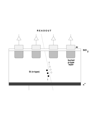
a diode which is operated in blocking direction with a sufficiently high voltage so that the entire device is depleted, e.g. there are no free electron-hole pairs (also called charge carriers). In one device several (up to several thousand) of these pn-junctions are operated, arranged in parallel strips. Should a charged particle pass through the detector (see fig. 1 right), new electron-hole pair are created and one of the carrier types will drift towards the nearest strip. In Silicon, the energy loss , and the energy needed to create one electron-hole pair is 111The band gap in Silicon is only , but Silicon is an indirect semiconductor., so in a typically thick detector about pairs will be created.
The construction of the detector itself seems to be under control today. There are several companies available which will produce the silicon detector with a well understood process. The smallest strip distance used today is , so that the structure is actually much simpler than the achieved sub-micron structures in todays semiconductor chips. The real challenge in these detectors is the readout: Imagine a detector with strip distance: 5000 strips with there small signals have to be readout. Every single strip needs a preamplifier, and some kind of signal detection like a discriminator, otherwise noise will overwhelm the data acquisition. To reduce the number of cables (anyway, how to have a cable every ?) it would be nice to chain several channels together, at best even all 5000. The chips should then be clever enough only to send a strip number to the data acquisition, e.g. the signal gets digitized and zero suppressed already at the detector.
A system like this, called SVX jurgen:lblsvx , was developed about 10 years ago by LBL for collider experiments (CDF), and also used in WA89 jurgen:wa89silicon and SELEX jurgen:prakash ; jurgen:selexsilicon . The basic layout of the SVX system is shown in fig. 2.

The current is integrated onto a capacitor as long as is closed. The charge is then transfered via a sequence of switch operations and compared to a pre-stored charge. If the signal charge is bigger, the channel offers its number to the readout. Up to 64 chips with 128 channels each can be chained for readout. Since this chip was developed for collider, the fact that the chip is integrating is not very important, since a clear cycle can be performed before every collision. In fixed target operation it is not known when an interaction will happen, so in general the chip will integrate several interactions until a clear cycle is performed, which has to be closely coupled with the trigger of the experiment since during a clear the detector is not sensitive. Depending on the beam rate, the number of interactions and the sensitivity of the experiment to out-of-time tracks, the ratio of integration and clear time has to be optimized for the experiment.
The layout of a typical fixed target vertex detector is shown in fig. 4.
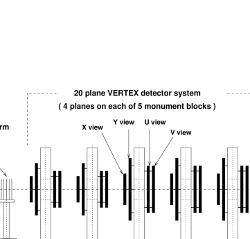

Tracks originating from the targets are transversing the silicon planes oriented in 4 different orientations (rotated by ) to allow the reconstruction of tracks in space. They eventually get fit to form a vertex, and the obtained resolution is shown in fig. 4. At high momentum the resolution is limited by the strip distance, but at lower momentum multiple scattering becomes more and more important. Nevertheless, the fit takes all error contributions correctly into account, as seen from a constant for all momenta. This is another lesson to learn: more detectors is not always good.
Another nice example is the silicon drift detector. The device developed for ALICE was presented in this workshop by E. Crescio jurgen:sildrift .
Ring Imaging Cherenkov Counters
Introduction
Even though the basic idea of determining the velocity of charged particles via measuring the Cherenkov angle was proposed in 1960 jurgen:ArtR , and in 1977 a first prototype was successfully operated jurgen:desrich , it was only during the last decade that Ring Imaging Cherenkov (RICH) Detectors were successfully used in experiments. A very useful collection of review articles and detailed descriptions can be found in the proceedings of three international workshops on this type of detectors, which were held in 1993 (Bari, Italy) jurgen:bari , 1995 (Uppsala, Sweden) jurgen:upsalla , and 1998 (Ein Gedi, Israel) jurgen:israelproc , respectively.
Charged particles with a velocity larger than the speed of light in a medium with refractive index will emit Cherenkov radiation under an angle , given by jurgen:cherenkov
| (2) |
with , being the speed of light in vacuum. The number of photons emitted per energy interval and path length is given by jurgen:franck
| (3) |
or, expressed for a wavelength interval ,
| (4) |
By measuring the Cherenkov angle one can in principle determine the velocity of the particle, which will, together with the momentum obtained via a magnetic spectrometer, lead to the determination of the mass and therefor to the identification of the particle222For this reason Cherenkov detectors are usually described under the chapter “particle identification” in particle detectors books..
Neglecting multiple scattering and energy loss in the medium, all the Cherenkov light (in one plane) is parallel, and can therefor be focused (for small ) with a spherical mirror (radius ) onto a point, as shown in fig. 5.

Since the emission is symmetrical in the azimuthal angle around the particle trajectory, this leads to a ring of radius in the focus, which is itself a sphere with radius . The radius is given by
| (5) |
The dependence of the ring radius on the momentum for different particles is shown in fig. 6

Since the number of photons is , most of the light is emitted in the VUV range. To fulfill equation 2, the refractive index has to be , so there will be no Cherenkov radiation in the x-ray region. Also it is very important to remember that is a function of the wavelength (, chromatic dispersion) and most materials have a absorption line in the VUV region, where , as shown in fig. 7, using Neon as example.

Since usually the wavelength of the emitted photon is not measured, this leads to a smearing of the measured ring radius, and one has to match carefully the wavelength ranges which one wishes to use: Lower wavelengths gives more photons, but larger chromatic dispersion.
A very useful formula is obtained by integrating eq. 4 over (or ), taking into account all efficiencies etc., obtaining a formula for the number of detected photons jurgen:desrich :
| (6) |
where is an overall performance measure (quality factor) of the detector, containing all the details (sensitive wavelength range, efficiencies), and is the path length of the particle within the radiator. A “ very good” RICH detector has , which gives typically around to detected photons () per ring.
The usual construction of a RICH detector is to use a radiator length of , e.g. equal to the focal length; but any other configuration, like folding the light path with additional (flat) mirrors is possible.
All the presented arguments and the drawing in fig. 5 only work for small , which is always fulfilled in gases, since only differs little from . Also important is the fact, that, should the particles not pass through the common center of curvature of mirror(s) and focal spheres, the ring gets deformed to an ellipse or, in more extreme cases, to a hyperbola. If the photon detector is able to resolve this, and the resolution is needed for the measurement, these deviations from a perfect circle have to be taken into account in determining the velocity . In general this effect can be neglected, and all parallel particles (with the same ) will give the same ring in the focal surface, due to the fact that all emitted Cherenkov light is parallel. The position of the ring center is determined by the angle of the tracks, not by their position.
In the following, we will describe two RICH detectors used in experiments, and a new application for RICH detectors for a new, proposed experiment. The author works or worked on all of them, so the selection is clearly biased. Even so, we feel that they are good examples for the use of this kind of detectors.
The CERN Omega-RICH
In the middle of the 1980’s, first attempts were made to apply the prototype results obtained by Séguinot and Ypsilantis jurgen:desrich to experiments in a larger scale. One of these attempts was performed at the CERN Omega facility in the West Hall. Experiments WA69 and WA82 tried to use this detector for there analysis, but only succeeded partly. An overview about this history can be found in jurgen:wa89bari . When in 1987 a new experiment, later named WA89, was proposed jurgen:wa89loi ; jurgen:wa89proposal , an important part was a necessary upgrade of this detector for the use by this new experiment. Two main parts where changed: New photon detectors using TMAE as photo sensitive component, and new mirrors to perform the focusing. Details about the detector can be found in jurgen:wa89bari ; jurgen:doktorarbeit ; jurgen:wa89wire ; jurgen:wa89upsalla ; jurgen:wa89israel .
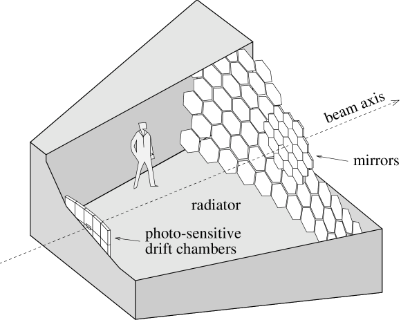
As seen in the overall layout of the detector (fig. 8), a RICH detector is basically a simple device: a big box, some mirrors at the end, and photon-sensitive detectors at the entrance.
The real challenge is to combine all the parameters together to obtain a perfect match for the overall system.
The size of the radiator box and the photon detector is given by the angular distribution of tracks which have to be identified at the location of the detector. Since usually this detector is placed behind a magnetic spectrometer, and the momentum spectrum of the interesting tracks depends on the physics goals of the experiment, the surfaces to cover have to be determined for every setup and experiment, usually with Monte Carlo simulations during the design phase of the experiment jurgen:doktorarbeit . In the case of WA89, the mirror surface needed was about , much smaller than the covered by the original Omega-RICH. It was therefor decided to replace only the central mirrors with smaller (as seen in fig. 8), higher surface quality mirrors to obtain better resolution.
The detector surface was calculated to be , with a spatial resolution of a few millimeters for every detected photon. The pixel size could therefor not be much bigger than also a few millimeters, leading to about pixels in the detector plane. The solution was to build drift chamber (TPC) modules, shown in fig. 9,

covering an area of , and approximating the focal sphere with a polygon of 5 modules. After passing a thick quartz window (to reduce absorption), the photons hit TMAE (see fig. 11) molecules,


converting via photo-effect into an single electron. TMAE is present with a concentration of about with the driftgas, which is otherwise pure ethan. The use of a quartz window together with TMAE as photo-sensitive gas leads that the detector is only sensitive in a small wavelength range between , as demonstrated in fig. 11. TMAE has a very low vapor pressure, so that at ambient temperatures the molecule is saturated within a gas. To obtain a short enough conversion length of around (otherwise the conversion would occur to far away from the focal plane and lead to an addition contribution to the resolution), the drift gas (ethane) is led through a bubbler, containing TMAE liquid at . This means that everything after the bubbler, e.g. the whole detector including radiator box, had to be heated to to avoid condensation. Other unpleasant properties of TMAE include a high reactivity with Oxygen, producing highly electro-negative oxides, which will attach an electron easily, change the drift velocity by a factor of several thousand, leading to a loss of electrons. Since the signal is a single electron (photo-effect!) this is catastrophic. The counting gas had an Oxygen contents of .
Mostly due to the presence of TMAE, the operation of this detector was not trivial. All parameters were monitored electronically, and hardware limits on some critical parameters (like temperature, Oxygen content of Ethane) lead to a automatic shutdown of the detector, waiting for an expert to arrive in the experimental hall.
Once the electron was released, it was drifting under the influence of an electric field of (drift velocity ) upwards or downwards over maximal towards long counting wires (gold-coated tungsten, diameter), spaced by . The two-dimensional spatial information about the conversion point of the photon is obtained with the position of the wire and the drift time of the electron. In total, 1280 wires were used in the detector. An additional complication was that the charged particles itself where passing through the chambers, leaving a signal of several hundred electrons, which is to be compared to the single electron which is our signal. This leads to increased requirements for the wire chambers (sensitive, e.g. sufficient multiplication, to single electrons, but no sparking with several hundred electrons) and to the preamplifier electronic (not too much dead time after a big pulse).
The overall resolution allowed the separation of pions and kaons up to a momentum of about , which was exactly the design goal. This lead to a good number of physics results jurgen:wa94a ; jurgen:wa89a ; jurgen:wa89b ; jurgen:wa89c ; jurgen:wa94b ; jurgen:wa89d ; jurgen:wa89e ; jurgen:wa89f ; jurgen:wa89g ; jurgen:wa89h , which would not have been possible to obtain without the RICH detector.
The SELEX Phototube RICH Detector
At Fermilab an new hyperon beam experiment, called SELEX, was proposed in 1987 jurgen:selexproposal . The key elements to perform a successful charmed-baryon experiments are 1) a high resolution silicon vertex detector and 2) a extremely good particle identification system based on RICH. During the following years, a prototype for the SELEX RICH was constructed and tested successfully jurgen:protos , based in some part on experience gained by our Russian collaborators jurgen:sphinx ; jurgen:sphinxnew . The real detector was constructed in 1993-1996, ready for the SELEX data taking period from July 1996 to September 1997. First results for the final detector were reported in jurgen:elba , and publications from this year contain all details and performance descriptions of this detector jurgen:bigrichpaper ; jurgen:israel .
A layout of the vessel is shown in fig. 12.

The radiator gas is Neon at atmospheric pressure and room temperature (see fig. 7), filled into the vessel with a nice gas-system jurgen:gassystem : First the vessel is flushed for about 1 day with (a cheap gas). After this the gas (mostly and little air) is pumped in a closed system over a cold trap running at liquid Nitrogen temperature, freezing out and the remaining water vapor. At the same time Neon gets filled into the vessel to keep the pressure constant. This part of the procedure takes about 1/2 day, and the vessel contains afterwards only Neon and about of Oxygen which is removed by pumping the gas over a filter of activated charcoal for a few hours, ending with an Oxygen contents of in the radiator. After this all valves were closed and the vessels sits there for the whole data taking of more than 1 year at a slight () overpressure333Actually the closed detector still sits untouched in the PC4 pit at Fermilab. We did not open it yet..
The mirror array at the end of the vessel is made of low expansion glass, polished to an average radius of , coated with Aluminum and a thin overcoating of , which gives reflectivity at . The quality of the mirrors was measured with the Ronchi technique jurgen:ronchi to assure a sufficient surface quality of the mirrors. The total mirror array covers and consists of 16 hexagonally shaped segments. The mirrors are fixed with a 3-point mount consisting of a double-differential screw and a ball bearing to a low mass honeycomb panel. The mirrors are mounted on one sphere, and were aligned by sweeping a laser beam coming from the center of curvature over the mirrors.
The photo detector is a hexagonally closed packed array of 2848 half-inch photomultipliers. A side view is shown in fig. 13.

In a thick aluminum plate holes are drilled from both sides, a deep straight hole holds the photomultiplier, and a conical hole on the radiator side holds aluminized mylar Winston cones, which form on the radiator side hexagons, leading to a total coverage of the surface. The 2848 holes are individually sealed with small quartz windows. For the central region of the array, a mixture of Hamamatsu R760 and FEU60 tubes were used, in the outside rows only FEU60 tubes are present. The nearly 9000 cables (signal, hv, ground) are routed to the bottom (hv) or top, where the signal cables are connected to preamp-discriminator-ecl-driver hybrid chips and finally readout via standard latch modules444Since the phototubes are detecting single photons, no ADCs are necessary..
A single event display of the detector is shown in fig. 15,
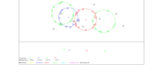

demonstrating the clear multitrack capability and the low noise of this detector. To analyze an event, the ring center is predicted via the known track parameters, and a likelihood analysis jurgen:likeli for different hypothesis (the momentum is known!) is performed to identify the particle. The final performance for this detector is shown in fig. 15. The detector is nearly efficient, even below the proton threshold the efficiency is above . In the SELEX offline analysis, the RICH is one of the first cuts applied to extract physics results. SELEX presented already several results at conferences jurgen:selexa ; jurgen:selexb ; jurgen:selexc ; jurgen:selexd ; jurgen:selexe ; jurgen:selexf , and one paper is submitted for publication jurgen:selexg .
Two RICHes for the CKM Experiment
Last year a new experiment called CKM jurgen:ckmproposal was proposed at Fermilab. The goal of the experiment is to measure the branching ratio for to an accuracy of (SM prediction is ) to measure the CKM matrix element . To withstand the high expected physics background, the experiment will use, in addition to a conventional magnetic spectrometer, a velocity spectrometer consisting of two phototube RICH detectors, one to measure the incoming , the second the outgoing . The design of the detectors is based on the SELEX RICH. The HEP group in San Luis Potosí is involved in the design, construction, and testing of parts of these detectors.
Acknowledgement
The author wishes to thank the organizers for the opportunity to present this course. This work was partly financed by FAI-UASLP and CONACyT. Figures 12, 13, and 15 are reprinted from Nuclear Instruments and Methods A431, J. Engelfried et al., The SELEX Phototube RICH Detector, pages 53-69, 1999, with permission from Elsevier Science.
References
- (1) R.C. Fernow, Introduction to experimental particle physics, Cambridge University Press (1986).
- (2) K. Kleinknecht, Detectors for particle radiation, Cambridge University Press, 2. english edition (1998).
- (3) C. Caso et al., Review of Particle Physics. Eur. Phys. J. C3 (1998) 1-794. http://pdg.lbl.gov
- (4) A.H. Walenta, J. Heintze, B. Schürlein, Nucl. Instr. Meth. 92 (1971) 373.
- (5) H.M. Fischer et al., The OPAL Jet Chamber Full Scale Prototype. Nucl. Instr. Meth. A252 (1986) 331-342.
- (6) H. Breuker et al., Particle Identification with the OPAL Jet Chamber in the Region of the Relativistic Rise. Nucl. Instr. Meth. A260 (1987) 329.
- (7) R.D. Heuer, A. Wagner, The OPAL Jet Chamber. Nucl. Instr. Meth. A265 (1988) 11-19.
- (8) P. Matthew, Construction and Evaluation of a high Resolution Silicon Microstrip Tracking Detector and Utilization to determine Interaction Vertices. Ph.D. Thesis, Carnegie-Mellon University, Pittsburg (1997).
- (9) S.A. Kleinfelder et al., Lawrence Berkeley Laboratory Note.
- (10) W. Brückner et al., Silicon -strip detectors with SVX-chip readout. Nucl. Instr. Meth. A348 (1994) 444-448.
- (11) J. Russ, et al., IEEE Trans. Nucl. Sci. NS36 (1989) 471.
- (12) E. Crescio, The ALICE Silicon Drift Detector. These proceedings.
- (13) A. Roberts, Nucl. Instr. and Meth. 9 (1960) 55.
- (14) J. Séguinot and T. Ypsilantis, Nucl. Instr. and Meth. 142 (1977) 377.
- (15) E. Nappi, T. Ypsilantis (Eds.), Proceedings of the First Workshop on Ring Imaging Cherenkov Detectors. Nucl. Instr. and Meth. A343 (1994) no. 1.
- (16) T. Ekelöf (Ed.), Proceedings of the Second International Workshop on Ring Imaging Cherenkov Detectors. Nucl. Instr. and Meth. A371 (1996) no. 1/2.
- (17) A. Breskin, R. Chechik, T. Ypsilantis (Eds.), Proceedings of the Third International Workshop on Ring Imaging Cherenkov Detectors. Nucl. Instr. and Meth. A433 (1999) no. 1/2.
- (18) P.A. Cherenkov, Phys. Rev. 52 (1937) 378.
- (19) I. Frank, I. Tamm, C. R. Acad. Sci. URSS 14 (1937) 109.
- (20) A. Bideau-Mehu et al., J. Quant. Spectrosc. Radiat. Transfer 25 (1981) 395.
- (21) H.-W. Siebert et al., Nucl. Instr. and Meth. A343 (1994) 60.
- (22) J. Engelfried et al., A high-statistics experiment on the U(3100) and on charmed-strange baryons. Letter of Intent CERN/SPSC/87-8, SPSC/I165 (1987).
- (23) A. Forino et al., Proposal for a new hyperon beam experiment at the CERN SPS using the Omega facility. CERN/SPSC/87-43, SPSC/P233 (1987).
- (24) J. Engelfried, Ph.D. Thesis, Heidelberg University (1992), unpublished.
- (25) W. Beusch et al., Nucl. Instr. and Meth. A323 (1992) 373.
- (26) U. Müller et al., Nucl. Instr. and Meth. A371 (1996) 27.
- (27) U. Müller et al., Nucl. Instr. and Meth. A433 (1999) 71.
- (28) R.A. Holroyd et al., Nucl. Instr. and Meth. A261 (1987) 440.
- (29) WA94 Collaboration, S. Abatzis et al., Strange Particle Production in Sulphur-Sulphur Interactions at per Nucleon. Nucl. Phys. A256 (1994) 499c-502c.
- (30) WA89 Collaboration, M.I. Adamovich et al., Measurement of the polarization of , , , and produced in a beam of . Z. Phys. A350 (1995) 379-386.
- (31) WA89 Collaboration, M.I. Adamovich et al., Measurement of the lifetime. Phys. Lett. B358 (1995) 151-161. hep-ex/9507004.
- (32) WA89 Collaboration, M.I. Adamovich et al., production by , and neutrons in the hyperon beam experiment at CERN. Z. Phys. C76 (1997) 35-44.
- (33) WA94 Collaboration, S. Abatzis et al., Charged Particle Production in – Collisions at c per Nucleon. Phys. Lett. B412 (1997) 148.
- (34) WA89 Collaboration, M.I. Adamovich et al., First observation of the decay mode of the hyperon. Eur. Phys. J. C5 (1998) 621-624. hep-ex/9710024.
- (35) WA89 Collaboration, M.I. Adamovich et al., Charge asymmetries for , and production in –nucleus interactions at . Eur. Phys. J. C8 (1999) 593-601. hep-ex/9803021.
- (36) WA89 Collaboration, M.I. Adamovich et al., First Observation of – elastic scattering in the hyperon beam experiment WA89 at CERN. Eur. Phys. J. C8 (1999) 59-66.
- (37) WA89 Collaboration, M.I. Adamovich et al., Production of resonances in induced reactions at . Accepted in Eur. Phys. J. C. hep-ex/9907021.
- (38) WA89 Collaboration, M.I. Adamovich et al., Determination of the Total Production Cross Section in c –Nucleus Interactions. Submitted to Eur. Phys. J. C. hep-ex/9908061.
-
(39)
J. Russ et al., A proposal to construct SELEX, Fermilab P781 (1987),
unpublished.
J. Russ, Nucl. Phys. A585 (1995) 99. - (40) M.P. Maia et al., Nucl. Instr. and Meth. A326 (1993) 496.
- (41) V.A. Dorofeev et al., Physics of Atomic Nuclei 57 (1994) 227.
- (42) A. Kozhevnikov et al., Nucl. Instr. and Meth. A433 (1999) 164.
- (43) J. Engelfried et al., Nucl. Instr. and Meth. A409 (1998) 439.
- (44) J. Engelfried et al., Nucl. Instr. and Meth. A431 (1999) 53-69. hep-ex/9811001.
- (45) J. Engelfried et al., Nucl. Instr. and Meth. A433 (1998) 149.
- (46) R. Richardson and R. Schmitt, Adv. in Cryo. Eng. 41B (1996) 1907.
- (47) L. Stutte, J. Engelfried and J. Kilmer, Nucl. Instr. and Meth. A369 (1996) 69.
- (48) U. Müller et al., Nucl. Instr. and Meth. A343 (1994) 279.
- (49) A. Kushnirenko, for the SELEX Collaboration, Charm Physics Results from SELEX. Proceedings of Heavy Quark 98.
- (50) SELEX Collaboration, I. Eschrich et al., Hyperon Physics Results from SELEX. Proceedings of Heavy Quark 98. hep-ex/9812019.
- (51) SELEX Collaboration, V. Kubarovski et al., Radiative Width of the Meson. Proceedings of ICHEP 98. hep-ex/9901014.
- (52) SELEX Collaboration, J. Russ et al.: First Charm Hadroproduction Results from SELEX. Proceedings of ICHEP 98. hep-ex/9812031.
- (53) SELEX Collaboration, F.G. Garcia, S.Y. Jun et al., First Charm Baryon Physics from SELEX (E781). Proceedings of DPF99. hep-ex/9905003.
- (54) SELEX Collaboration, M. Iori et al., Charm hadroproduction results from Selex. Proceedings of EPS-HEP99. hep-ex/9910039.
- (55) SELEX Collaboration, S.Y. Jun et al., Observation of the Cabibbo-suppressed decay . Submitted to Phys. Rev. Lett. hep-ex/9907062.
- (56) R. Coleman et al., CKM – Charged Kaons at the Main Injector – A proposal for a Precision Measurement of the Decay and Other Rare Processes at Fermilab Using the Main Injector. FERMILAB-P-0905 (1998), unpublished.