Measurement of the trailing edge of cosmic-ray track signals from a round-tube drift chamber
Abstract
The trailing edge of tube drift-chamber signals for charged particles is expected to provide information concerning the particle passage time. This information may be useful for separating meaningful signals from overlapping garbage at high-rate experiments, such as the future LHC experiments. We carried out a cosmic-ray test using a small tube chamber in order to investigate the feasibility of this idea. We achieved a trailing-edge time resolution of 12 ns in rms by applying simple pulse shaping to eliminate a signal tail. A comparison with a Monte Carlo simulation indicates the importance of well-optimized signal shaping to achieve good resolution. The resolution may be further improved with better shaping.
, , and ††thanks: Corresponding Author. E-mail address: shigeru.odaka@kek.jp.
1 Introduction
Tube drift chambers employing round tubes as the cathode electrode are frequently used as an important device for charged-particle tracking at large experiments, such as the Monitored Drift Tubes (MDT) in the muon detection system of the ATLAS experiment [1] at the Large Hadron Collider (LHC) to be built at CERN. Because of their simple structure, tube drift chambers provide us with easiness in construction and calibration. This is a great advantage for constructing a large detector system.
Along with such an advantage, tube drift chambers have an undesirable nature in applications to very high-rate experiments, such as those at LHC. They require relatively long time intervals to collect all meaningful signals. For example, this time interval (i.e., the maximum drift time) is expected to be about 500 ns in the case of ATLAS-MDT. This is appreciably longer than the planned beam-crossing interval of LHC (25 ns). Hence, the event data will be contaminated by garbage signals produced by particles from neighboring beam-crossings. In addition, since the environmental radiation tends to be severe at high-rate experiments, the data may suffer from continuous garbage produced by the radiation. These contaminations may deteriorate the track-reconstruction capability of the detector.
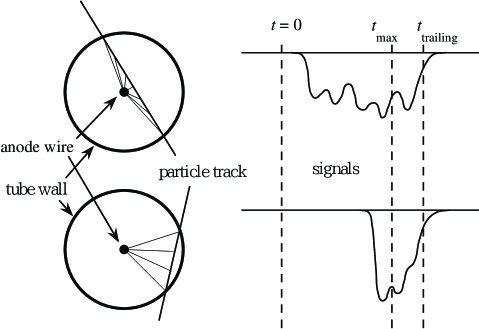
The source of signals from drift chambers is ionization electrons produced by charged particles passing through the chamber gas volume. The produced electrons drift towards an anode wire placed at the center to induce electrical signals via an avalanche process around the wire. The first arriving electrons, produced near the closest approach to the anode wire, form the leading edge of the signals. The leading edge, therefore, provides track position information.
On the other hand, if the response to single electrons is sufficiently narrow, the trailing edge of the signals is determined by those electrons produced near the tube wall. Thus, in the case of round-tube chambers, trailing edges appear at an approximately identical time with respect to the charged-particle passage, irrelevant of the leading-edge time and the incident angle, as schematically shown in Fig. 1.
This argument leads to a prospect that, if we can measure the trailing edge with a sufficient time resolution simultaneously with the leading edge, we may be able to distinguish the beam crossing relevant to each signal. In other words, we may be able to select only those signals relevant to an interesting beam crossing before applying reconstruction analyses [2].
In order to investigate the feasibility of this idea, we carried out a cosmic-ray test using a small tube drift chamber. The leading and trailing-edge times of the signals were simultaneously measured using a multi-hit TDC module employing the Time Memory Cell (TMC) LSI [3]. We discuss the observed properties, by comparing the results with predictions from a Monte Carlo simulation.
2 Setup for the cosmic-ray test
The tube chamber used for the test is made of a thin aluminum tube having an inner diameter of 15.4 mm, a wall thickness of 0.1 mm, and a length of 20 cm. A 3 mm-diameter window made on the tube wall near the center allows us to feed X rays into the tube. The window is covered with a thin aluminum foil and sealed with Kapton adhesive tape.
A gold-plated tungsten wire of 30 m in diameter is strung along the center axis of the tube. A positive high voltage was applied to the wire with the tube wall being grounded. A gas mixture of argon (50%) and ethane (50%) at the atmospheric pressure was made to flow inside the tube.
The signals from the tube chamber were amplified and discriminated using circuits made for the central drift chamber (CDC) of the VENUS experiment at KEK-TRISTAN, where a preamplifier board was attached to one end of the tube. The amplified signals were transferred to a discriminator board through a 30 m-long shielded twisted-pair cable. We added a pulse shaping circuit to the discriminator board, because no intentional shaping was applied in the original circuit.
The timing of the discriminated signals was measured using a 32-ch TMC-VME module [3] installed in a VME crate. This TDC module employs the TMC-TEG3 LSI [4], allowing us to measure both the leading and trailing edges simultaneously with a time resolution of 0.37 ns. The module also has an essentially unlimited multi-hit capability.
The TDC module was operated in a common-stop mode. Stop signals synchronized with the passage of cosmic rays were formed by a coincidence between signals from two scintillation counters, 10 cm by 25 cm each, vertically sandwitching the tube chamber with a separation of 15 cm. The coverage of this counter telescope was sufficiently larger than the tube chamber, providing a uniform track distribution in sampled data. As a trade-off, tube-chamber signals were observed in only about 20% of the data.
The data taking was controlled by a board computer installed in the VME crate. The computer collected the digitized data and stored them in a local disk. After completing the data taking, the stored data were transferred to a workstation through a network and analyzed there.
3 Pulse shaping
Before starting the test, we naively thought that appropriate pulse shaping would be necessary for trailing-edge measurements with a good time resolution, because of the presence of a long tail in drift chamber signals. The existence of a long tail, which may also be produced by readout circuits, would enhance the time-walk effect due to a large fluctuation in the gas-amplification process.
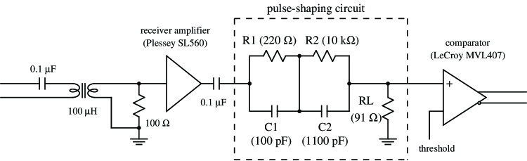
In order to eliminate the tail, we added a pulse shaping circuit between the receiver circuit and the comparator on the discriminator board. A diagram of the added circuit is shown in Fig. 2. The circuit is a double pole-zero filter, capable of converting two poles in the input signal into two new poles.
The parameters of the circuit were determined by using signals produced by the 5.9-keV X rays from 55Fe. The gas volume of the tube chamber was irradiated through the window on the tube wall, and the pulse shape at the discriminator input was investigated using a digital oscilloscope.
First of all, the pulse shape was sampled without adding the shaping circuit, and the observed signal tail was approximated by two exponentials. The circuit parameters were calculated so that the two zeros of the circuit should cancel the two time constants (poles) of the approximating function. Another constraint that we applied was that the amplitude corresponding to one of the newly produced poles, having a longer time constant, should become zero.

Ideally, a thus-determined circuit should replace a long tail in the input signal with one relatively short exponential tail. However, since the approximation with two exponentials has ambiguity, fine-tuning was necessary in order to achieve satisfactory performance. Looking at the resulting pulse shape, we adjusted the values of two resistors (R1 and R2), with capacitors (C1 and C2) and the other resistor (RL) fixed to the calculated values. The optimized parameter values are shown in Fig. 2. The pulse shapes measured before and after the shaping circuit are shown in Fig. 3.
4 Results
Due to a large fluctuation in the ionization and avalanche processes, discriminated signals for cosmic-ray tracks are sometimes separated into several fragments. In the offline analysis, successive signals were merged and considered to be one signal if the time interval between them (the interval between the trailing edge of the preceding signal and the leading edge of the following signal) was shorter than 40 ns.

Figure 4 shows the relation between the trailing-edge time and the leading-edge time of the recorded data. The data were obtained for an anode voltage of 2.0 kV and a discriminator threshold of 10 mV. The average pulse height for the 55Fe X rays was 750 mV for this anode voltage. Since about 200 electrons are expected to be produced by this X ray, the threshold corresponds to about three-times the average pulse height for one ionization electron.
We can see that the trailing edge of the signals exhibits a nearly equal time, irrespective of the leading-edge time, as expected. We can also find other interesting and unexpected properties in this result: as the leading-edge time becomes larger, the trailing-edge time resolution becomes better and the average time shifts towards larger values. Such properties are expected to emerge as the result of a geometrical focusing effect; i.e., the ionization electron density in the time domain becomes higher as the track distance becomes larger. In a real situation with a finite pulse width, this leads to a larger pulse height for signals having larger leading-edge times, resulting in a better time resolution and a longer delay of the trailing edge. However, as is shown later, this effect is not enough to explain the observed swing-up behavior at large leading-edge times.

Along with the dominant data points having a nearly equal trailing-edge time, we can see some data points distributed diagonally in the plot. Since the pulse-merging process is applied, they are not fragments of wider signals, but are isolated narrow signals. These data points gradually vanish as the threshold voltage is raised. They are apparently synchronized with the scintillator trigger. In addition, the frequency of these signals increases as the leading-edge time becomes larger, This suggests a uniform occurrence of the causal process over the chamber gas volume. These facts indicate that these signals were produced by soft X rays coming in association with triggering cosmic-ray muons. Therefore, they must have nothing to do with the chamber performance that we are now interested in.
Projections of the scatter plot are shown in Fig. 5, where the data points corresponding to those narrow signals described above are excluded. A flat distribution of the leading-edge time confirms a uniform distribution of the cosmic-ray tracks. The trailing-edge data are concentrated around about 40 ns after the maximum leading-edge time (the maximum drift time in the ordinary definition). From a straightforward numerical evaluation, we obtained an rms resolution of 12 ns for the trailing-edge measurement.
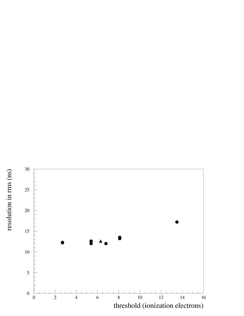
The measurement was repeated by varying the threshold voltage. Figure 6 shows the obtained rms resolution as a function of the threshold. We can observe that the improvement of the resolution by lowering the threshold is not significant. The improvement is limited by the swing-up behavior seen in Fig. 4.
5 Comparison with a simulation
We developed a simple Monte Carlo simulation, aiming at understanding the observed properties. In the simulation, a muon track passing through the chamber gas volume leaves ionization electron clusters along its path, according to a Poisson distribution with an average frequency of 3.0 clusters/mm. The number of electrons composing each cluster is subject to a Poisson distribution with an average of 3.0. The drift time of each electron is determined by the distance from the anode wire, assuming a constant drift velocity. The diffusion during the drift is not taken into account, since it is expected to be ineffective, compared to the measured time resolution.

The signal shape is simulated by convoluting the drift time distribution with a single-electron response, determined from the average pulse shape for 55Fe X rays. In the convolution, the pulse height for each electron is varied in order to simulate the gas-gain fluctuation. A Gaussian distribution was assumed for the fluctuation in the first version of the simulation. The leading and trailing-edge times are then determined by applying a threshold to the simulated signal shape.
A scatter plot obtained from the simulation, which should be compared with Fig. 4, is shown in Fig. 7, where the gain fluctuation was assumed to be 30% in the standard deviation. We can see in this result an improvement of the resolution and a shift of the average at larger leading-edge times. However, these variations are apparently less significant than those observed in the measurement result. Namely, the geometrical focusing effect, which is automatically included in the simulation, is not enough to reproduce the observation.
Aiming at a better reproduction, we applied several modifications to the simulation. The Polya distribution [5] was applied to make the gas-gain fluctuation more realistic. The threshold was made to fluctuate according to a Gaussian distribution in order to simulate a noise contribution. The diffusion of drift electrons was taken into account. Although these modifications could smear the overall time resolution, they could never enhance the swing-up behavior.
As a result of further studies, we found that a small overshoot in the shaped signal may produce an appreciable swing-up structure in the leading-trailing relation. The signal shape that we originally used in the simulation does not have any overshoot, because no significant overshoot was observed in the 55Fe X-ray response. However, any signal-shape measurement more or less affects the circuit property. There may be a small, but finite, overshoot in the real situation.

Figure 8 shows the result of a modified simulation in which the one-electron response is assumed to have an overshoot amounting to 5% of the peak pulse height. The overshoot is assumed to produce a baseline shift after the signal; i.e., the overshoot is assumed to have a very long time constant. The modifications concerning the signal fluctuation mentioned above are all applied in this simulation. The Polya distribution of a 100% fluctuation is used for the gain fluctuation. The standard deviation of the threshold fluctuation is equal to the average pulse height for one ionization electron. The swing-up behavior that we can see in Fig. 8 looks quite similar to that which we observed in the measurement data.

Projections of the plot are shown in Fig. 9. The trailing-edge time distribution has an rms resolution of 8.7 ns. This is still significantly smaller than that of the measurement result, suggesting that a further fine structure of the signal tail or certain phenomena not taken into account in the simulation (e.g., the -ray emission from the tube wall [6]) may be effective. Note that non-proportional effects, such as the space-charge effect, must not be significant, because a measurement with the anode HV lowered to 1.9 kV, for which the gas gain is reduced to about one half, gives a comparable result, as shown in Fig. 6.
6 Conclusions
A cosmic-ray test was carried out to investigate the feasibility of an idea of filtering tube drift-chamber signals at high-rate experiments, based on a trailing-edge time measurement. A small tube chamber filled with a popular chamber gas, Argon/Ethane (50/50), at the atmospheric pressure was used for the test. The leading and trailing-edge times of the signals for cosmic-ray tracks were measured simultaneously, using a TDC module employing the TMC LSI.
Applying a simple pole-zero filter circuit for signal shaping, we achieved a trailing-edge time resolution of 12 ns in rms with a realistic, or rather moderate, setting of the discriminator threshold. Measurements with a resolution of this level will be very useful at future high-rate experiments. In the case of LHC, such a measurement will allow bunch-crossing identification with a tolerance of two or three crossings without any significant loss of signals.
In the measurement data, we observed an unexpected correlation between the leading and trailing edges at large leading-edge times. This correlation limited the achieved trailing-edge time resolution.
From a simulation study, we found that a small overshoot in the signal tail can produce a correlation quite similar to that which we observed. If this is truly the reason, the resolution may be further improved with better signal shaping. Meanwhile, in the case of long tube chambers, this effect may seriously limit the achievable resolution, since the signal shape varies according to the signal transmission length. Further studies are necessary to confirm these arguments.
References
- [1] ATLAS Collab., W.W. Armstrong et al., The ATLAS Technical Proposal for a General-Purpose pp Experiment at the Large Hadron Collider at CERN, CERN/LHCC/94-43 (December 1994).
- [2] S. Odaka, talk at the Third JSD Workshop, KEK, Tsukuba, Japan, February 1 - 2, 1991.
- [3] H. Shirasu et al., IEEE Trans. Nucl. Sci. 43 (1996) 1799.
- [4] Y. Arai and M. Ikeno, IEEE J. Solid-State Circ. 31 (1996) 212.
- [5] W.S. Anderson et al., Nucl. Instr. and Meth. A323 (1992) 273; J. Byrne, Proc. R. Soc. Edin. A66 (1962) 33.
- [6] Y. Asano et al., Nucl. Instr. and Meth. A259 (1987) 438.