Particle Identification with BELLE
Abstract
The working principle and performance of the BELLE particle identification device (PID), based on a hybrid system consisting of an array of high precision scintillator Time of Flight and silica Aerogel Counters, is discussed. The performances achieved in the beam tests are satisfactory and Monte Carlo tests of meeting physics objectives of BELLE are promising. Prior to the real experiment which is expected to commence in spring 1999, the BELLE PID is taking cosmic ray data for calibration and fine tuning.
I Introduction
The new KEK asymmetric collider is scheduled to be fully operational in spring 1999. The BELLE experiment at KEK is in a preparatory stage of data taking and aims at either confirm or refute the present hypothesis of the Standard Model of CP violation in terms of phases in the Cabibbo-Kobayashi-Maskawa (CKM) matrix through a varieties of CP asymmetries in neutral and charged decays [1]. One of the most important task of the BELLE detector is the identification of the charged hadrons which is relevant for the reconstruction of many beauty and charm decay channels. This facilitates (1) the flavor tagging which relies on the correlation between the charge of kaon and the flavor of the decaying from which it is originated, and (2) identification of exclusive final states such as , that will provide a measurement of the angle in the unitary triangle. Since the relative abundance of pions and kaons in decays are approximately 8:1, the flavor tagging requires good kaon identification with minimal pion contamination. Also the type suppressed mode requires good separation from the penguin type decay such as which is of a similar magnitude.
Physics requirements divide the momentum coverage of charged hadron identification into two approximately non overlapping regions. Flavor tagging of the opposite though the detection of charged kaons produced in cascade requires kaon identification in the low momentum region i.e. between 0.2 GeV/c and 1.5 GeV/c (Fig 1). Due to the boost of the system the momenta range from about 1.5 GeV/c to 4.0 GeV/c for two body decays such as (Fig 2.)


In addition to the above requirement, the particle identification (PID)
system should have a minimum inactive material in front of the CsI(Tl)
crystal calorimeter to preserve the good energy resolution and detection
efficiency of soft photons. A sufficient sensitivity of signal to
noise over the full angular and momentum range would be an added
feature and the system must be able to operate efficiently in a 1.5 T magnetic
field.
Considering the above requirements, a hybrid system consisting of an array of scintillator Time of Flight (ToF) counters and an array of silica Aerogel Cherenkov Counter (ACC) has been chosen as the BELLE particle identification device where the ToF counters cover the momentum region below 1.2 GeV/c and ACC provide identification at higher momenta. This approach has an advantage of simplicity.
II The Time of Flight Counters
The subsystem consists of 128 Bicron BC408 Scintillator counters and 64 BC412 Trigger Scintillation (TSC) counters with fine mesh photo multiplier tubes (FMPMT) to read out the signals. By using the FMPMTs one eliminates the need for the light guides which gives a big reduction of time resolution. These modules are individually mounted to the inner wall of the CsI container at 1175 cm radius from the beam axis. The angular coverage of ToF is . They are used to start a clock and stop counting at a precise time ( with less than 100 psec time resolution ) after a beam crossing take place, thereby allowing the determination of the time it takes a particle to travel from the center of the interaction point to the ToF layer. This time, together with the knowledge of particle’s momentum from Central Drift Chamber (CDC), allows an estimate of particle mass and thus identity.
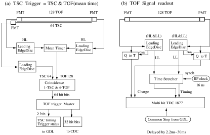
In addition to the -flavor tagging capability, ToF provides an event timing signal used by the trigger to provide a gate to the readout of other sub-detectors such as Electromagnetic Calorimeter (ECL) and CDC. Fig 3 shows the schematic diagram for the (a) fast trigger and (b) ToF readout. The FMPMT signals are read out into fast leading edge discriminators. A high level threshold discriminator is used to gate the low level timing signal. The signals are also read into MQT300A Charge to Time conversion chips. The BELLE standard readout board, LeCroy 1877s multi-hit TDC’s, are used to read out the signals from the MQT300A chip. These TDC’s have a least significant bit (LSB) of 500 ps. With the collaboration with LeCroy a ”Time Stretcher” modules have been developed [2]. The time stretcher expands a 25 ps LSB into a 500 ps LSB. By reading the timing information into the time stretcher and 1877s combination and performing the time walk correction, we have achieved 25ps resolution in the readout electronics which gives us a 100 ps overall timing resolution.
The forward and backward FMPMT timing signals of ToF modules are mean timed. The TSC timing signal is used to gate this mean time signal. The first mean time in the event is used for an on line event timing signal for the CDC and for fast reconstruction on the on-line farm. Xilinx pipelines are also used to calculate the event multiplicity and event shape (in ) for background reduction in the trigger.
A Results from Beam Tests
Full size prototype ToF counters (BC408 scintillators with attenuation length about 2.5 m ) were tested using a beam by placing the counter on a movable stage that could be rotated around a pivot point [3]. Fig 4 shows the time resolution as a function of beam position z. A time walk correction has been applied over all beam position and the time jitter of the start counter ( 35 ps) was subtracted quadratically. Intrinsic time resolution of 85 ps are obtained with a discriminator threshold set at 100 mV. Fig 5 shows the / separation for a 2 GeV/c un-separated beam. The observed 6 separation between and corresponds to what could be expected for / separation in a 1 GeV/c beam. The separation is improved near the FMPMT owing to the longer path length and better timing resolution.


III The Aerogel Cherenkov Counters
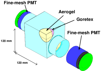
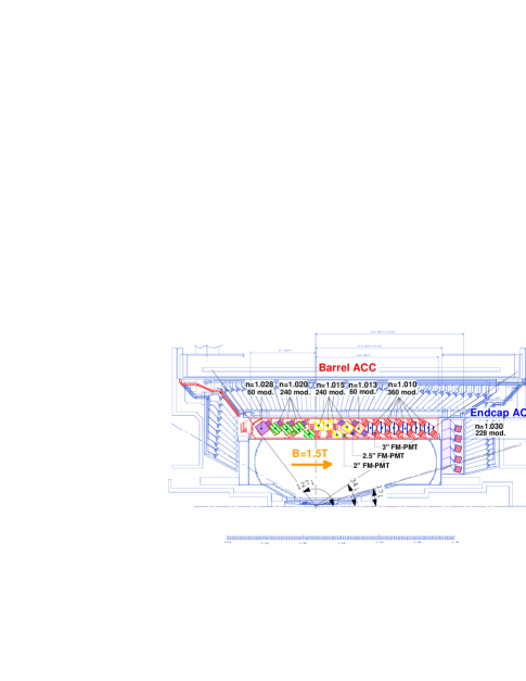
The ACC sub-system consists of 960 element-arrays (16 elements in and 60 elements in ) in the barrel and 268 element-array in the forward endcap. The barrel ACC (BACC) system is located between the CDC and CsI starting at an inner radius of 88.5 cm with the z coverage of -85 162 cm. The forward endcap ACC (EACC) is located between the forward endcap CsI and CDC endplate occupying the region bounded by 42114 cm and 116194 cm (Fig 7). Fig 6 shows the schematic of a single aerogel block in the array. Each aerogel block is made up of 5 layers of silica aerogel slabs housed in light-weight and light tight aluminum boxes. Being a Rayleigh scatterer, mean path lengths in aerogel are larger than in any non-scattering media. Therefore absorption in the aerogel and on the container walls is minimized by covering the wall with highly efficient white diffuse reflector (Gortex Teflon). Since the detector stays within a 1.5 T magnetic field, FMPMT are used to detect Cherenkov radiation. With a proper choice of refractive index, charged pions cause light to be emitted in the aerogel. The refractive indices for BACC varies with (n = 1.01, 1.013, 1.015, 1.020, 1.028) in a way that takes into account the general softening of the hadron momentum spectrum with increasing lab polar angle. All the EACC counters use n=1.03 aerogel that are appropriate for flavor tagging in the momentum region between 0.8 and 2.5 GeV/c. Table 1 summarizes the , and thresholds for different refractive indices used in the design. Around 3.5 GeV/c, also produces Cherenkov light and so separation of and becomes difficult in the forward direction when the particle has momentum more than 3.5 GeV/c. One can somehow get around the problem by looking at the pulse height information of the Cherenkov light since mesons tend to have larger pulse heights.
| n | [GeV/c] | [GeV/c] | [GeV/c] | |
|---|---|---|---|---|
| 1.010 | 0.985 | 3.482 | 6.618 | |
| 1.013 | 0.863 | 3.052 | 5.800 | |
| 1.015 | 0.803 | 2.840 | 5.397 | |
| 1.020 | 0.695 | 2.456 | 4.668 | |
| 1.028 | 0.585 | 2.072 | 3.937 | |
| 1.030 | 0.566 | 2.000 | 3.802 |
Besides having low refractive indices, the aerogels are hydrophobic - that ensures long term stability of the detector. In a separate test, aerogels were found to be radiation hard up to 10 MRad equivalent dose [5].
Since the gain of FMPMT drops sharply in high magnetic fields, one needs further amplification of the Cherenkov signal. Depending on the threshold, PMT signal from either ’s or ’s is amplified about 10 times before it goes to MQT300 chips. The output from the chips is fed to the Lecroy’s 1877s TDCs whose leading edge gives the timing of the pulse and the width is proportional to the pulse amplitude.
A Test Beam Results
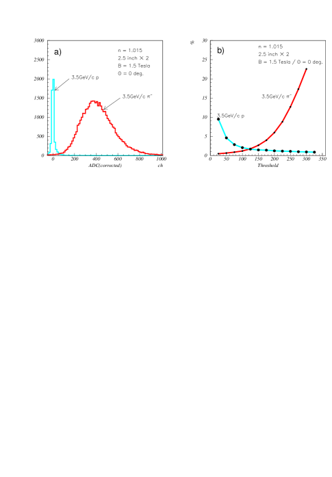
Fig 8 demonstrates the performance of ACC prototype achieved during a test beam operation with 1.5 Tesla magnetic field [3]. A pulse height distribution separating two 3.5 GeV/c charged particles, pions and protons, with
n = 1.05 aerogel is shown in Fig 8(a). More than 4 separation with efficiency better than 98 % can be achieved with less than 2 % background contamination which is mainly coming from proton induced knock-on electrons produced on the 1 mm thick aluminum box and aerogel material itself. It should be noted that in practice, unlike the beam test, the fake rate is dominated by hits on the glass window of FMPMT and showering in FMPMTs [4]. Fig 8(b) shows the efficiency and background contamination as a function of threshold on the pulse height. The average number of photoelectrons obtained for 3.5 GeV/c pions incident at the center of the counter was found to be 20.3 when viewed by two 2.5 inch FMPMTs. Considering the above results and the momentum dependence of Cherenkov light yield, we expect that more than 3 separation is possible in the momentum region of 1.2 to 3.5 GeV/c for BACC and 0.8 to 2.2 GeV/c for the EACC.
IV Simulation Results
To demonstrate that designed PID fulfills the various physics requirements, a number of simulation studies (both parametrized and detector based) has been done. Figure 8 shows an example of good separation between signal events when (a) (b) and backgrounds coming from the mis-identification of kaons, after the data are normalized to the same integrated luminosity.
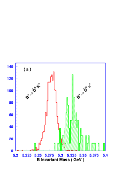
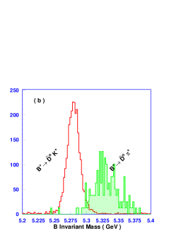
Similar simulation studies have been done for other decay modes that contain ’s and ’s in the decay products and the results are found satisfactory.
V Conclusion
A PID system based on hybrid system of ToF and silica aerogel counters is simple, robust and a powerful device that provides excellent particle identification over entire solid angle and momentum range. The detector has been constructed at KEK and being calibrated and tuned with cosmic ray events at a roll out position before the data taking with beam starts in spring 1999.
REFERENCES
- [1] BELLE Collaboration, A study of CP violation in decays, Technical Design Report, BELLE Collaboration, March 1995.
- [2] H. Kichimi and G. Varner, Design of ToF front end electronics, BELLE note 136.
- [3] BELLE Collaboration, BELLE Progress Report, March 1996.
- [4] R. Suda et al, Nuclear Instrum. Method 406:213-226, 1998.
- [5] S.K. Sahu et. al., Nuclear Instrum. Method A382:441, 1996.
- [6] A. Satpathy and M. Nakao, Experimental perspective of with BELLE, BELLE Note 245.