Beam-Induced Nuclear Depolarisation in a Gaseous Polarised Hydrogen Target
Abstract
Spin-polarised atomic hydrogen is used as a gaseous polarised proton target in high energy and nuclear physics experiments operating with internal beams in storage rings. When such beams are intense and bunched, this type of target can be depolarised by a resonant interaction with the transient magnetic field generated by the beam bunches. This effect has been studied with the HERA positron beam in the HERMES experiment at DESY. Resonances have been observed and a simple analytic model has been used to explain their shape and position. Operating conditions for the experiment have been found where there is no significant target depolarisation due to this effect.
pacs:
PACS numbers: 29.20.Dh, 29.25.PjNuclear-polarised hydrogen and deuterium gas targets deployed in high energy storage rings have become an important tool in the study of spin dependent processes in nuclear and particle physics experiments. They offer a unique combination of large nucleon polarization with the absence of other polarized or unpolarised nuclear species. A potentially serious practical consideration in the use of this type of polarised target in bunched beams is the nucleon depolarisation which can take place when the transient magnetic fields generated by the beam interact with the polarised nucleons and change their spin state. This can occur when the frequency of any large amplitude harmonic in the frequency spectrum of the pulsed magnetic field produced by the beam bunch structure coincides with an atomic hyperfine transition frequency determined by the local value of the static magnetic field which provides the quantisation axis for the nucleon spins. To minimise this depolarisation it is therefore necessary to provide static magnetic field conditions which ensure that no such resonant effects can occur within the effective target volume. These resonant depolarisation processes can be studied experimentally only with a fully operational target installed in a suitable storage ring. Beam induced depolarisation effects have been previously observed with tensor polarised deuterium targets [2, 3] in low energy electron beams in the VEPP-3 and NIKHEF accelerators. In this Letter we report on the first observation and measurements of beam-induced resonant depolarisation using a hydrogen target with a high energy positron beam in the HERMES experiment at DESY.
The HERMES experiment at DESY uses deep inelastic scattering to study the spin structure of the nucleon with polarised internal targets and a 27.5 GeV high intensity polarised positron beam in the HERA storage ring. The proton target is generated by injecting a nuclear-polarised atomic hydrogen beam from an atomic beam source (ABS) into a tubular open-ended storage cell which confines the atoms in the region of the circulating beam. The storage cell increases the probability of a positron-proton interaction by a factor of approximately one hundred compared with the free atomic beam. This results in a target thickness that is useful for HERMES with the atomic beam fluxes ( atoms s-1) which are currently available from polarised atomic hydrogen beam sources. A static magnetic field of approximately 335 mT directed parallel to the positron beam axis is provided throughout the target cell to define a longitudinal quantisation axis for the proton spins and to decouple the atomic electron and proton spins.
The HERA positron beam is optimised for collider operation and therefore consists of very short bunches with high peak currents. The beam has a time structure which allows for up to 220 bunches, which have a length of 27 ps (1) and are separated by a time interval of 96 ns corresponding to a bunch frequency = 10.4 MHz. The beam cross section at the target region is elliptical with a height of 0.07 mm and a width of 0.31 mm (1). Typically, the beam current has a maximum value of 45 mA immediately after injection, and is allowed to decay to 15 mA before the beam is dumped and the storage ring is refilled [4]. The frequency spectrum of the transient field has been calculated with the assumption that the magnetic field of each bunch has an approximately Gaussian shape in time. Hence the spectrum has the form of a harmonic series with a Gaussian shaped amplitude envelope. The bunch length is very short compared with the bunch separation; therefore the width of this envelope is large (6 GHz at 1) and very high-numbered harmonics have significant amplitudes.
In a magnetic field the hydrogen atom has four substates which are , , and , labelled to respectively. In normal target operation states and are selected to give positive (spin parallel to the static field) and and to give negative (spin anti-parallel) proton polarisations. In both cases the total electron polarisation is small. Loss of proton polarisation can occur if the resonance condition for either transition – or – is satisfied. The positions of the proton depolarising resonances as a function of static magnetic field can be deduced from the magnetic sub-state energies and have been calculated for the HERA beam bunch frequency as shown in Fig. 1.
To avoid beam-induced depolarisation in normal target operation, the value and the spatial uniformity of the static field must be chosen so that there are no resonances within the effective target volume [5]. The resonance separation increases as the field value is raised and it follows that the fractional uniformity requirement can be most easily satisfied if the highest possible value for the static field is used. However, practical considerations impose a limit on the maximum available field of approximately 350 mT for the HERMES target when operating in longitudinal mode. The spacing of adjacent resonances is approximately 50 mT in this region. Therefore, the target field magnet was designed to have a maximum value of 400 mT with a uniformity better than over the target cell volume.
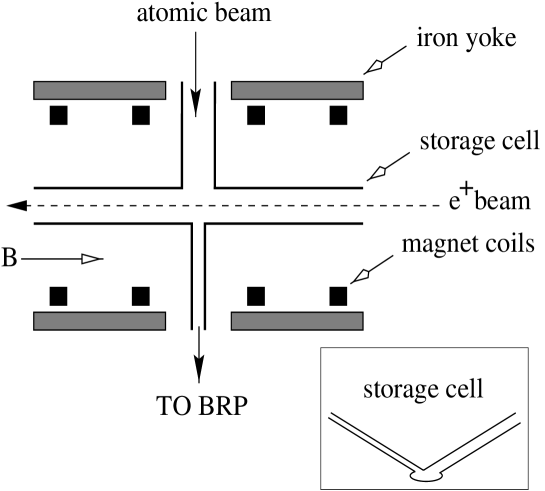
The basic layout of the target is shown in Fig. 2. The nuclear-polarised atomic beam from the ABS [6] is injected via a side tube into the centre () of the target cell, which is 400 mm long and has an elliptical cross section 29 mm wide by 9.8 mm high [7]. The atoms diffuse to the open ends of the cell at thermal velocities, generating a triangular density distribution along the beam axis. The escaping gas is removed from the storage ring beam tube by high speed vacuum pumps. The cell is cooled to approximately 100 K to maximise the target thickness, which is atoms cm-2 under normal operating conditions. The static field is provided by four superconducting coils mounted coaxially to the HERA positron beam, with a measured field profile along the positron beam axis as shown in Fig. 3.
The polarisation of a sample of the atoms in the cell is measured with a Breit-Rabi polarimeter (BRP) [8]. The sample flows out of a second side tube also connected to the centre of the cell. The BRP uses adiabatic RF transition units in combination with a sextupole magnet system, and a quadrupole mass spectrometer (QMS) incorporating an atom-counting detector to measure the magnetic sub-state populations. The nuclear and electronic polarisations may then be calculated from the population values obtained.
The resonances were observed experimentally by making measurements with the BRP over a range of static magnetic field values in the region of the normal operating field (335 mT), while the stored HERA positron beam was circulating through the target storage cell. Two different observation techniques were used. In the first approach, the ABS operated in the normal way and atoms in both states and were injected into the target cell. The BRP was then arranged so that states and were not detected by the QMS, with the result that any signal seen in this detector was due to the presence of states or . A statistically significant signal could be obtained in a short time with this technique, so it was possible to scan the field continuously and observe directly the position and shape of any resonant depolarisation signal. Measurements were made with stored positron beam currents between 38 and 28 mA. The field was scanned continuously over a range covering the full width of each resonance. A composite plot of the QMS signals produced by each of the resonances that occur in the field range between 220 and 400 mT is shown in Fig. 4. This shows that states other than and were being populated in the cell, clearly demonstrating the presence of resonant depolarisation effects. The observed resonances are at the expected values of the magnetic field within the experimental uncertainties.
The second method involves measuring the polarisation of the sampled atoms in the normal way by determining the individual populations of each of the four possible states in the sampled atomic beam. The proton polarisation could then be deduced from these data. This technique required the static magnetic field to be constant while the state populations for each point were measured. The resonance produced by the harmonic was studied in detail and the results are plotted in Fig. 5, which demonstrates the loss in the polarisation produced by this particular resonance.
The data were compared with a simple analytic model incorporating certain basic features of atomic kinetics in the target cell as well as the expected dependencies of the atomic transition probability on the time structure of the beam transient field as modulated by the atom’s passage through the beam [9]. Hence the shape of the resonances depends on the atomic density distribution within the cell, the static magnetic field profile and the BRP sampling sensitivity. A number of approximations were used to greatly simplify this many-dimensional problem. The fundamental approximation is that the effects of the beam fields on the atoms can be calculated with an average transition probability, which is appreciable only in close proximity to the beam, and at locations where the static magnetic field magnitude is at a resonant value. If the depolarisation is small so that each depolarised atom can be uniquely associated with the location in where it was depolarised, one can assume that the rate of depolarised atoms observed by the BRP can be calculated from the flux of atoms which enter the beam interaction region at position , , weighted by both the average transition probability at that location and the probability that any flux at position will be sampled at the BRP:
Then , where is the measured polarisation, is the polarisation in the absence of the HERA beam and is the total rate of atoms entering the BRP. The average transition probability is calculated to first order assuming that the perturbing transient field is purely transverse relative to the static field, and neglecting the effect of the changing vector direction of the transient field as the atom passes through the beam [10]. The transition probability
The frequency distribution is assumed to be a Lorentzian of width that corresponds to an average time of passage of an atom through the effective beam interaction region. is the calculated Fourier transform function and the frequency of the transient field. Only one harmonic in is relevant for any given resonance, and its line shape depends on the distribution of the bunch intensities in the stored beam. The operator contains the Pauli matrices for the electronic and nuclear spins which operate on the eigenstates and of the atom in the static field, with strength given by the appropriate magnetic dipole moment. In general, the positron beam will produce a transient field with amplitude which has a value increasing with the radial distance inside the beam and falling externally as . To simplify the analysis, is approximated by a constant throughout a hypothetical cylindrical interaction volume situated on the beam axis, and zero outside. The width varies inversely with the diameter of this volume.
In practice the prediction of the model is normalised to the data by an arbitrary factor which incorporates the perturbative field strength and the ratio . The width is a second fit parameter. A third fit parameter accounts for the relative contribution from the direct atomic beam compared to the diffusive flow of atoms. The flux has a triangular shape because the atoms are fed in at the centre of the cell. The sampling probability decreases linearly with the distance from the sampling tube and therefore has an identical shape. Fig. 5 illustrates how well the model can be fitted to the measured polarisation data. The best fit value of gives = 0.98 s, which corresponds to an interaction path length of 2.5 mm when the atoms are travelling with a thermal velocity corresponding to a temperature of 100 K. This value is compatible with the size of the effective interaction region.
The double peak structure can be simply understood by considering the profile in of the static field (Fig. 3), as resonance depolarisation is enhanced when it occurs where the gradient of the static field is small. When the magnet excitation current is high enough to place the central minimum in the field profile at the resonance value, a depolarisation peak is produced. The proximity of this resonance region to the sampling tube, together with the enhancement from direct flow, results in a larger depolarisation signal than in the case of the peak at lower magnet excitation, which arises when the resonant field value occurs in the two field maxima at 75 mm. The model result for the relative magnitude of these two peaks is sensitive to the third fit parameter.
In summary, we have observed depolarising resonances in the HERMES hydrogen target as expected from initial design studies made for the experiment. The features of the observed resonances are accounted for by a simple analytic model based on the target cell geometry, the profile of the target magnetic field and the nominal beam parameters. A working point for the target static field has been found between two resonances, where the beam-induced target depolarisation is undetectable at an uncertainty level below 1%. This demonstrates that a gaseous polarised proton target can be operated without significant beam-induced depolarisation effects in a stored positron beam having the very high bunch density required for collider operation.
We gratefully acknowledge the DESY management for its support, the DESY staff and the staffs of the collaborating institutions for their significant effort and our funding agencies for financial support.
REFERENCES
- [1] Deceased.
- [2] D.K. Toporkov et al, in High-Energy Spin Physics, proceedings of the International Symposium, Minneapolis, Minnesota, 1988, edited by K.J. Heller (AIP, New York 1988).
- [3] M. Ferro-Luzzi et al, Hyperfine Interactions, 110, 239 (1997).
- [4] HERA design report, Report No. DESY-HERA-81-10.
- [5] E. Kinney, in Proceedings of the Workshop on Polarised Ion Sources and Polarised Gas Targets, Madison, 1993, edited by L.W.Anderson and W.Haeberli (AIP, 1993).
- [6] A. Golendoukhin, in High-Energy Spin Physics, proceedings of the International Symposium, Amsterdam, 1996, edited by C.W.de Jager et al (World Scientific, 1997).
- [7] J. Stewart, in Proceedings of the International Workshop on Polarised Beams and Polarised Gas Targets, Cologne, 1995, edited by H. Paetz gen. Schieck and L. Sydow (World Scientific, 1997).
- [8] B. Braun, in High-Energy Spin Physics, proceedings of the International Symposium, Amsterdam, 1996, edited by C.W.de Jager et al (World Scientific, 1997).
- [9] H. Kolster, Ph.D. thesis, Ludwig Maximilians Universität München, 1998.
- [10] A. Abragam, The Principles of Nuclear Magnetism (OUP, 1961).