The Forward Proton Detector at DØ
Abstract
We present the first results of detector R & D done for the proposed Forward Proton Detector at DØ. From a menu of options we have chosen a scintillating fiber based detector with multi-anode photomultiplier readout.
†For the DØ Collaboration
I Physics Motivation
The interest in diffractive scattering has been growing since the observation of diffractive production of jets, by the UA8 collaboration[1]. This observation came in support of the recently introduced field of hard diffraction, in which the diffractive scattering is accompanied by high transverse momentum objects[2].
In principle such kind of events could be treated in terms of parton language, defining a partonic structure for the exchanged object. Diffractive events can also be characterized by rapidity gaps, regions of the phase space with no particles. This is due to the colorless nature of the exchanged object. Diffractive kinematics are summarized in Fig. 1.
The experimental difficulty in observing these events is that the scattered proton tends to remain in the beam pipe and can not be detected using the typical collider central detectors. For that it is necessary to add special forward particle detectors to the central assembly at very small angles, or large distances from the collision point.
Although rapidity gap techniques give some information on the diffractive event, only the addition of a forward particle detector would allow access to the full kinematics of the scattered particle.
Other motivation for adding a forward particle detector follows:
-
The Interest in Hard Diffraction has been growing dramatically due to recent results from HERA (H1, ZEUS) and Tevatron (CDF, DØ).
-
For the next 10 years much of this physics can only be done at the Tevatron collider. Diffractive systems with masses greater than 450 can be produced at Tevatron compared to only 70 at HERA.
-
Some processes like diffractive dijet production are well established, but not accurately measured.
-
Other processes like hard double pomeron exchange are not yet observed, but are likely to exist.
-
There are chances for discovery of new physics, like centauros, glueballs, etc.
-
Since there is little data on elastic scattering except at small t, such a detector could extend our knowledge to the high portion of the —t— spectrum.

II The Forward Proton Detector
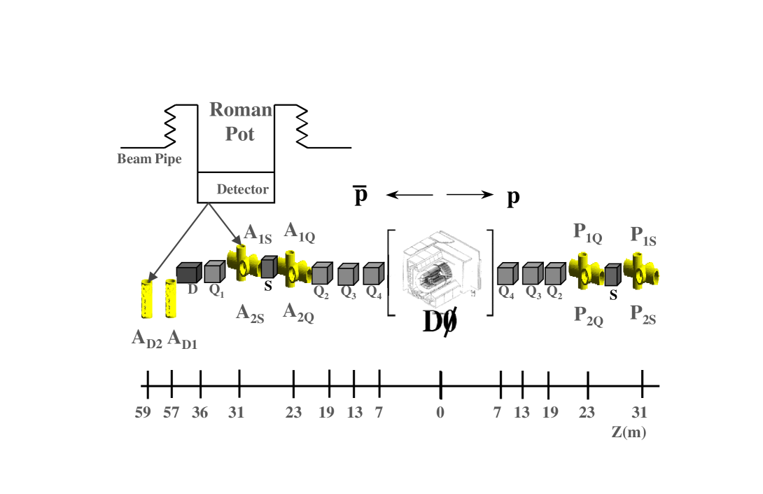
The Forward Proton Detector[3] is a series of momentum spectrometers that make use of machine magnets in conjunction with position detectors along the beam line in order to determine the kinematic variables (t and ) of the scattered protons and anti-protons. The position detectors have to operate a few mm from the beam position and have to be moved away during the machine injection time. Special devices called “Roman pots” are designed to house the position detectors allowing for remotely controlled movement with good accuracy. The Roman pots for the Forward Proton Detector are described in a separate work presented at this conference[4]. The greatest challenge for the use of these devices in our case, is the limited space available around the DØ interaction region.
Figure 2 shows a schematic representation of the location of the Roman Pots with respect to the DØ collision point. Spectrometers are labeled with respect to the analyzing magnet used. While the dipole spectrometer has detectors only in the horizontal direction, quadrupole spectrometers have detectors in both horizontal and vertical directions in order to maximize the acceptance.
This layout requires a total of 18 position detectors for both dipole and quadrupole spectrometers. It gives us the ability to trigger on both scattered protons and anti-protons while the hard scattering products are measured using the full DØ detector.
III Detector Goals
In order to characterize the hard diffractive events we need to be able to measure its kinematic variables to a good precision. However, external factors like the beam dispersion, uncertainty in beam position, multiple scattering and Roman Pot positioning limit the attainable resolution. Hence a point resolution of about 100m is sufficient for the Forward Proton Detector. Some desirable characteristics for this detector are listed bellow:
-
Overall efficiency close to 100%
-
Modest radiation hardness. The detector will be operating at approximately 8 ( is the beam standard deviation) from the beam axis, so the expected radiation dose for one year of running is only 0.03 Mrad.
-
High Rate capability. The detector needs to be live at every beam crossing.
-
Low sensitivity to accelerator background, in particular particle showering along the beam pipe or magnets.
-
Small dead area closer to the beam. This is particularly important since the protons are scattered at very low angles, so the detector acceptance is heavily dependent on its position relative to the beam axis.
IV Detector Options
We have considered several options for the position detector, some of which are listed bellow:
-
Silicon Microstrip Detector
-
Microstrip Gas Chamber (MSGC)
-
Scintillating Fiber Detector
In Table I we present some of the advantages and disadvantages of each of these detector options.
| Detector | Pro | Con |
|---|---|---|
| Silicon | Superior | Dead Area |
| Resolution | Trigger | |
| MSGC | Good | Dead Area |
| Resolution | ||
| Fiber | Adequate | Light |
| Resolution | Output |
Silicon microstrip detectors have very good resolution and can operate at high rates, however they have a high cost/channel and problems with dead area at the bottom of the pot (1mm), where acceptance is crucial. Also the readout time for this detector is not fast enough to use it in a Level 1 trigger, which we find necessary in order to reduce the event rates to an acceptable level.
MSGCs suffer from an even worse dead area problem as compared to silicon detectors. Reducing this dead area could be possible, but it would involve considerable efforts in Research and Development (R & D).
Scintillating Fiber Detectors do not present the dead area problem and can be read out using fast devices like photomultiplier tubes or photodiodes. A drawback of these detectors is the small light yield obtained from fibers that have a small enough diameter to give the desired position resolution. This can be seen from equation (1), which expresses the light yield as a function of several parameters, including the length of the fiber material traversed by the particle.
![[Uncaptioned image]](/html/hep-ex/9804005/assets/x3.png)
This problem can be overcomed by the use of very efficient photon detection devices, like the Visible Light Photon Counter (VLPC)[5], the Avalanche Photo Diode (APD), the Image Intensifier with CCD readout, and the Multi Anode Photomultiplier (MAPMT) among others. A comparison of the Quantum Efficiency (light to charge conversion) between these devices is given bellow.
| Device | Quantum Efficiency |
|---|---|
| VLPC | ( 80%) |
| APD | ( 70%) |
| Image Intensifier + CCD | ( 20%) |
| MAPMT | ( 20%) |
APDs are still in a development stage, especially for our application, which requires multiple channels in a single chip. Image Intensifiers with CCD readout cannot operate at the high rate needed by our detector. VLPCs, which were developed within the DØ collaboration, are by far the best option in terms of quantum efficiency, but the cost and complications of the cryogenics associated with it led us to the far simpler MAPMT. These devices have a reasonable sensitivity, high gain and can be operated at very high rates. We have chosen to use Hamamatsu H6568 16 channels MAPMT, which has single photoelectron (PE) sensitivity and good gain stability between channels.
Within the fiber framework we have investigated several options as detection elements:
-
A thin piece of scintillator tile connected to clear fibers for readout.
-
A thin piece of scintillator tile connected to wavelength shifting fibers for readout.
-
Scintillating fiber bundle straight from the detector area to the MAPMT.
-
Scintillating fiber bundle connected to clear fiber for readout.
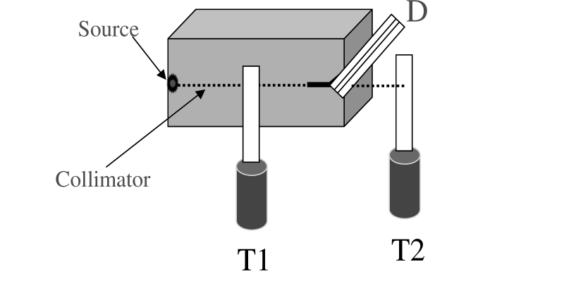
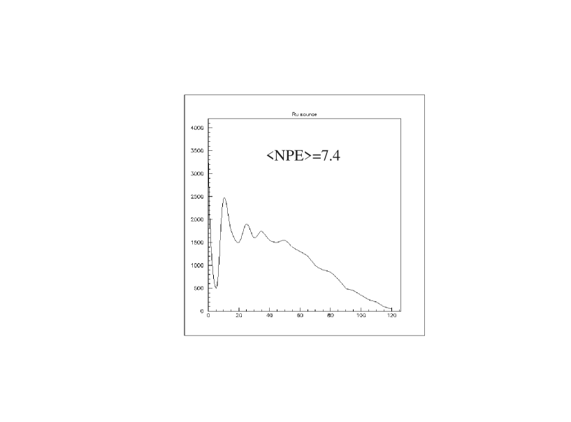
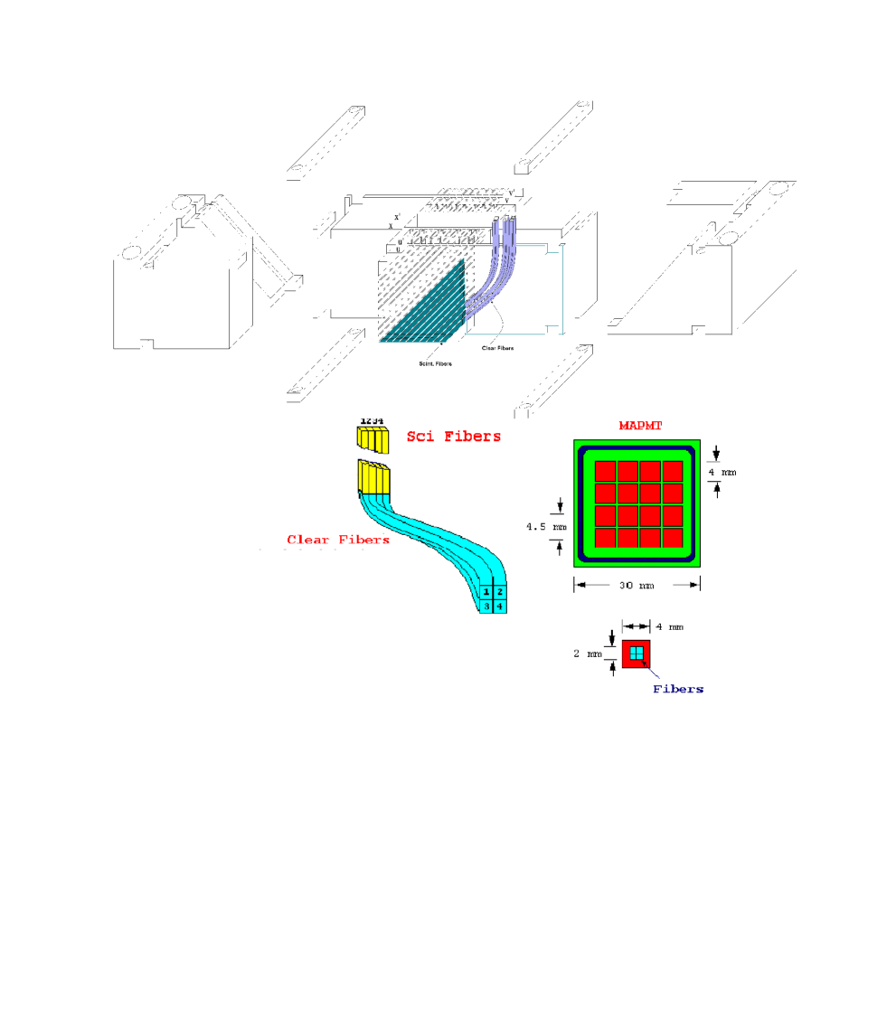
We have decided to use square fibers as opposed to round due to the fact that the former type gives an increase of about 20% in the light output. We use 0.8mm square fibers, giving about 80m point resolution, which is close to the desired value. The fibers were bundled in groups of four, since earlier studies have indicated that such an arrangement would give around 10 photoelectrons. In all cases one end of the detector element was aluminized to increase the light yield. Figure 3 shows a schematic drawing of the test setup used to compare different detection elements. All tests were done using and radioactive sources collimated to the fiber dimension. A single channel of the Hamamatsu H6568 16 channel MAPMT read out the four fiber bundles. Single PE calibration was done using a short pulse through a blue LED.
Results show a clear advantage in using scintillating fibers in comparison to a scintillator tile. This could be due to a possible lower trapping efficiency for the thin tile. We have also noticed that the thin tiles are very fragile, often developing several fractures even being handled with extreme care. Figures 4, 5 and 6 show the integrated charge for each of the options tested.
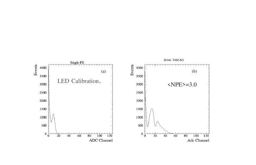
Figure 5 (b) shows the net effect of having the aluminized end of the detector cut at a angle. Having the fiber planes oriented at this angle (U, V planes instead of X, Y) would decrease the radius for the fiber bending, resulting in a more compact Roman Pot with the additional advantage of avoiding complicated pressure compensating mechanisms for this device. We can see that the effect of plane orientation is minimal.
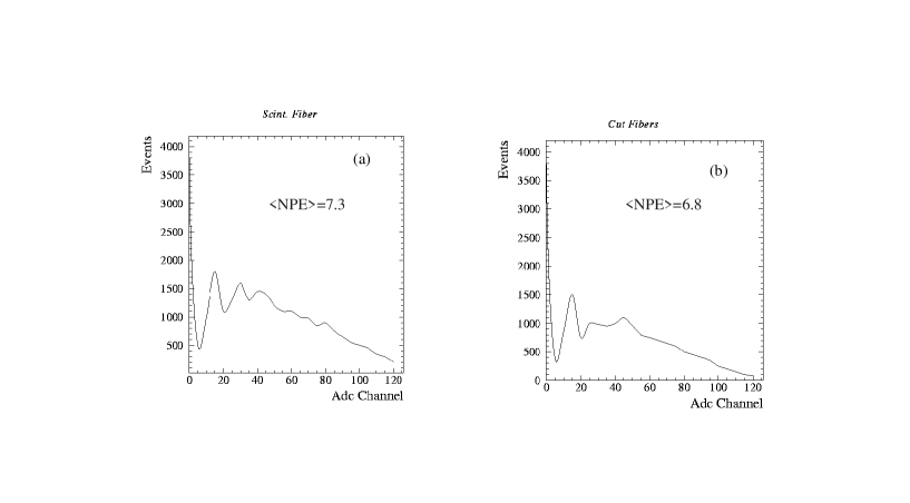
The setup using scintillating fibers spliced to clear fibers was chosen bearing in mind the effects of the halo background in the scintillating fibers alone, and also a slight decrease in the optical cross-talk with this setup. A comparison between Fig.6 and Fig.5 (b) shows that the scintillating plus clear fiber combination actually improves the light output due to the shorter attenuation length of the smaller scintillating fiber. Preliminary efficiency measurements done using the chosen setup range from 90-95%. This measurement does still have a residual photon background from the radioactive source and we are working on a cosmic ray setup to solve this problem. We have also detected a dependence of this result on the cutting, mirroring and splicing procedures, which have to be monitored carefully. The final detector configuration is shown in Fig. 7. There will be 6 planes in 3 views (U, V and X) in order to minimize ghost hit problems. The fibers will be mounted on a thin plastic frame, amounting to 112 channels per detector and a total of 2016 channels in all spectrometers. Each channel corresponds to 4 scintillating fibers, which fits nicely in the 4cm x 4cm-pixel size of the H6568 MAPMT. A total of 7 MAPMT will be needed for each detector, which represents the major component in the detector cost. This detector will allow us to make high-statistics and precise measurements of hard as well as inclusive diffractive processes, studying the dependence of these processes on kinematic variables. The combination of that with measurements in the central DØ detector will allow us to distinguish between different models for the pomeron structure.
V Conclusions
After considering several alternatives a scintillating fiber based detector with MAPMT readout was chosen as the best option for the FPD, considering all the aspects of acceptance, costs, radiation hardness and trigger capabilities. A prototype detector is being built at FNAL for resolution studies, and will be tested using a cosmic ray and, if available, a test beam setup. The FPD will add to the already existing diffractive physics program of DØ, being completely integrated to the existing detector.
The field of Hard Diffraction is in clear need of more precise data for a better understanding of the diffractive phenomena, and the FPD will certainly help to achieve this goal.
The arrangement of quadrupole and dipole spectrometers that we have chosen will extend the kinematic range of previous detectors, helps us in a better understanding of alignment and background issues, and could also be used for luminosity measurements.
REFERENCES
- [1] R. Bonino et al.(UA8 Collaboration)Phys. Lett. 211B (1988) 239. A. Brandt et al.(UA8 Collaboration) Phys. Lett. 297B (1992) 417.
- [2] G. Ingelman and P. Schlein Phys. Lett. 152B (1985) 256.
- [3] A. Brandt et al., “A Forward Proton Detector at DØ”, FERMILAB- Pub-97/377.
- [4] H. da Motta, “The FPD Roman Pot design”, This conference proceedings.
- [5] D. Adams et al., IEEE Trans.Nucl.Sci.,43 (1996) 1146.