The DISTO Data Acquisition System at SATURNE
Abstract
The DISTO collaboration has built a large-acceptance magnetic spectrometer designed to provide broad kinematic coverage of multi-particle final states produced in scattering. The spectrometer has been installed in the polarized proton beam of the Saturne accelerator in Saclay to study polarization observables in the ( or ) reaction and vector meson production ( and ) in collisions. The data acquisition system is based on a VME 68030 CPU running the OS/9 operating system, housed in a single VME crate together with the CAMAC interface, the triple port ECL memories, and four RISC R3000 CPU. The digitization of signals from the detectors is made by PCOS III and FERA front-end electronics. Data of several events belonging to a single Saturne extraction are stored in VME triple-port ECL memories using a hardwired fast sequencer. The buffer, optionally filtered by the RISC R3000 CPU, is recorded on a DLT cassette by DAQ CPU using the on-board SCSI interface during the acceleration cycle. Two UNIX workstations are connected to the VME CPUs through a fast parallel bus and the Local Area Network. They analyze a subset of events for on-line monitoring. The data acquisition system is able to read and record 3500 ev/burst in the present configuration with a dead time of 15%.
I Introduction
The DISTO collaboration has constructed a large-acceptance magnetic spectrometer to provide broad kinematic coverage of multi-particle final states involving charged particles produced in scattering. Examples include the measurement of polarization observables in reactions such as , with representing a hyperon or a hyperon resonance ( or ), and the study of vector meson ( and ) production in interactions [1, 2, 3, 4, 5, 6]. These measurements are now in progress at Laboratoire Nationale Saturne (LNS) in Saclay. In experiment LNS-E213, the high-quality polarized proton beam, with kinetic energies ranging between 1.6 and 2.9 GeV, hits a liquid hydrogen target positioned in the center of a magnet that provides a strong magnetic field with cylindrical symmetry. The Saturne accelerator provides, at 2.9 GeV, every 4 s a spill of protons with a flat top of 0.5 s. At 1.6 GeV the interspill time can be decreased down to 2 s. A sketch of the setup is shown in Fig. 1. Superimposed on the layout is a simulated event of the reaction .
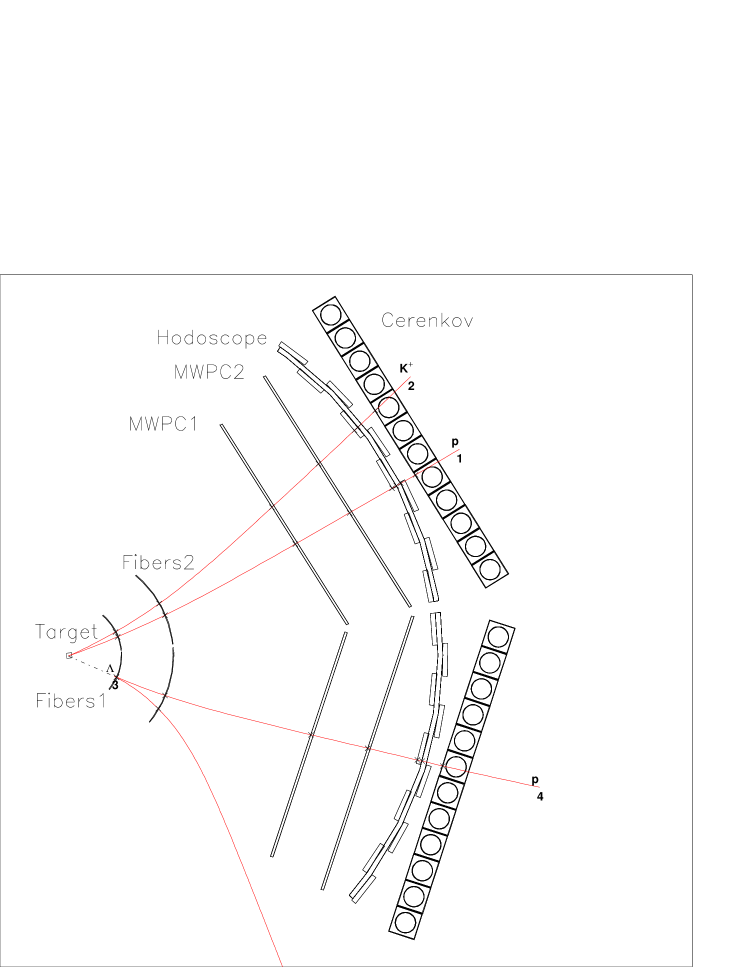
The detectors are arranged in two arms on both sides of the beam pipe (not shown in the figure). Tracking detectors comprise two pairs of cylindrical scintillating fiber (SF) chambers (two stereo layers, u-v planes, and one horizontal y plane) and two pairs of u-v-y planar Multi Wire Proportional Chambers (MWPC). The 2492 fibers and 3202 wires of the tracking detectors are equipped with discriminator/latch electronics (PCOS III). A scintillation counter hodoscope and a plane of vertically segmented Cerenkov counters follow the tracking detectors. The hodoscope and the fiber chambers feed the level-1 trigger that makes decisions based on the multiplicity of charged prongs and on the topology of the events. The 32 scintillation counters and the 48 Cerenkov counters are equipped with FERA ADC/TDC to allow readout of pulse height and timing information for particle identification.
II Overview of the DISTO DAQ Architecture
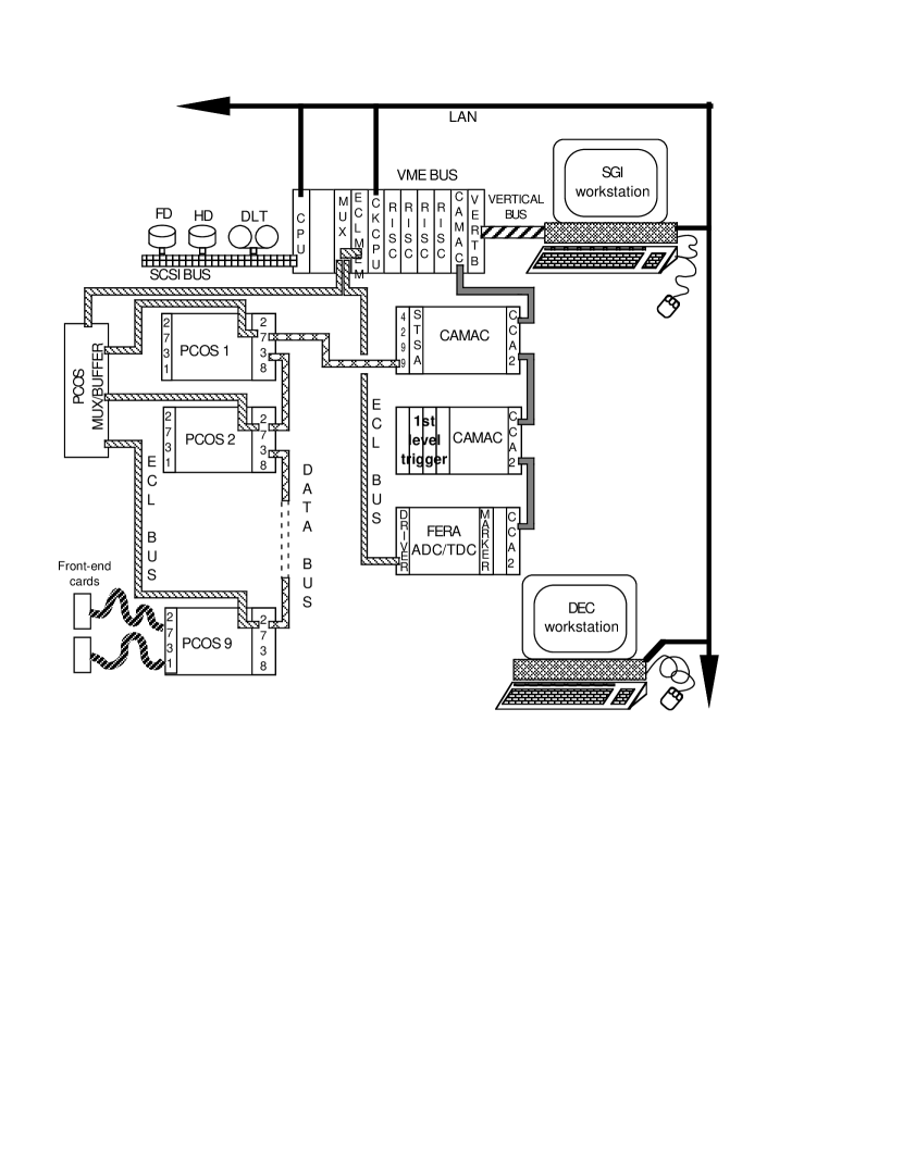
The data acquisition system, shown in Fig. 2, is based on a single VME crate, housing the data acquisition (DAQ) CPU, four RISC processors and the interface to the front-end crates. The DAQ CPU is connected to a Silicon Graphics (SGI) workstation through a parallel bus and to a DEC/Alpha workstation through a VME ELTEC [7] CPU and the Local Area Network (LAN) Ethernet line. The workstations permit on-line monitoring and control of the experiment. The VME CPUs and the workstations share the same disks using the NFS protocol.
The DAQ processor is a commercial VME board equipped with a 68030 CPU, the CES [8] model FIC8232, running the OS/9 operating system. It performs the following tasks:
-
•
set-up of the PCOS III and FERA front-end electronics through a standard CAMAC interface;
-
•
collection of events from a triple port ECL memory where they have been stored by the PCOS and FERA controllers during the Saturne extraction time;
-
•
dispatching of the events, via the VME bus, to the four RISC R3000 CPUs;
-
•
collection of events for tape recording on DLT cassettes through the on-board SCSI interface;
-
•
production of “spy” events for the monitoring workstations.
The on-line programs are written in FORTRAN and C and, as far as the monitoring is concerned, are based on the PAW [9] system developed at CERN. The optional R3000 filter algorithms are written and compiled on the SGI workstation, taking advantage of the same CPU used in both systems,and down-loaded through the parallel bus.
III DAQ components
The DISTO on-line data acquisition system architecture may be partitioned into several hardware and software components, discussed separately below.
A Data Acquisition Hardware Architecture
The DISTO hardware architecture, shown in Fig. 2, is made up of the following elements
1 Digitization electronics for tracking detectors
The MWPC and SF Multi-anode Photomultiplier’s outputs are digitized by the Multiwire Proportional Chamber Operating System (PCOS III) [10]. The system contains the circuitry to amplify, discriminate, delay, latch and encode the signals arriving from the tracking detectors. It includes 16-channel amplifier/discriminator cards (N277VG from Nanometrics [11]), 32-channel delay and latch modules (Model 2731A), a system controller (Model 2738) and a CAMAC DATABUS Interface and Buffer (Model 4299). This system allows very large data rates, by using fast encoding to process valid events extremely rapidly and high-speed transfer of the data at 10 MHz, 10 times the maximum rate of CAMAC.
The system uses the facility offered by PCOS III to allow computer control of discriminator thresholds and of the ripple-thru delays. The first option is used to measure the efficiency “plateau” of the chambers, the second one allows for an easy tuning of the delay in the coincidence circuits.
The 5694 channels are housed in 9 crates. The digitized data containing the the address of the hit wires are picked-up directly from the ECL output port of the system controller. The on-board multi-crate interconnection facility, which in principle allows daisy-chaining of up to 16 crates, was not used due to timing problem on the ECL ports when more than 5 crates were included in the assembly. Instead, a new FIFO/MULTIPLEXER module was specially designed to record the data of the 9 crates in parallel and write them sequentially on a single ECL output port. The 9 internal FIFO are able to record the 736 words per crate given by a crate completely fired. The 9 crates are interconnected, also, through the LeCroy DATABUS system. It is employed to send commands and set-up parameters to the PCOS system (logical address, threshold, delay and test pattern).
2 Digitization electronics for analog signals
The scintillation and Cerenkov counter’s analog information (charge and time intervals) are converted into digital format by the Fast Encoding and readout ADC (FERA) and Fast Encoding and Readout TDC (FERET)[10]. The heart of the system is the module 4300B, a charge sensitive 10/11 bit analog to digital converter ( conversion time of about ), the model 4301 FERA Driver and the model 4303 time-to-charge converter.
The 4301 FERA Driver distributes signals common to the system, such as gate, fast clear and handshake signals, via the command bus. It also receives data from the fast data bus, which collects data from all model 4300s in the system, and translates it for transmission via the on-board ECL-bus (10 Megawords/sec readout). The last 4300 module of the assembly is a special module able to write a flag word used as an event separator. The CAMAC data-way is used for status register and pedestal set-up, remote testing and control readout modes.
3 Event buffering system
The data are recorded in the dual daisy-chained triple port memory modules of the acquisition system via a 30-m long ECL-bus cable for high speed (10 MHz) readout. A special ECL bus multiplexer module was designed to allow fast switching of PCOS and FERA ECL signals sharing the same VME triple port memory.
4 Hardware arbitration system
The PCOS/FERA ECL-bus data multiplexing, the event busy flag signaling the digitization and read-out phase in progress, and the CPU read-out busy signals are made by several commercial and home-made NIM modules. The read-out of the buffer stored on the triple-port ECL memory by the data acquisition (DAQ) CPU is triggered at the end of the machine extraction cycle using a CAMAC STATUS-A module [12]. The STATUS-A module is the heart of the synchronization between hardware and software, it signals that raw data are ready to the acquisition task, end-of-readout, selects the acquisition mode (single event or multi-event for each readout), and starts, stops, and reset the scalers. Another CAMAC crate houses the programmable-threshold discriminators and logic matrices to select various level-1 triggers.
5 Multiprocessor system
The heart of the hardware architecture is a VME crate housing a multiprocessor system, memory and interfaces. The master CPU is the 68030 equipped with 16 MB of dual port RAM and connected by the SCSI bus to a 1GB HD through the OS9 operating system; this board carries out three tasks: the run-control, the acquisition program and the recording program.
A battery of four RISC CPUs R3000 carry out the optional run-time analysis and filter task to produce good recorded events. The task performed during this experiment is simply to swap the ECL-memory data.
A triple port 1 MB memory collects the data (single-event or multiple events per burst) from the front-end PCOS and FERA electronics using its ECL input. A 8210 CAMAC interface connects the 68030 CPU to the CAMAC, PCOS and FERA systems. The vertical bus VIC 8250 is used to insert the Silicon Graphics Workstation on the VME-bus, and the ethernet also links it to the OS9 68030 CPU.
6 Taping system
The medium used to record the data is “Digital Linear Tape” (DLT). It allows a very high storage capacity of 20 GBytes with hardware compression, high data transfer rates, fast seeking time, and last but not least, good reliability. It is connected to the DAQ CPU through the built-in SCSI-2 interface.
7 Trigger handshake
The DISTO trigger system, described in detail elsewhere [13], is completely managed by the DAQ system. Two configurations of trigger set-up were used throughout the experiment:
-
1.
multiparticle trigger for the and measurements.
-
2.
monitor trigger for elastic scattering reactions used to check and normalize the primary measurements.
The trigger is completely configurable by software by an independent program which produces two configuration files ready to be downloaded by DAQ to the level-1 trigger CAMAC modules. The number of beam spills for each trigger configuration can be selected at run-time by an appropriate choice of two parameters included in the set-up file.

B Data Acquisition Software Architecture
The DAQ software is organized as different tasks all running concurrently and cooperatively on different processors in the VME crate. The run control, recording and acquisition tasks run under the operating system OS9 on the 68030 processor. The PAW based monitoring task runs under UNIX in the SGI and DEC workstations and the 2nd level trigger task runs on a battery of four RISC CPU processors.
In the context scheme of Fig. 3 the structure of the system is shown together with its environment. DISTO_DAQ includes all the tasks, with the exception of monitoring, which together with the front-end electronics, the trigger system, the operator interface and the raw data analysis make up its environment. An overview of DISTO_DAQ is presented in Fig. 4.

The MANAGE READOUT is the central part of the acquisition. It receives RAW_DATA from the front-end electronics and creates the buffers for the 2nd level trigger, for the monitoring and for the raw data analysis processor. Moreover at the start of run it is able to initialize and check the dynamical hardware configuration and set all parameters. In the testing phase it can compute the FERA pedestals, the PCOS delays and execute front-end electronic tests. During acquisition the task is able to compute the trigger type and include or inhibit the FERA pedestal subtraction and zero and overflow suppression as determined by the configuration file. The hardware configuration parameters and all other information to set up the system (delays, thresholds, mapping logic addresses, pedestals, trigger type, etc.) are supported by disk files, which one can edit and download at the start of run.

Operation of the data acquisition system is managed by the Run-Control sub-system, consisting of a concurrent process and one operator interface. Run-Control manages all other DAQ sub-system tasks following a common state machine model with state transition corresponding to operator commands to start, stop, pause or end a run (period of data taking). A simplified state machine is displayed in Fig. 5. All the synchronizations between various tasks are performed by the use of shared dual port memories on the VME-bus.
1 Event Building
The event building is carried out by both hardware and software systems. (Fig. 2 and Fig. 4) First, the event components coming from the detector readout electronics are collected into two cascaded triple port ECL memories. In particular, the trigger signal makes the nine PCOS crates start to send their data in parallel to nine FIFO modules that subsequently transfers data sequentially on the ECL bus connected by the multiplexer to the ECL memory. Next, a signal switches the multiplexer input, linking it to the ECL bus coming from the FERA system. The FERA starts to send its data on the ECL bus to the memory, queuing them after the PCOS data. The last FERA data is the MARKER event separator, necessary because all events produced during the Saturne spill are queued in the same memory. At the end of this time a signal communicates to the acquisition task that the data of the burst are ready in the memory and the software phase starts.
The first step taken by the acquisition task is to build the event buffer, containing all of the events produced during the burst. Inserted at the top of the buffer is the header information: buffer length, run number, error types, trigger information and so on. Following the header comes scaler and register data. Last, PCOS and FERA data for each event, stored in the triple port ECL memory, are inserted. The complete buffer is delivered to the first free RISC processor running the second trigger level which produces a buffer optionally containing only filtered events ready to be saved on the tape. The same buffer is delivered to the SGI and DEC workstations for the raw data analysis processing. The buffer communication between the tasks is synchronized using software flags.
2 Monitoring system
The data taking was monitored using two independent systems. In the SGI workstation a sampling of the data is made to monitor the detectors performances and give an event display. The DEC workstation monitors the Cerenkov detector and gives another on-line event display. These tasks are made on both workstations under the PAW system [9] developed at CERN.
3 Run control system
The acquisition system task architecture is based on a states structure (Fig. 5). All the tasks are organized around the same algorithm state machine (ASM). Moreover the tasks are structured and organized around a hierarchical configuration. The ’Run Control’ (master task) controls the ASM, receives the operator commands by keyboard and delivers them to all other tasks (slaves). The tasks execute the operations expressed by the command and change the present state; at the end, all the tasks (also the run control) are always in the same state indicated by the ASM. The ASM is composed of 5 states:
- SLEEPING
-
This is an idle state; at the start all the tasks enter in this state.
- READY
-
In this state the system is ready for whatever operation.
It is possible to return to SLEEPING or to go to TESTING state to execute tests on the system hardware components or to go to the ACTIVE state to start data acquisition. - ACTIVE
-
This is the data acquisition state.
- TESTING
-
In this state the system can do several tests on all the system hardware components.
- PAUSE
-
It is the state to suspend (temporarily) the data acquisition.
The ’Run Control’ also has control of the general system state, continually monitoring the real task situation, showing possible abnormal conditions. The structure used to synchronize all the operations is a shared memory housed in the VME bus.
IV Performances
The DISTO Data Acquisition System architecture, in spite of its apparent complexity, is simple and compact. It has proven to be extremely efficient and fast due to the choice of putting some key components in hardware (such as digitization and buffering), therefore only a small part of the software has to manage the real-time aspects of the data flow.
At present the system is able to collect data at a rate greater than 10000 ev/burst with the FERA zero and overflow suppression (the PCOS is intrinsically zero suppressed). The event size is 240 bytes for the multiparticle trigger and 160 bytes for the elastic scattering monitor trigger. The trigger rate is presently reduced to ev/burst for multiparticle trigger and ev/burst for monitor trigger, by a sharp trigger topology request and beam intensity modulation, in order to minimize the off-line correction due to read-out dead-time. In production running of the experiment the mean read-out time is and, consequently, the dead-time is 15% for multiparticle trigger and 10% for monitor trigger. These rates were obtained for an instantaneous luminosity of cm-2 s-1.
V Acknowledgments
We wish to thank S. Gallian, and G. Maniscalco for their contribution to the DAQ and detectors electronic. We are moreover greatly grateful to G. Abbrugiati, G. Giraudo, and M. Mucchi, for their effort in the design and construction of scintillating fiber detectors. We are particularly indebted to N. Dibiase for the essential support since the beginning of the experiment. The continous help of the whole Saturne staff was essential for the success of this work.
References
- [1] J. Arvieux et al., Proposal 213 - Saturne (1991).
- [2] R. Abegg et al., Addendum 281 - Saturne (1993).
- [3] S. E. Vigdor, Flavour and Spin in Hadronic and Electromagnetic Interaction eds. F. Balestra, R. Bertini, and R. Garfagnini (1993) p.317.
- [4] J.Arvieux et al., Int. Symposium on Polarization Phenomena in Nuclear Physics eds. E.J. Stephenson and S.E. Vigdor, AIP Conf. Proceedings No. 339 (1994) p. 476.
- [5] R. Bertini, Nucl. Phys. A585 (1995) 265c.
- [6] A. Maggiora, Nucl. Phys. News Vol.5 No.4 (1995) 23.
- [7] ELTEC Elektronik GmbH, Galileo Galilei Straße 11, D-55129 Mainz, GERMANY.
- [8] CES S.A., 70, Rue du Pont Butin, PO Box 107, CH-1213 Petit Lancy 1, SWITZERLAND.
-
[9]
R. Brun et al.,
PAW – Physics Analysis Workstation,
CERN program library long writeup Q121. - [10] LeCroy Corporate, 700 Chestnut Ridge Road, Chestnut Ridge, NY 10977-6499.
- [11] Nanometrics Systems Inc., Oak Park, Illinois.
- [12] CAEN SpA, Viareggio, Italy.
- [13] F. Balestra et al., this proceeding.