The DISTO First Level Trigger at SATURNE
Abstract
The DISTO collaboration has built a large-acceptance magnetic spectrometer designed to provide broad kinematic coverage of multi-particle final states produced in scattering. The spectrometer has been installed in the polarized proton beam of the Saturne accelerator in Saclay to study polarization observables in the ( or ) reaction and vector meson production ( and ) in collisions. The common signature of such events is the multiplicity of four charged particles in the final state. A flexible 1st level trigger which uses topological information from fast detectors (scintillating fibers and hodoscope) has been built. It is completely software programmable through a menu-driven user interface and allows switching between production and monitor triggers on successive beam spills.
I Introduction
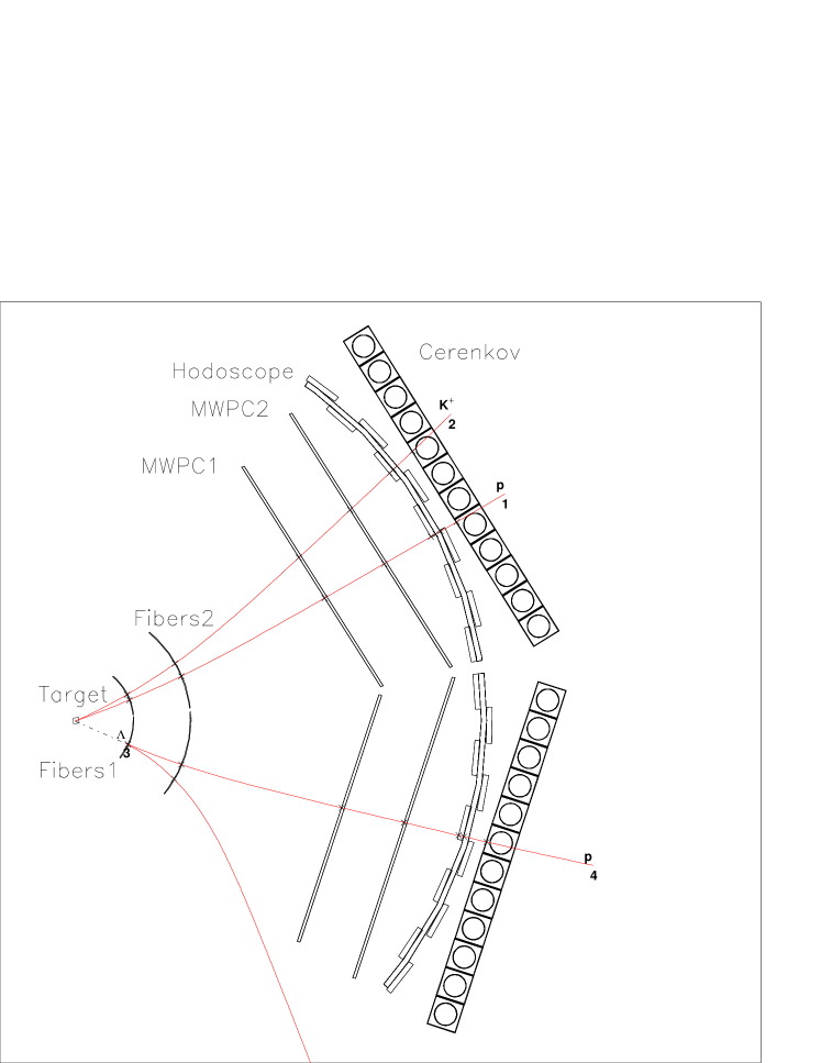
The DISTO collaboration has constructed a large-acceptance magnetic spectrometer to provide broad kinematic coverage of multi-particle final states involving charged particles produced in scattering. Examples include the measurement of polarization observables in reactions such as , with representing a hyperon or a hyperon resonance ( or ), and the study of vector meson ( and ) production in interactions [1, 2, 3, 4, 5, 6]. These measurements are now in progress at Laboratoire Nationale Saturne (LNS) in Saclay. In experiment LNS-E213, the high-quality polarized proton beam, with kinetic energies ranging between 1.6 and 2.9 GeV, hits a liquid hydrogen target positioned in the center of a magnet that provides a strong magnetic field with cylindrical symmetry. The Saturne accelerator provides, at 2.9 GeV, every 4 s a spill of protons with a flat top of 0.5 s. At 1.6 GeV the interspill time can be decreased down to 2 s. A sketch of the setup is shown in Fig. 1. Superimposed on the layout is a simulated event of the reaction .
The detectors are arranged in two arms, to either side of a curved beam pipe (not shown in the figure). Tracking detectors comprise two pairs of cylindrical scintillating fiber chambers (two stereo layers, u-v planes at and , and one y plane with horizontal fibers), two pairs of u-v-x planar Multi Wire Proportional Chambers (MWPC), a pair of cylindrical scintillation counter hodoscopes, and a pair of planes of vertically segmented water Cerenkov counter hodoscopes. Light from the scintillating fibers is converted to electronic signals in a number of 80-anode Hamamatsu photomultiplier tubes.
The 2492 fibers and 3202 wires of the tracking detectors are equipped with discriminator/latch electronics (LeCroy PCOS III). Pulse height and timing information from the 32 scintillation counter and the 48 Cerenkov counter photomultiplier tubes are read out via LeCroy FERA ADC’s and TDC’s. Logic signals from the scintillation hodoscope and the fiber chambers feed the level 1 trigger, which makes decisions based on the multiplicity of charged prongs and on the topology of the events.
II Overview of the 1st Level Trigger Architecture
The detailed scheme of the first level trigger is shown in Fig. 2. The front-end signals given by each detector are shown in the left part of the figure.

Different processing techniques are applied to the raw signals given by the triggering detectors in order to match the information with the first level trigger hardware setup. The hodoscope analog signals (R4 and L4) are directly sent to the counting room where they are processed by commercial programmable CAMAC discriminator and delay modules.
The information from the fibers is processed near the detectors before being sent to the counting room. The processing is different for the and for the and planes. The planes feed specially designed “Current Adder” NIM modules, described in detail in Section A, that are able to “spy” the ECL bus signals and sink a shaped 2mA signal (i.e. 100mV on 50 resistor) per hit fiber. These modules, together with commercial Linear Fan-in/Fan-out, generate a current signal proportional to the input multiplicity. The current signal given by the plane of each fiber chamber feeds a home-made “Dual Threshold Discriminator” (DTD) CAMAC module, described in Section A. The module gives a “true” logic signal when the input falls in a voltage window defined by two software progammable thresholds. Since the low and high thresholds are independently programmable, any -plane multiplicity configuration can be selected.
In contrast, the signals from the and fiber planes are simply OR-ed using the internal wired-or facility of PCOS latches. The overall logical OR from each and plane is then sent to the counting room, where the trigger can then demand only that at least one hit be registered on the corresponding fiber plane.
The DTDs and a special version of Current-Adder modules (without the internal shaper) are also used to get multiplicity information from different planes of the scintillation hodoscope.
The multiplicity logic signals of the fiber planes and the hodoscope planes feed three commercial “Logic Matrix Unit” (LMU) modules where any logical combination of input signals (AND, OR, AND/OR mixed logic) can be programmed.
An additional circuit, not shown in Fig. 2, synchronizes the data acquisition with the time structure of the Saturne beam: spills of 0.5 s duration separated by 3.5 s of acceleration overhead at the maximum energy of 2.9 GeV. In order to optimize the read-out throughput with minimal dead time, the level-1 trigger directly starts the front-end readout sequence (with PCOS first to allow for the slower FERA digitization) and the data are written, at 10MHz rate under a hard-wired arbitration system, into two daisy-chained, fast triple-port ECL memories (CES-8170). The intervention of the data acquisition CPU is thus required only at the end of the Saturne beam spill to transfer the buffer stored in the memory to a free second level trigger CPU and thence to the recording device. Using this operational mode we are able to reach a maximum acquisition rate of more than 10000 events per spill. However, in actual running conditions for the DISTO experiment, the multi-particle trigger rate has been kept below 3500 events/spill to maintain FERA digitization and readout dead times below 15%. These rates were obtained for an instantaneous luminosity of cm-2 s-1.
A special menu-driven interface, described in Section B, has been written to help the user program the trigger logic and multiplicity. The selected trigger choices are written into special files used by the data acquisition software to download into the trigger modules and copied into each event file stored on tape.
Taking advantage of the complete software programmability of the level-1 trigger system, it is possible in between successive beam spills to switch the experiment trigger from the main reaction to a monitor reaction without introducing any additional dead time. Indeed, we normally take data with a multi-particle trigger for 90% of the Saturne spills, and with a different p-p elastic trigger for the remaining 10% of the spills. The p-p trigger is defined with the aid of a commercial memory lookup module, used to identify the angular correlation characteristic of elastic scattering kinematic coincidences in the hit pattern of the scintillation hodoscope elements.
A The 1st Level Trigger Hardware
Two special modules have been designed for the first level trigger of the DISTO experiment.
The first one is the “Current Adder” shown in Fig. 3. The main purpose of this module is to sample the ECL signals coming from fiber chamber front-end cards, on their way to the PCOS latch modules. The width of the input signal is internally shaped to 30ns to span the time ranges associated with intrinsic jitter of the photomultiplier signals and different lengths of delay cables and optical fibers. A high-impedance input driver is used in order to not disturb the proper termination of the signal at the PCOS input. The output circuitry is able to sink and add a current of 2 mA per hit. Up to 48 channels are housed in a single-width NIM module.
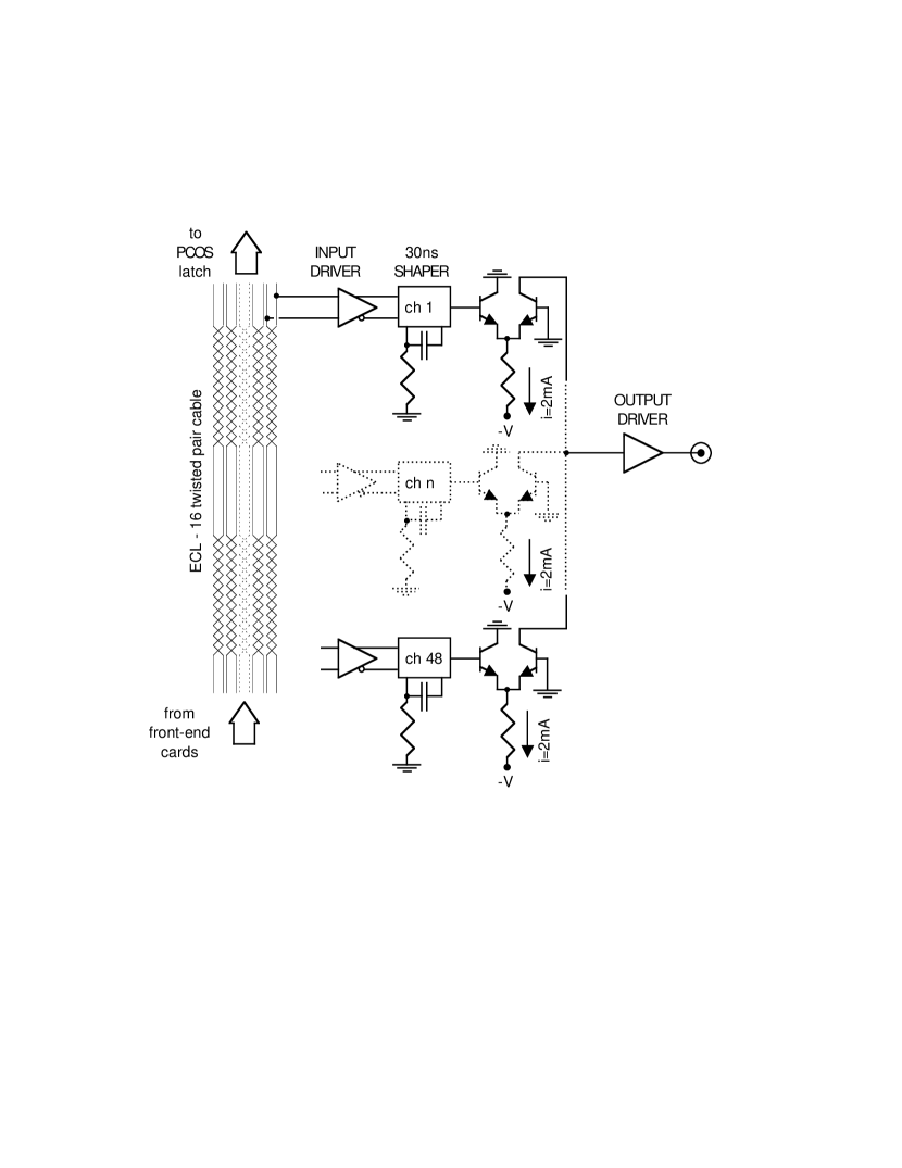
A special version of the module, without the internal shaping circuitry, has been used for the hodoscope signals. The width of the signals in this case is previously adjusted by discriminator modules. In all, twenty-two “Current Adder” modules have been built for the DISTO first level trigger.
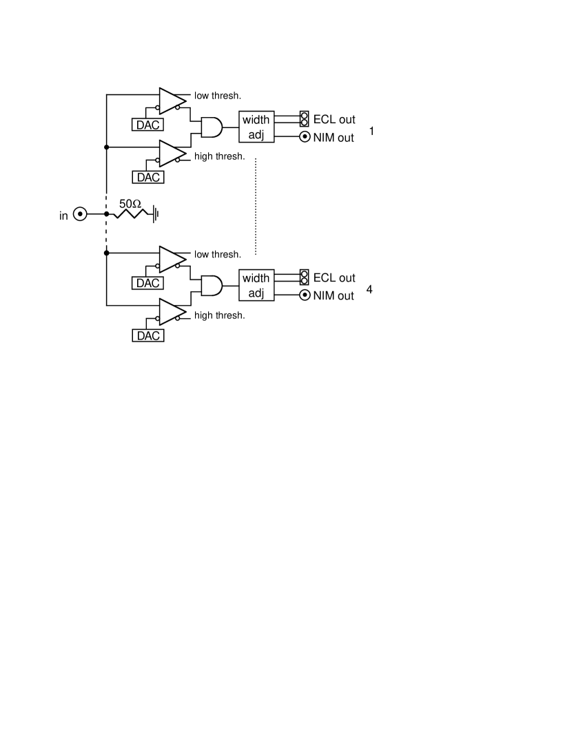
The second module specially designed for the DISTO first level trigger is the “Dual Threshold Discriminator” shown in Fig. 4.
This module was designed to be jointly used with the “Current Adder”. Nevertheless it is a fast, fully programmable discriminator, useful in any experiment. A single input feeds four independent internal sections. Each section is composed of two fast comparators, one AND circuit and a width adjustment. The thresholds of the comparators can be set independently using standard CAMAC functions and can be read back for diagnostic purposes using a multiplexed ADC (not shown in the figure). Every section has two ECL outputs and one NIM output. The input-output delay is 30ns. Twelve DTD modules have been built and installed.
B The 1st Level Trigger Software and Menu-driven Interface
Interface software was written to help the experimenters to program the first level trigger correctly. A minimum knowledge of the implemented first level trigger hardware (Fig. 2) is required. For instance, the multiplicity request per detector is simply given as the number of hits, instead of the digital value of the DAC’s. The internal consistency of the input data is checked and the program rejects inputs when, for example, the value of the high threshold is below the low threshold or an unconnected input is selected.
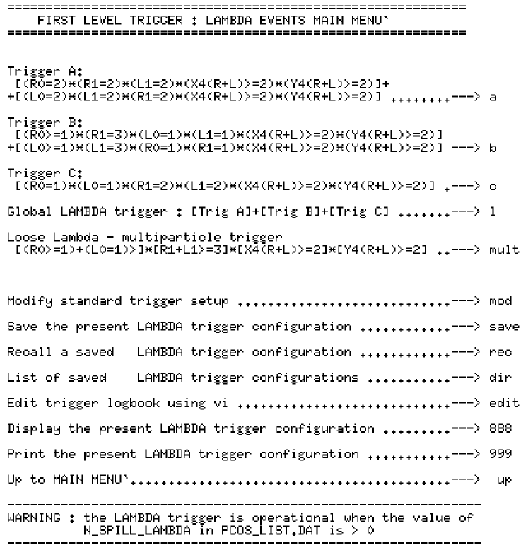
The human interface is menu-driven, with an example menu shown in Fig. 5. The first menu allows selection of specialized sub-menus for the (multi-particle) trigger, the p-p elastic monitor trigger, or diagnostic triggers used during detector tests. The p-p monitor trigger sub-menu is similar to that for the trigger shown in Fig. 5.
The user can select some predefined trigger configurations, can load configurations previously saved, or can modify the present trigger setup. In the last case the user enters into a series of sub-menus where any configuration of DTD’s or LMU’s can be selected. The trigger configuration can be saved and the trigger log-book (a special file recording all modifications of the trigger) is updated.
III Conclusions
A fully programmable trigger circuit has been built for the DISTO experiment at Saturne. Thirty-four new modules specially designed and built for the experiment have been used together with commercial modules. A menu-driven interface was designed to help in programming the trigger hardware.
The programmability and flexibility of the trigger configuration allows us to monitor the experiment using a subset of p-p elastic events, comparing monitoring data, taken under the same experimental conditions as the trigger data, with the vast and well known database available in the literature for p-p elastic scattering.
The trigger performance meets the design specifications for selectivity and rate capability.
IV Acknowledgments
We wish to thank S. Gallian and G. Maniscalco for their contribution to the data acquisition and detector electronics. We are moreover grateful to G. Abbrugiati, G. Giraudo, M. Mucchi, and M. Scalise for their efforts in the design and construction of scintillating fiber detectors. We are particularly indebted to N. Dibiase for essential support since the beginning of the experiment. The continous help of the whole Saturne staff was essential for the success of this work.
References
- [1] J. Arvieux et al., Proposal 213 - Saturne (1991).
- [2] R. Abegg et al., Addendum 281 - Saturne (1993).
- [3] S. E. Vigdor, Flavour and Spin in Hadronic and Electromagnetic Interaction eds. F. Balestra, R. Bertini, and R. Garfagnini (1993) p.317.
- [4] J.Arvieux et al., Int. Symposium on Polarization Phenomena in Nuclear Physics eds. E.J. Stephenson and S.E. Vigdor, AIP Conf. Proceedings No. 339 (1994) p. 476.
- [5] R. Bertini, Nucl. Phys. A585 (1995) 265c.
- [6] A. Maggiora, Nucl. Phys. News Vol.5 No.4 (1995) 23.