![[Uncaptioned image]](/html/hep-ex/9604004/assets/x1.png)
NTU-HEP 96-1
NKNU-HEP 96-1
BELLE Preprint 96-1
KEK Preprint 96-4
NLCTC-HEP 96-1
Measurement of Radiation Damage
on Silica Aerogel Čerenkov Radiator***
submitted to NIM-A.
S.K. Sahua†††Internet address: sahu@kekvax.kek.jp,
M.Z. Wangb, R. Sudac, R. Enomotod,
K.C. Penga,
C.H. Wange,
I. Adachid,
M. Amamif,
Y.H. Changg,
R.S. Guob,
K. Hayashid,
T. Iijimad,
T. Sumiyoshid,
Y. Yoshidah
aNational Taiwan University, Taipei, Taiwan
bNational Kaohsiung Normal University, Kaohsiung, Taiwan
cTokyo Metropolitan University, Tokyo 192-03
dNational Laboratory for High Energy Physics, KEK, Ibaraki 305
eNational Lien Ho College of Tech. and Commerce, Miao Li, Taiwan
fSaga University, Saga 840
gNational Central University, Chung-Li, Taiwan
hToho University, Chiba 274
Abstract
We measured the radiation damage on silica aerogel Čerenkov radiators originally developed for the -factory experiment at KEK. Refractive index of the aerogel samples ranged from 1.012 to 1.028. The samples were irradiated up to 9.8 MRad of equivalent dose. Measurements of transmittance and refractive index were carried out and these samples were found to be radiation hard. Deteriorations in transparency and changes of refractive index were observed to be less than 1.3% and 0.001 at 90% confidence level, respectively. Prospects of using aerogels under high-radiation environment are discussed.
1 Introduction
Silica aerogels(aerogels) are a colloidal form of glass, in which globules of silica are connected in three dimensional networks with siloxan bonds. They are solid, very light, transparent and their refractive index can be controlled in the production process. Many high energy and nuclear physics experiments have used aerogels instead of pressurized gas for their Čerenkov counters [1, 2, 3, 4, 5, 6, 7, 8, 9, 10].
Several experiments in near future operating under very high dose of radiation are likely to employ aerogel Čerenkov counters for their particle identification systems[11, 12, 13, 14]. Stability of aerogels under such circumstances has, however, not been studied yet. In this report we for the first time show the effect of radiation damage on aerogel samples produced by some of us at KEK[11, 13, 14].
In the next section, we quantify the Čerenkov light production in aerogels. Prospects of using aerogels in present and future experiments are explored in the third section. Experimental setup and results are described in fourth and fifth sections, respectively. Conclusion is stated in the sixth section of this report.
2 Silica Aerogels for KEK B-Factory
The production method of aerogels used for the KEK B-factory experiment can be found in Ref. [11, 13, 14]. Accessible range of refractive index () in this method is between 1.006 and 1.060, and it can be controlled to a level of =0.0004. Typical size of a tile was 12cm 12cm 2cm within a tolerance of 0.3%. Absorption and scattering lengths as functions of incident wavelength were obtained from a transmittance measurement with a spectrophotometer[15] using the following relations. We defined a transmission length as;
| (1) |
where T/T0 is transmittance, and is thckness of aerogels. Then we found the absorption and scattering length by fitting with the following equations;
| (2) |
| (3) |
where is absorption length, is scattering length, and a, b are free parameters. The results are shown in Figure 1. At 400 nm, where a typical photo-multiplier tube (PMT) with a bialkali photocathode has maximum sensitivity, the absorption and scattering lengths were measured to be and cm, respectively.
The Čerenkov light yield of our aerogel samples was measured using a 3.5 GeV/c beam at KEK PS ( beam line). Light yield from 12cm-thick aerogel (i.e., 6 layers) was measured by two 3-inch PMTs which were directly attached to both sides of aerogel surfaces. The counter size was 12cm 12 cm 12 cm . Surfaces other than the photocathode area were covered by GORETEX white reflector[16]. Measurements of and , as defined below, are given in Table 1. Number of photoelectrons () is given by Frank-Tamm’s equation[17] :
| (4) |
where is the fine structure constant, thickness of radiator, charge of an incident particle, Čerenkov angle, quantum efficiency of the PMTs, and detection efficiency including light absorption and light collection. Energy-integrated quantum efficiency of PMTs used in this experiment was measured to be
| (5) |
Using Equations 4 and 5, was estimated to be 0.6, which is higher than that for any other existing aerogel counters. The Čerenkov Quality Factor defined as;
| (6) |
for samples of different refractive indices are given in Table 1. For our aerogels, was typically 100cm-1, independent of the refractive index in the range of 1.01 1.03.
3 Use of Aerogels in High-Radiation Environment
3.1 B-Factory
-factories are high luminosity colliders where copious amount of -mesons are produced and their decays are studied [12, 13, 14]. The primary goal of these machines is to study the CP violation in the heavy quark sector [18, 19]. Because of high luminosity of these machines, corresponding detectors are subjected to a substantial amount of radiation from both physics and background events. Particle identification is a vital part of the detectors in these machines. Threshold aerogel Čerenkov counters are being proposed for separation in these detectors.
3.1.1 Collider
Two asymmetric -factories, producing -mesons by annihilating electrons and positrons are being constructed at KEK [13, 14] and SLAC [12]. Threshold aerogel Čerenkov counters are to be used as parts of particle identification system. Radiation dose in these detectors is estimated to be typically 1 kRad/year at places closest to the beam-pipe [14].
3.1.2 Hadron Machine
An imaging Čerenkov counter using aerogel radiator has been proposed [20], which could be a potential candidate for a particle identification system at low angle in a generic hadron -factories, such as the HERA- experiment[21]. Considering the scattering length of our aerogel (Figure 1), aerogel as thin as 1 cm can be used as a radiator to make a ring image of the Čerenkov radiation. In case of the HERA- experiment, the radiation dose is expected to be 10Mrad/year at the innermost edge.
3.2 Nuclear Science
Possibility of separating high energy isotopes by aerogel Čerenkov counters is discussed here. Defining
| (7) |
we obtain
| (8) |
Assuming a Poisson distribution for , the measurement error of is calculated to be
| (9) |
The momentum resolution for a nucleon is expressed as
| (10) |
At a little above the threshold, i.e., , this becomes
| (11) |
Assuming cm-1, =10 cm, and =1.05, we obtain a momentum resolution of 0.07/ which is better than the typical resolution of magnetic spectrometers for high- incident particles i.e., heavy nuclei. Therefore a combination of aerogel counters and a magnetic spectrometer can separate isotopes. The nuclear charge can be measured by some other devices such as scintillator and/or combination of Čerenkov radiators. Rigidity can also be measured by the magnetic spectrometer. Therefore we can determine the mass number of the nucleus (A), using the relationship
| (12) |
For nuclei having the value close to 2, measurement error of A is calculated to be
| (13) |
where is the rigidity resolution of the spectrometer determined by the position resolution and multiple Coulomb scattering. Therefore the limit of separating heavy isotopes is held by spectrometer resolution. For example, with n = 1.05 aerogel and for 5 GeV/nucleon region, we can distinguish nuclei up to Boron with a 0.5%-resolution spectrometer and up to Vanadium with a 0.1%-resolution one.
In summary, using aerogels, we can distinguish nuclear fragments in heavy ion collisions at low angle. Combination of aerogel counters of several refractive indices can even replace a magnetic spectrometer as far as the issue of particle identification goes.
For the RHIC collider, the radiation dose at a very low angle is considered to be less than 100krad/year [22].
3.3 Space Experiments
HEAO-C2 experiment [23], which used aerogel Čerenkov counters, has measured an abundance of heavy nuclei in high energy cosmic rays. Quality of our aerogel is more than four times better than that used in HEAO-C2, thereby showing that if used, it could substantially improve the quality of the data. In addition, a combination of aerogels and a magnetic spectrometer in the experiment could separate the isotopes. This would be a completely new method. The expected radiation dose is 10 kRad/year at 600 km altitude [24].
Recently a space station based experiment – Anti-Matter Spectrometer (AMS) has been proposed[25], which will look for heavy anti-matter nuclei in space. The same technique for isotope separation discussed above can be used to separate isotopes in this spectrometer. The AMS will orbit the earth at about 300 km altitude, where the radiation dose is expected to be several kilorads per year.
4 Experimental Setup
Optical transparency of the aerogel should be as high as possible not to lose Čerenkov photons inside it. The reflactive index of the aerogel (n), should be stable during an experiment. In the present work, two properties of aerogel samples, transmittance and refractive index were measured in order to monitor radiation damage on the samples at the irradiation facility of National Tsing Hua University (Taiwan). In the cases of -factories and space experiments, most of the irradiation is caused by electrons and/or -rays of critical energies. We used a Co60 -ray source, activity of which was 1320 Curie. The error in estimation of radiation dose was dominated by the uncertainty in the placement of the sample (0.3cm) in front of the source and the ambiguity of radius dependent dose. The error at the highest dose value (9.8Mrad of equivalent dose [26]) was the largest, and it was 17%. For each aerogel sample, five or six irradiations were carried out.
4.1 Transmittance
Transmittance of the aerogel samples was measured by observing the ratio of photons absorbed in the aerogel volume with and without the irradiation. A schematic diagram of the setup is given in Figure 2. Three aerogel samples of dimensions 12 cm 12 cm 2 cm each were stacked together in a zinc box. This box was kept inside a mother-box having an LED light box on one side and a photo-multiplier tube on the other. The whole system was enclosed in a big light-tight box. Inner sides of this box were covered with black clothes to absorb any stray light.
We made two such stacks for each refractive index. One was irradiated (RAD-sample) and the other one was kept shielded in the irradiation cell (REF-sample). The latter is for reference. It is important that both RAD and REF be kept under same environmental conditions to cancel out any effects caused by humidity, temperature, dust, or any other factors other than gamma-ray radiation.
The LED (blue in color) was triggered by an external pulse generator to produce bursts of photon. Typically the trigger signal had a pulse height of 3.75 V, width of 420 ns, and was repeated every 10 msec. About 400 photo-electrons were produced for each burst in the absence of aerogel asmples between the LED and the phototube. The number reduced to about 200 p.e. when the stack of aerogel was introduced.
We integrated the charge produced by a 2-inch PMT [27] for each photon burst within a gate of 0.5 sec. Ratio of this integrated charge with aerogel between PMT and LED to that without aerogel gives us a measure of the transparency of that aerogel sample. We will call this ratio as for irradiated sample and for the reference sample. The ratio gives us the transparency of irradiated sample with respect to the reference one. It may be noted that is sensitive only to radiation damage, whereas tells us if there is deterioration such as due to atmospheric conditions. After each stage of irradiation, the RAD and REF samples were tested for transmittance, and the ratios , and were calculated.
Before the irradiation, and were measured several times to make sure that we get a set of systematically consistent consecutive readings. The dominant systematic error came from the uncertainty of placement of aerogel crystals. Other minor sources were temperature dependence and instabilities of PMT and LED. From these readings we found that the combined error of measurement of each transparency ratio, or was 0.55%. Therefore we estimated the error of rabs to be 0.78(=0.55)%.
4.2 Refractive Index
Refractive index of the aerogel sample was monitored using the Prism Formula
| (14) |
where is the refractive index, the angle of the prism, the angle of the minimum deflection.
The setup for measuring is shown in Figure 3. A red laser (Ar II) was shone on the corner of the aerogel sample placed on a rotating table. The aerogel behaved as a prism, and deviated the laser beam on a screen placed at a distance . By rotating the table manually, and checking the minimum distance , angle of the minimum deflection was found out.
A special sample was prepared which was irradiated in parallel with the stacks for transmittance test. Its refractive index was monitored by the method described above after each stage of irradiation.
We estimated the error of refractive index measurement by calculating error propagation of the prism formula. It is estimated as ;
| (15) |
For =1 .012 and 1.028 crystals, the accuracy of measuring was = 0.2 cm and that of was = 0.1 cm. For = 1.018 samples, however, the was worse (=0.3 cm) due to the inferior surface quality, giving rise to a spread of the laser spot on the screen. Error in measuring the refracting angle of the sample was = . The errors were then calculated to be 0.00035 for = 1.012 and 1.028 samples, and 0.001 for = 1.018 sample, using Equation 15. It may be noted that dominates the final error.
5 Results
5.1 Transmittance
Samples of three refractive indices : 1.012, 1.018 and 1.028 were tested. The transparency ratio was measured at several points, ranging from 1 kRad to 9.8 MRad. The results are plotted in Figure 4 for each reflactive index.
No degradation in transparency is observed in any samples within experimental errors. Defining absolute deterioration as the maximum of the measurement error and the deviation from the initial measurement, we conclude that the radiation damage to transparency of the samples is less than 1.3% at 90% confidence level (CL) at 9.8 Mrad dose.
5.2 Refractive Index
Samples of three refractive indices : 1.012, 1.018 and 1.028 were tested. Refractive index was measured at several points, ranging from 1 kRad to 9.8 MRad. The results are shown in Figure 5.
Angle for the aerogel samples was . Typical values of and were 160 cm and 6 cm, respectively. Accuracy of determining refractive index () in this method is better than 0.001.
Again, we do not see any change in refractive index in any of the samples within experimental errors [28].
5.3 Post-irradiation Beam Test
The three irradiated samples were later tested with the pion beam at the beam line of the KEK-PS. Momentum of the beam was varied between 0.8 GeV/c and 3.5 GeV/c, from which refractive indices of the samples could be calculted. The numbers perfectly agreed with the values obtained at the production time (the open symbols in Figure 5). This gives us additional confirmation that there has not been any radiation damage to the aerogel samples. Using the same definition of deterioration as above, we conclude that the radiation damage to refractive index of the samples is less than 0.001 at 90% CL at 9.8 MRad dose.
6 Conclusion
Silica aerogels of low refractive index () are found to be radiation-hard at least up to 9.8 Mrad of gamma-ray radiation. We observe no change in transparency and refractive index within the error of measurement after the irradiation. Measurement accuracies were 0.8% for transparency and 0.0006 for refractive index, respectively. 90%-CL upper limits on the radiation damage are 1.3% for transparency and 0.001 for refractive index, respectively.
Silica aerogels can be used in high-radiation environments, such as -factories, nuclear and heavy-ion experiments, space-station and satellite experiments, without any fear of radiation damage.
Acknowledgements
We would like to thank the BELLE Collaboration of KEK -Factory for its help in this project. The aerogels were developed under a collaborative research program between Matsushita Electric Works Ltd. and KEK. One of the authors (RE) appreciates Drs. S. Kuramata (Hirosaki Univ.) and S. Yanagida (Ibaraki Univ.) for useful discussions on certain relevant physics issues. We are grateful to the staff-members Dr. F.I. Chou, M.T. Duo, K.W. Fang and Y.Y. Wei of the Radio-isotope Division of NSTDC at National Tsing Hua University, Hsin-Chu (Taiwan), where the irradiation was conducted, for their help and co-operation. We are thankful to Prof. J.C. Peng of LANL for valuable comments on this manuscript. This experiment was supported in part by the grant NSC 85-2112-M-002-034 of the Republic of China.
References
- [1] D.E. Fields et al., Nucl. Instrum. Meth. A349 (1994) 431.
- [2] C. Lippert et al., Nucl. Instrum. Meth. A333 (1993) 413.
- [3] T. Hasegawa et al., Nucl. Instrum. Meth. A342 (1994) 383.
- [4] P. Vincent et al., Nucl. Instrum. Meth. A272 (1988) 660.
- [5] K. Maurer et al., Nucl. Instrum. Meth. A224 (1984) 110.
- [6] G. Poelz, Nucl. Instrum. Meth. A248 (1986) 118.
- [7] P. J. Carlson et al., Nucl. Instrum. Meth. A192 (1982) 209.
- [8] H. Burkhardt et al., Nucl. Instrum. Meth. A184 (1981) 319.
- [9] C. Arnault et al., Nucl. Instrum. Meth. A177 (1980) 337.
- [10] J. P. De Brion et al., Nucl. Instrum. Meth. A179 (1981) 61.
- [11] I.Adachi et al., Nucl. Instrum. Meth. A355 (1995) 390.
- [12] BABAR Colloboration, “BABAR: Technical Design Report”, SLAC-R-95-457.
- [13] Belle collaboration, “Letter of Intent for the Belle Collaboration”, KEK Report 94-2.
- [14] Belle collaboration, “Technical Design Report”, KEK Proceedings 95-1.
- [15] Hitachi Co Ltd. model U-3210.
- [16] Japan Goretex Co Ltd. Spec. No. 116-027.
- [17] “Review of Particle Properties”,Phys. Rev. D50 (1994) 1173
- [18] M.Kobayashi and T.Maskawa, Prog. Theor. Phys. 49 (1973) 652.
- [19] A.Carter and A.I.Sanda, Phys. Rev. Lett. 45 (1980) 952.
- [20] T. Ypsilantis and J. Seguinot, “RICH Outlook”, to be appeared in Proceedings of the Second Workshop on Ring Imaging Čerenkov Detectors, Upsalla, Sweden, June 12-16, 1995.
- [21] T.Lohse et al., “HERA B: An experiment to study CP violation in the B system using an internal target at the HERA proton ring: Proposal”, DESY PRC 94-02.
- [22] Private communication with B.Jacak and R.S.Hayano.
- [23] J.J.Engelmann et al., Astron. Astrophys. 233 (1990) 96.
- [24] Private communication with T.Takahashi.
- [25] S.C.C. Ting et al., “Antimatter Spectrometer in Space”, Study of Feasibility, 1994
- [26] We define the equivalent dose as the amount of dose that would have been absorbed if the sample stopped all the -rays going through it. Absolute dose absorbed by aerogel, being a very light material, is much smaller than the equivalent dose.
- [27] Hamamatsu Photonics K.K., R329-05S.
- [28] The large fluctuation of measurements for the n=1.020 sample is due to its surface roughness, which changes the effective prism angle .
Table 1, S.K.Sahu et al., NIM-A
| (cm-1) | ||
|---|---|---|
| 1.010 | 25.7 | 109 |
| 1.015 | 37.3 | 106 |
| 1.020 | 45.7 | 95 |
Figure 1, S.K.Sahu et al., NIM-A

Figure 2, S.K.Sahu et al., NIM-A
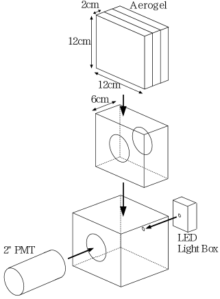
Figure 3, S.K.Sahu et al., NIM-A
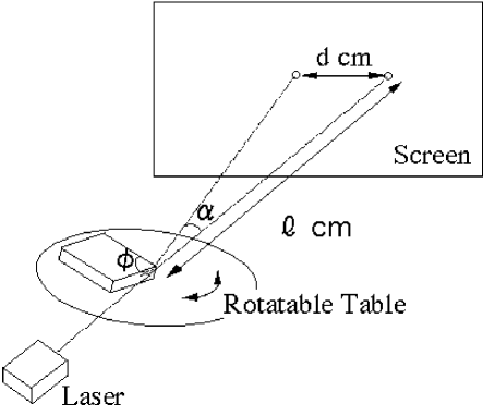
Figure 4, S.K.Sahu et al., NIM-A

Figure 5, S.K.Sahu et al., NIM-A
