THE RING IMAGING DETECTOR FOR CLEO III
Marina Artuso
Department of Physics, Syracuse University, Syracuse, NY 13244
ABSTRACT
The CLEO detector will undergo major improvements in conjunction with a high luminosity upgrade of the CESR electron positron collider, that should increase the luminosity of this machine by a factor of 10. The most innovative feature of the planned CLEO detector is the addition of a state of the art particle identification system, based on a proximity focused Ring Imaging Cherenkov detector. The goal is to achieve good hadron identification at all the momenta relevant to the study of decays of B mesons produced at the resonance. This detector design will be discussed, including details of the mechanical design and the readout electronics. The performance of a prototype module will be described.
1. Introduction
A major upgrade of the CLEO detector is underway (CLEO III), which, together with the planned increase in luminosity of the CESR collider at Cornell University, should open exciting prospects for studying CP violation in charged decays and mapping the phenomenology of rare decays. The main innovation is the introduction of a high class particle identification system which will distinguish charged hadrons in the kinematics domain characteristic of decays at the with high efficiency and low fake rate. The approach chosen is a Ring Imaging Cherenkov detector (RICH), where the position of the Cherenkov photons generated by relativistic particles crossing a dense medium is reconstructed at a detector plane.
The CLEO RICH is based on the proximity focusing approach, in which the Cherenkov cone is simply let to expand in a volume filled with inert gas (the expansion gap) as much as allowed by other spatial constraints, before intersecting the detector surface where the coordinates of the Cherenkov photons are reconstructed. In our approach the radiator is a crystal (LiF). The photon detection is performed in a thin gap multiwire proportional chamber (MWPC) with cathode pad readout. The photoconverter chosen is triethylamine (TEA), whose molecules are dispersed in the gas of the photodetector. A fine segmentation of the cathode pad is required in order to achieve the spatial resolution needed, which in turn implies a high density of readout electronics. Our design involves 230,000 cathode pads. The availability of a suitable VLSI front end analog processor is therefore a key element in this detector.
The goal of having excellent separation power between hadron from decays, most notably ’s and ’s from 2-body rare decay modes, determines the requirements on the angular resolution per track. We define the separation in terms of the number of standard deviations defined as the ratio between the difference and the average error on the Cherenkov angle measurement for each track, . Our design goal is =4 for all the momenta of interest. In our case the minimum angular separation between these two particle species is 12.8 mr, corresponding to the maximum momentum of 2.8 GeV/c at the . We consider a mean number of 10 detected photoelectrons as the minimum acceptable value.
2. A novel radiator geometry
In order to improve both the angular resolution per track and the number of reconstructed photoelectrons a novel radiator geometry has been proposed [1], and is presently undergoing a technical feasibility study. It involves cutting the outer surface of the radiator with a profile resembling the teeth of a saw, and therefore it is referred to as ’sawtooth radiator’. The major advantage of this configuration is that it reduces the losses of photons due to total internal reflection at the interface between the radiator and the expansion gap. A detailed simulation has shown that a tooth angle of 45∘ is close to optimal. Fig. 1 summarizes the results of this study, which focuses on particles with GeV/c. The mean number of reconstructed photoelectrons , Cherenkov angle resolution per track and the probability for a to fake a are plotted as a function of the angle between the charged particle and the normal to the radiator inner surface. Besides featuring an improved performance, this solution has the advantage of not requiring tilted radiator segments in the region around , in order to prevent all the Cherenkov photons from being trapped inside the radiator because of total internal reflection.
3. Mechanical design
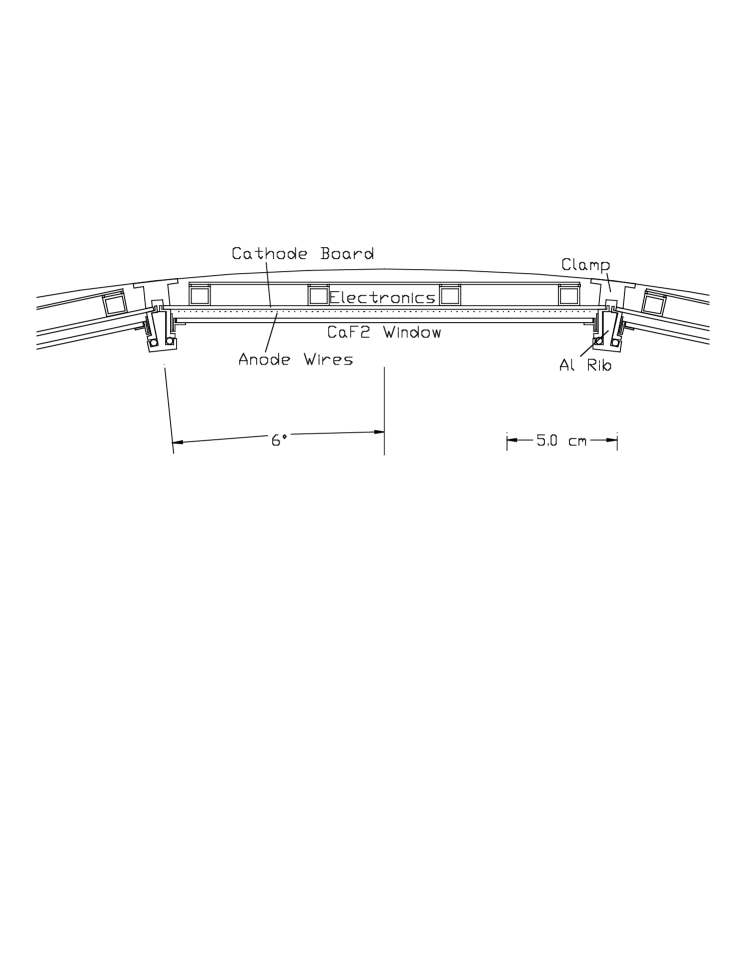
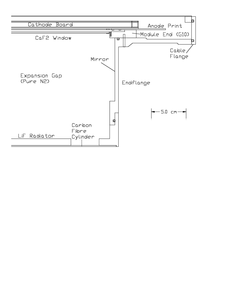
The mechanical design of this detector faces several challenges. One of the most severe constrains is dictated by the bandwidth of the photosensitive element, centered around 150 nm. This implies a hermetic sealing of the expansion gap from the neighboring gas volumes, in order to prevent contamination from oxygen and water from the outside environment. In addition the TEA inside the photodetector must not leak into the expansion gap because this would also cause loss of photoelectrons. The other important goal is to keep the windows free of any kind of mechanical stress in order to prevent cracks from developing. This has been achieved by attaching these windows to their frames through hinges, as shown in Fig. 2, which provide a soft joint to relieve the stresses. The LiF radiators are held in place by an inner carbon fiber cylinder to which they are attached. Individual photosensitive detectors will be held in place by a support frame attached to the inner cylinder, as shown in Fig. 3. In addition, the back of the cathode boards which constitute the outer side of the MWPC are strengthened by hollow G10 rods which also act as channels for the cooling gas (). The strength has been achieved with great care to minimize the amount of material in the detector, in order to preserve the excellent performance of the electromagnetic CsI calorimeter. The average material thickness is 13% of a radiation length for tracks at normal incidence.
In order to improve the coupling between cathode pads and anode wires and to reduce the mean number of pads corresponding to a single photoelectron avalanche, the chamber geometry is asymmetric, with the wire to cathode pad distance of 1 mm and an overall gap thickness of 4 mm. The wires run along the 2.5 meter detector length. In order to preserve a high uniformity in the wire to cathode distance over such a length ceramic spacers are glued between the wires and the cathode pads along the azimuthal direction every 30 cm.
4. Readout Electronics
The 230,000 readout channels are distributed over the surface at the outer radius of the detector and are impossible to access routinely. Therefore the readout architecture must feature high parallelism, and extensive testing of active components and connection elements is required in order to insure their reliability. The MWPC detector surface is segmented into 30 modules, which will be divided into 12 subunits each with 640 readout channels. Each of these subunits will communicate via a low mass cable connection with VME cards providing the control signals and receiving the analog or digitized signals as discussed below.
Several considerations affect the design of the individual channel processor. Low noise is an essential feature because the charge probability distribution for the avalanche produced by a single photon is exponential at moderate gains. It should be stressed that it is beneficial to run at low gains to improve the stability of chamber operation. Therefore in order to achieve high efficiency, the noise threshold should be as low as possible. An equivalent noise charge of about 200 electrons is adequate for our purposes. On the other hand, an exponential distribution implies that a high dynamic range is desirable in order to preserve the spatial resolution allowed by charge weighting. Note that charged particles are expected to generate pulses at least 20 times higher than the single photon mean pulse height. In order to improve the robustness of the readout electronics against sparking, a protection circuit constituted by a series resistor and two reverse biased diodes is required in the input stage. Finally it is important to sparsify the information as soon as possible in the processing chain, as the occupancy of this detector is very low and therefore only a small fraction of the readout channels contain useful signals.
There is a preamplifier/shaper VLSI chip developed for solid state detector applications which incorporates many of the features discussed above [2]. A dedicated version of this chip, called VA_RICH, has been developed and will be tested shortly. Its predicted equivalent noise charge is given by:
| (1) |
The first term corresponds to the noise contribution from the input transistor and the (80 ) series resistor used for the input protection and the second to the noise from subsequent stages, small but non negligible because of the lower gain chosen to increase the dynamic range. This device is expected to maintain linear response up to an input charge of 700,000 .
The choice of digitization and sparsification technique has not yet been finalized. Under consideration is the digitization and sparsification at the front end level, using the zero suppression scheme and the ADC included in the SVX II readout chip [3]. Alternatively we will digitize all the analog output signal and perform the zero suppression afterwards.
5. Performance of the CLEO RICH Prototype
Our first step in the R&D effort towards the construction of this detector has been the construction of a prototype whose length is about 1/3 of an individual detector module in the final design and whose width is about the same. The prototype system is enclosed in a leak tight aluminum box. The expansion gap is 15.7 cm. In this prototype we use plane LiF radiators. The chamber geometry is approximately the same as the final design in terms of gap size, wire to cathodes distance and pad sizes. The total number of pads read out is 2014. Pad signals are processed by VA2 [4] preamplifier and shapers. The detector plane is divided into 4 quadrants each of which has 8 VA2 daisy–chained for serial readout.
This prototype has been installed in a cosmic ray set up composed of a telescope of scintillators whose geometrical arrangement can be varied. We either trigger on energetic cosmic rays having their Cherenkov image within the acceptance of the photodetector but not the charged track, or we trigger on charged tracks going through the detector.
Fig. 4 shows the charge distribution of reconstructed photon clusters as a function of the anode wire voltage for several different voltages when the gas mixture is . Note that the pulse height distribution is consistent with an exponential profile and its mean value increases with , as expected. Fig. 5 shows the excitation curve measured for the same gas mixture. It can be seen that the plateau corresponds to . This number has to be corrected for possible background hits, which we estimate to be about 1 per event. On the other hand there are subtle effects related to the fact that clusters associated with different photoelectrons are often close in space and therefore have a finite chance of overlapping into a single cluster, thus reducing the reconstructed . So far we believe that we are loosing on average one photoelectron per event due to this effect and that some improvement can be achieved in the future. This performance is in close agreement with our expectations based on the performance of a similar prototype built and tested by the College de France–Strasbourg group [5]. A tracking system is being added to this set–up to allow us to measure also the angular resolution of our device.
6. Acknowlegements
We would like to thank the A. Efimov, M. Gao, S. Kopp, R. Mountain, Y. Mukhin, S. Playfer, and S. Stone for for useful discussion. Special thanks are due to E. Nygard for low noise electronics and all the team of IDE AS for developing the VA_RICH chip optimized for our application.
REFERENCES
-
[1] A. Efimov et al., Syracuse Un. Preprint, HEPSY-94-8 (1994) to be published in Nucl. Instr. and Meth. A
-
[2] E. Nygard et al., Nucl. Instr. and Meth. A301 (1991) 506.
-
[3] O. Milgrome Talk given at the 2nd International Meeting on Front End Electronics for Tracking Detectors at Future High Luminosity Colliders Perugia, Italy (1994).
-
[4] O. Toker et al., CERN Preprint CERN–PPE/93–141 (1993).
-
[5] J.L. Guyonnet et al., Nucl. Instr. and Meth. A343 (1994) 178.
Figure Captions
Fig. 1 Performance of sawtooth radiator (curves are parametrized by the sawtooth angle): 1.a) The average number of detected photoelectrons as a function of the incident track angle, 1.b)The angular resolution per track as a function of incident track angle, 1.c) The probability for a 2.8 GeV/c to fake a for 95% efficiency.
Fig. 2 A detail of a section of the CLEO RICH showing the mechanical design of individual detector modules showing the attachment method for the window and the method to strengthen the cathode plane.
Fig. 3 A detail of a section of the CLEO RICH showing the attachment of the support structure for the detector modules to the inner cylinder.
Fig.4: Photon induced avalanche charge distribution at different anode voltages. The voltage on the metallization of the windows is kept at -1350V.
Fig. 5: Excitation curve for . The voltage on the metallization of the windows is kept at -1350V.