HEPSY 95-2Sept., 1995
CLEO III, A Dectector To Measure Rare Decays
and CP Violation
Sheldon Stone111Stone@suhep.phy.syr.edu
Physics Dept., Syracuse Univ., Syracuse, NY, 13244-1130
Abstract
The symmetric collider CESR is undergoing a series of upgrades
allowing for luminosities in excess of cm-2s-1.
The most important goals of the upgrade are precision measurement of standard
model parameters , , , , and
searching for CP
violation and standard model violations in rare decays. A new detector
upgrade, called CLEO III, has started which includes a new silicon-wire
drift chamber tracking system and a Ring Imaging Cherenkov Detector, RICH,
using a LiF radiator and CH4-TEA gas based photon detector.
..
Presented at BEAUTY ’95 - 3nd International Workshop on B-Physics at Hadron Machines Oxford, UK, 10-14 July, 1995
1 Introduction - Physics Goals
The CLEO collaboration is in the midst of a detector upgrade, to match the CESR increase in luminosity to cm-2s-1 and to insure meeting the physics goals described below.
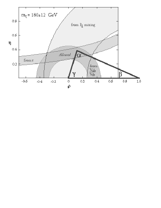
The current extent of knowledge on weak mixing in the quark sector can be shown by plotting constraints in the and plane given by measurements of the parameter describing CP violation in decay, and by mixing and semileptonic decays. An analysis of the allowed parameter space is shown in Figure 1 [1]. Overlaid on the figure is a triangle that results from the requirement , i.e. that the CKM matrix be unitary. Measurements of CP violation in decays can, in principle, determine each of the angles , and of this triangle independently.
There are many measurements to make with CLEO III. Here I will only mention a few of the most important.
-
•
The dominant error in the band is caused by the uncertainty in . This can be improved, for example, by measuring the rate for at maximum four-momentum transfer.
-
•
The error in the band can be decreased by using exclusive semileptonic decays such as [2].
-
•
The error on the mixing band comes dominately from the lack of knowledge of . We can reduce this uncertainty by comparing models with our measurement of currently () MeV [3].
-
•
The ratio may be ascertained by measuring the ratio of the branching ratios [4]. The basic idea here is that the difference in the two final states comes mainly from having in the case of and for . Although it has been argued that other diagrams may contribute to the numerator this would lead to the inequality of and and would therefore be a measurement of direct CP violation. It is also likely that these other diagrams would induce an inequality between neutral and charged final states. In short, this is a very interesting physics area.
-
•
Measure CP violation. We will try and measure the CP violation angle using one of two techniques. The first, suggested by Gronau and London, involves measuring the rates for , and , and the corresponding rates for decay. ( indicates that the decays into a CP eigenstate, for example .) The second involves measuring a rates for two-body pseudoscalar decays and etc…[4]. Other attempts to measure CP violation through rate asymmetries such as differences between and or even to measure the angle by using the standard mode and the small motion in our symmetric collider.
2 CESR upgrades
CESR has achieved the highest instantaneous luminosity of any collider, cm-2s-1. However, heavy quark physics is limited by the number of events, so even higher luminosities are desired. The approved CESR upgrade will have luminosity in the range of 2. This is accomplished in two stages. In the first stage there will be 9 “trains” of 3 bunches, and a small horizontal crossing angle, with a goal of . This phase is being implemented now. The second stage has 9 trains of 5 bunches, a larger horizontal crossing angle, a smaller (1 cm) requiring a new interaction region and therefore a new inner detector, and superconducting RF cavities.
There is also a future plan being developed, to reach luminosity in excess of by using 180 bunches, round beams in the interaction region and a reduced bunch length. This plan would use the same inner detector being built now, which is the subject of the rest of this article.
3 The CLEO III Dectector Upgrade
The CLEO II goal was to reconstruct thousands of mesons using excellent tracking and photon detection and modest particle identification. Although the CLEO II goals have been met, experience with the detector and the desire to meet new physics goals, have uncovered several serious deficiencies. These include the rather thick drift chamber endplate and associated material which seriously compromises photon detection in the endcaps and outer barrel region, and the lack of good quality charged hadron identification222The Drift Chamber dE/dx system does provide separation above 2.3 GeV/c.above 750 MeV/c. Furthermore, the electronics and DAQ system will not support the higher interaction rates caused by the increased luminosity. Finally, the inner tracking detector must be replaced because part of the space is necessary for the final focus quadrupoles.
There are several advantages to the detector being upgraded since CESR is a symmetric energy accelerator. It is easier to have a large solid angle coverage than in an asymmetric machine, since less of the phase space goes down the beam pipe. The maximum momentum of a decay product is 2.8 GeV/c, rather than about 4 GeV/c for an asymmetric machine operating at the . It is also important that we can build upon our existing detector utilizing some of the more expensive parts such as the CsI calorimeter, the magnet and the muon system, all of which have functioned excellently.
The design philosphy of CLEO I was to have excellent tracking and charged particle momentum resolution. Advances in crystal growth techniques, superconducting magnet technology and electronics made it possible to add excellent photon and electron detection in CLEO II [5]. The design philosophy of CLEO III is to maintain the excellent charged particle resolution while sacrificing 20 cm of space for charged particle identification. This is possible because we can add a high precision silicon detector near the beam pipe which can precisely determine angles and then have a low mass drift chamber which can precisely measure transverse momentum. It is important to realize that multiple scattering is the largest source of tracking errors over the entire range of decay momenta at CESR.
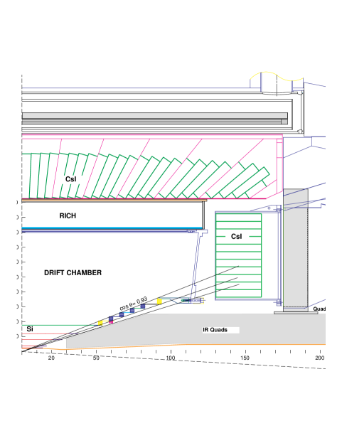
An overview of CLEO III is shown in Fig. 2. There is a four layer silicon detector, followed by a drift chamber with staggered inner section to accommodate the CESR final focus quadrupoles. Radially beyond this is 20 cm space for the barrel particle identification detector. At the ends of the detector are relocated and repackaged CsI calorimeter endcaps with improved performance and provision for mounting the drift chamber and CESR machine components.
4 The RICH system
4.1 Introduction
Ring imaging Cherenkov detectors (RICH) are capable of providing excellent identification of charged particles. Several systems have been implemented in hadron beams and collider experiments [6].
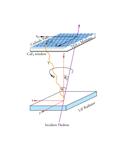
The CLEO RICH is based on the ‘proximity focusing’ approach, in which the Cherenkov cone is simply let to expand in a volume filled with ultraviolet transparent gas (the expansion gap) as much as allowed by other spatial constraints, before intersecting the detector surface where the coordinates of the Cherenkov photons are reconstructed. The components of our system are illustrated in Fig. 3. It consists of a LiF radiator, providing U.V. photons, an expansion region, and a photosensitive detector made from a wire proportional chamber containing a CH4-TEA gas mixture. The cathode plane is segmented into pads to reconstruct the photon positions.
The design is based on work of the College de France–Strasbourg group,[7]. We are considering a unique geometry for the LiF solid radiator [8], where the light emitting surface is shaped like the edge of a saw blade with the teeth angled at 45o. If we can manufacture this shape it will produce more photons and achieve better resolution. A fine segmentation of the cathode pad ( 7.5x8mm2) is required in order to achieve the spatial resolution needed, which in turn implies a high density of readout electronics.
The angular resolution per detected photon is comprised of several sources. The most important are the chromatic error, which results from the variation of the index of refraction with the wavelength, the emission point error, which results from the lack of knowledge about where the photon is emitted, and the position error in detecting the photon. There is also a small error caused by the inability to resolve some of the overlapping photon cluster. The individual sources of error have been determined by using GEANT. The combined resolution is about 13.5-14 mrad resolution per detected photon independent of the track incident angle. This corresponds to a 3.7 mrad resolution per track. Since the difference in Cherenkov angle between pions and kaons is 12.8 mr at 2.8 GeV/c we expect this system to have at least 3.5 standard deviation separation. However, should it be possible to obtain the sawtooth radiators, the separation will be much better [8].
The device will be constructed with a 30 fold segmentation. The LiF radiators are held in place by an inner carbon fiber cylinder to which they are attached. The back of the cathode boards which constitute the outer side of the MWPC are strengthened by hollow G10 rods which also act as channels for the cooling gas (). The strength has been achieved with great care to minimize the amount of material in the detector, in order to preserve the excellent performance of the electromagnetic CsI calorimeter. The average material thickness is 13% of a radiation length for tracks at normal incidence.
4.2 Readout Electronics
The 230,000 readout channels are distributed over the surface at the outer radius of the detector and are impossible to access routinely. Therefore the readout architecture must feature high parallelism, and extensive testing of active components and connection elements is required in order to insure their reliability. The MWPC detector surface is segmented into 30 modules, which will be divided into 12 subunits each with 640 readout channels. Each of these subunits will communicate via a low mass cable connection with VME cards providing the control signals and receiving the analog or digitized signals as discussed below.
Several considerations affect the design of the individual channel processor. Low noise is an essential feature because the charge probability distribution for the avalanche produced by a single photon is exponential at moderate gains. It should be stressed that it is beneficial to run at low gains to improve the stability of chamber operation. Therefore in order to achieve high efficiency, the noise threshold should be as low as possible. An equivalent noise charge of about 200 electrons is adequate for our purposes. On the other hand, an exponential distribution implies that a high dynamic range is desirable in order to preserve the spatial resolution allowed by charge weighting. Note that charged particles are expected to generate pulses at least 20 times higher than the single photon mean pulse height. In order to improve the robustness of the readout electronics against sparking, a protection circuit constituted by a series resistor and two reverse biased diodes is required in the input stage. Finally it is important to sparsify the information as soon as possible in the processing chain, as the occupancy of this detector is very low and therefore only a small fraction of the readout channels contain useful signals.
There is a preamplifier/shaper VLSI chip developed for solid state detector applications which incorporates many of the features discussed above [2]. A dedicated version of this chip, called VA_RICH, has been developed and will be tested shortly. Its predicted equivalent noise charge is given by:
| (1) |
where is the input capacitance of 2 pf. The first term corresponds to the noise contribution from the input transistor and the (80 ) series resistor used for the input protection and the second to the noise from subsequent stages, small but non negligible because of the lower gain chosen to increase the dynamic range. This device is expected to maintain linear response up to an input charge of 700,000 .
The choice of digitization and sparsification technique has not yet been finalized. Under consideration is the digitization and sparsification at the front end level, using the zero suppression scheme and the ADC included in the SVX II readout chip [10]. Alternatively we will digitize all the analog output signal and perform the zero suppression afterwards.
4.3 Results from Prototype
We have constructed a prototype of an individual detector module about 1/3 the length of an actual detector module and about the same width. The prototype system is enclosed in a leak tight aluminum box. The expansion gap is 15.7 cm. In this prototype we have used plane 1 cm thick LiF radiators. The chamber geometry is approximately the same as the final design in terms of gap size, wire to cathodes distance and pad sizes. The total number of pads read out is 2016. Pad signals are processed by VA2 preamplifier and shapers [9]. The detector plane is divided into 4 quadrants each of which has 8 VA2 daisy–chained for serial readout.

This prototype has been exposed to hardened cosmic rays. Fig. 4 shows the charge distribution of reconstructed photon clusters as a function of the anode wire voltage for several different voltages. Note that the pulse height distribution is consistent with an exponential profile and its mean value increases with , as expected. Fig. 5 shows the excitation curve for hits which are more than six standard deviations above noise. It can be seen that the plateau corresponds to . This number has to be corrected for possible background hits, which we estimate to be about 1 per event. This performance is in close agreement with our expectations based on the performance of a similar prototype built and tested by the College de France–Strasbourg group [7]. A tracking system is being added to this set–up to allow us to start measuring Cherenkov angular resolutions.

5 Silicon vertex detector/tracker
In order to provided good measurements of angles and precise vertex positions, useful especially for charm decays, we are constructing a four layer double sided silicon device, which covers 93% of 4. Our concept is to use only one detector size with 50 m strip pitch and external dimension of 2.7cm5.26cm300m.
The number of detectors and their properties are listed in Table 1. The large amount of capacitance on the fourth layer makes it difficult to achieve low noise performance. The noise target is 125 + 8/pf in a radiation hard version of the chip. The rad-hard version of the Viking chip, VH1, gives 400 + 5/pf, which is almost good enough. The silicon group is pursuing making their own front end preamplifier.
| Layer# | r(cm) | # in | # in z | total # | C(pf) |
|---|---|---|---|---|---|
| 1 | 2.4 | 7 | 4 | 28 | 12 |
| 2 | 3.8 | 10 | 4 | 40 | 19 |
| 3 | 7.5 | 20 | 8 | 160 | 38 |
| 4 | 12.0 | 30 | 12 | 360 | 60 |
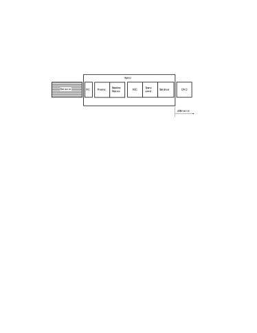
The silicon electronic system is being developed along the same lines as the RICH electronics mentioned above. A possible system is outlined in Fig. 6.
6 Drift Chamber
In order to reduce multiple scattering which limits the tracking resolution, material in the chamber and the chamber walls is being reduced as much as possible. To help photon detection, the endplate is being constructed out of 1.5 cm thick shaped aluminum. To fit around the interaction region quadrupoles, there is an inner conical section which contains only axial wire layers and an outer cylindrical section which contains alternating stereo wire layers (see Fig. 2).
A Helium based gases will be used in the chamber. Properties of some of these gases are shown in Table 2 along with the “standard”, 50% Ar-50% CH4 mixture. Here is the radiation length, the Lorentz angle, #e/cm the number of ion pairs produced per cm, the resolution in the specific ionization measurement and , the ratio of specific ionization between electrons and pions at minimum loss. (The latter two quantities are from calculations.)
| Gas mixture | #e/cm | ||||
|---|---|---|---|---|---|
| Ar-C2H6 (50:50) | 178 | 68.9 | 33.8 | 6.3% | 1.46 |
| He-C3H8 (60:40) | 569 | 35.0 | 32.6 | 6.3% | 1.30 |
| He-C3H8 (40:60) | 392 | 38.6 | 45.8 | 5.7% | 1.28 |
| He-C4H (70:30) | 564 | 30.3 | 31.1 | 6.3% | 1.29 |
| He-C2H6 (50:50) | 686 | 41.4 | 24.8 | 6.7% | 1.32 |
We have found spatial resolutions in test chambers of better than 100 m for most of the He based mixures, even when the test chambers have been placed in a 1.5T magnetic field. These resolutions are better than achieved in Ar-C2H6 in the same test setup. In Fig. 7 we show the hit efficiency for different gases as function of the incident track position across the drift cell. The efficiency is much better using the He based gases due to the smaller Lorentz angle. These gases are so promising that CLEO II will immeadiately adopt one of the He mixtures.

7 Acknowledgements
This work reported here is supported by the National Science Foundation. I thank M. Artuso, C. Bebek, H. Kagan and the RICH group at Syracuse Univ. for their help.
References
- [1] S. Stone, “Fundamental Constants from and Decay,” HEPSY 94-5, in Proceedings of “Particle Strings and Cosmology,” meeting, Syracuse, NY (1994), ed. K. Wali, World Scientific, Singapore (1995) and in “Proceedings of DPF94 Meeting,” Albuquerque, NM (1994) ed. S. Seidel, World Scientific, Singapore (1995).
- [2] R. Ammar et al., “Measurement of the Branching Ratios for exclusive Decays,” CLEO CONF 95/9, EPS0165 (1995).
- [3] D. Gibaut et al., “Measurement of ,” CLEO CONF 95-22, EPS0184 (1995).
- [4] S. Playfer and S. Stone, “Rare Decays”, HEPSY 95-01 (1995), to be published in Int. Journal of Mod. Phys. A.
- [5] Y. Kubota et al., Nucl. Instr. and Meth. A301, A320 (1992) 56.
- [6] J. Seguinot and T. Ypsilantis, Nucl. Instru. & Meth.A343, 1 (1994).
- [7] J.L. Guyonnet et al., Nucl. Instr. & Meth. A343 (1994) 178.
- [8] A. Efimov et al. , “Monte Carlo Studies of a Novel LiF Radiator for RICH Detectors,” HEPSY 94-8 (1994), to be published in Nucl. Instr. & Meth.; M. Artuso, “The Ring Imaging Cherenkov Counter for CLEO III,” presented at 6th Int. Symp. on Heavy Flavour Physics Pisa, Italy, June 1995, to appear in proceedings.
- [9] E. Nygard et al., Nucl. Instr. and Meth. A301 (1991) 506.
- [10] O. Milgrome Talk given ath the 2nd International Meeting on Front End Electronics for Tracking Detectors at Future High Luminosity Colliders Perugia, Italy (1994); R. Yarema, “A Beginners Guide to the SVXII,” FERMILAB-TM-1892 (1994).