The erenkov Correlated Timing Detector:
Materials, Geometry and Timing Constraints
Abstract
The key parameters of erenkov Correlated Timing (CCT) detectors are
discussed. Measurements of radiator geometry, optical properties of
radiator and coupling materials, and photon
detector timing performance are presented.
1 Introduction:
The CCT concept has been outlined in a previous publication [1] and described in detail in an internal CLEO collaboration document[2]. The technique uses the correlation between photon pathlength and erenkov production angle to infer this angle by measuring the time taken for the totally internally reflected erenkov photons to “bounce” to the end of the radiator. The most typical radiator geometry is that of a quartz bar having rectangular cross-section, typically a few centimeters on a side, and having a length of about a meter. This is very similar to the radiators in the DIRC design of Ratcliff[4]. The key parameters of a CCT system will all be related to timing performance. In practical terms this translates to photo detector efficiency and transit-time jitter, quality of the radiator bars in terms of geometry and transparency, and our ability to make high quality optical couplings between bars and detectors. All of these issues are addressed below.
2 Timing Considerations:
The technique relies exclusively on fast timing information, hence an important aspect of its evaluation will be to study the various available photon detector technologies. The most obvious of these, and hence the initial choice, are photomultipliers.
Most CCT geometries under study involve radiators whose cross-section have widths of about 4 cm, and thicknesses varying between 1 and 4 cm. A standard 2” photomultiplier provides an acceptable match to this. For example, the 12 stage Hamamatsu H2431 has an active photocathode diameter of 4.6cm, which will cover 93% (100%) of the end of a cm2 ( cm2) bar. This particular tube, which was used extensively in our beam-test experiments[5], is also one of the fastest available 2” photomultiplier tubes, having a single photoelectron timing jitter () of about 160ps. Even this seemingly outstanding performance may become a limiting factor in a real CCT device. For a relativistic charged particle normally incident on a quartz bar (n=1.4) at a distance meter from its end, the angular resolution of the erenkov angle per unit of timing uncertainty () is about 150 mr/ns, degrading to about 550 mr/ns for tracks incident at 25 degrees from normal incidence[8]. If we set 15 mr resolution as a conservative goal (this would provide separation up to about 2 GeV/c momentum using CCT alone[9]) we see that we will need timing resolution of 100 ps (27 ps) at () incidence.
It is clear that if we use conventional photomultipliers we will have to rely on photon statistics to obtain the required timing performance. We would expect the resolution to scale roughly as , where is the number of photoelectrons detected in a time window starting at the nominal photon arrival time, having a width small compared to [6]. Clearly, both phototube jitter and photon yield are critical parameters.
We have measured the transit-time spread of the 1”, 10 stage Hamamatsu H5321 photomultiplier, the fastest conventional tube commercially available at the time of our test. Our experimental setup was similar to that used by Kuhlen[7], and is not described here. We measure the standard deviation of the single-photon transit time to be ps, consistent with Hamamatsu’s claim of 160 ps FWHM. The timing distribution is observed to have a tail on the high-time side, consistent with expectation [7]. Although the performance of both the 1” tube tested in our laboratory and the 2” tube used in our beam test were sufficient for the CCT prototypes built so far, the availability of a photon detector with much smaller jitter would let us trade timing performance for photon yield. This in turn would make thinner radiators a possibility, or perhaps even the use of UV plastic as a replacement for quartz. Photon yield is discussed in the following section.
3 Optical Transmission Studies:
The number of erenkov photons produced by a charged particle traversing a radiator depends only on the speed of the particle, and the index of refraction of the material, which is fairly constant at around for most solid radiators. The parameters that will ultimately determine the number of detected photoelectrons will therefore be those that describe the transport of photons from their production point to the photodetectors. Most notable of these is the optical transparency of the radiator material and any coupling compounds used.
In this section we describe measurements of transmission spectra performed on three possible radiator materials (fused silica quartz and two kinds of plastic), as well as several optical coupling compounds. Radiation length measurements are presented in another paper[5].
The transmission vs. wavelength studies were performed using McPherson 218 0.3m scanning monochromator illuminated by a deuterium lamp. The sample under test was mounted at the exit port of the monochromator, and the transmitted light intensity was measured by a photomultiplier tube feeding its anode current to a precision electrometer. The wavelength scan and data acquisition was controlled by a PC with a custom-built interface. Anode-current versus wavelength spectra were accumulated for each of the materials under study, and each was normalized to a “no sample” spectrum to yield the transmission curves presented here. In each case we look for the wavelength at which the material transmission “turns on”, (defined as the 50% transmission point), and the width of the turn-on, (defined as the change in wavelength between 10% and 90% transmission).
Three radiator materials were tested: (i) Nippon fused silica quartz machined into a cm3 bar by Surface Finishes Inc, (ii) A cm3 piece of Mitsubishi Acrylite 000 provided by KEK, and (iii) A cm3 piece of Kuraray plastic LightGuide-S provided by KEK. The transmission spectra of these materials is shown in Figure 1. The quartz is clearly superior, turning on at a lower wavelength with a sharper edge than either of the organic materials.

We also tested four possible optical coupling compounds: (i) Oken 6262A grease[10], provided by KEK, (ii) Dow Corning Q2-3067 grease, (iii) General Electric Viscasil grease, and (iv) Dupont Krytox oil. The results are summarized in Table 1.
| Material | (nm) | (nm) |
|---|---|---|
| Quartz | ||
| Acrylic | ||
| Plastic | ||
| Coupling Compound | ||
| Oken | ||
| Corning | ||
| Viscasil | ||
| Krytox | – | |
The Oken and Corning compounds are quite similar in performance, whereas the Viscasil has a significantly lower wavelength cutoff. Remarkably, the cutoff of the Krytox oil was below the reach of our apparatus. This material is a fluorinated lubricant developed by Dupont, and has other interesting properties[11].
4 Quartz Quality Studies:
The performance of a CCT detector is determined by the time resolution of the photon detector and by the quality of the quartz radiator. These two parameters will also set the total cost of the detector. The price of the quartz is controlled by its UV transparency and by the quality of the surface finish. The second point is closely related to the geometry of the bar. Standard polishing machines limit the bars to lengths less than approximately 1.20 m and square bars are easier to handle than designs with a large aspect ratio. Parameters relevant for a CCT device include the transparency of the quartz, losses due to absorption or imperfections and the surface quality needed to preserve the angle information. We have devised a series of tests to study these parameters and the results of our investigation are presented in the following sections.
Only two manufactures were able to produce quartz bars to our specification: Surface Finishes Inc. (SF) and Zygo Inc. We bought two 50 cm long bars from SF and one 120 cm long bar from Zygo in order to find out if material of sufficient quality can be obtained. Details of the specification can be found in Table 2.
| SF | Zygo | |
|---|---|---|
| Grade | Semiconductor | |
| Length | 0.5 m | 1.2 m |
| Width | 4.0 cm | 4.0 cm |
| Height | 4.0 cm | 2.0 cm |
| Roughness | 7 Å(rms) | |
| Flatness | 0.002 mm | |
| Parallelism | 0.02 mm | 0.01 |
| Perpendicularity | 9030” | |
| Edges | beveled | sharp |
UV-grade quartz which is transparent down to wavelengths around 150 nm should be the material of choice for a Čerenkov detector but our simulation shows that the gain in the number of photons is offset by the large dispersion in this wavelength region. For this reason and to reduce the overall costs we have selected semiconductor grade quartz.
In a CCT detector the Čerenkov photons propagate toward the photon detector via total internal reflection. During this process a small amount of energy travels a short distance as a surface wave outside the medium. Ideally this is loss free but any surface imperfection will change this. With the large number of total internal reflections possible in a CCT device it is important to study this experimentally. We have set up a HeNe laser with several Al mirrors that give us complete control over the light direction in the quartz bar. Photodiodes are used to measure the intensity of the incident, reflected and transmitted laser beam. By changing the angle of incidence we varied the number of total internal reflections and obtained the results shown in Figure 2.
Fitting to a straight line gives % loss per reflection for the bar from Surface Finishes and for the Zygo bar we find a % loss per reflection. For 50 bounces this results in a total loss of 5% (20%) for Zygo (SF).

In our study we have carefully avoided the corners of the bar. Should the light hit a corner, losses are significantly larger: For the Zygo bar we measured 4% per reflection, and losses are even larger for the bar from Surface Finishes due to the beveled edges. Semiconductor grade quartz can have some inclusions such as air bubbles. As much as 10% of the light was lost when we directed the laser beam on a small air bubble in the Zygo bar.
At a momentum of 2.5 GeV or higher the pion and kaon Čerenkov angles differ by only a few mr and this small angle difference has to be preserved as the Čerenkov photons travel toward the photon detector. This places severe requirements on the geometry of the quartz bar. In particular, we were interested in determining if the manufacturers could achieve the parallelism and perpendicularity specified.
In a first series of tests we used an optical bench to verify that the macroscopic (geometrical) properties of both quartz bars were within our specification. We then searched for small scale variations in the thickness that could change the photon angles. Using two lenses we widened the beam of a HeNe laser to a spot size of approximately 1 cm which we directed on one of the long sides of the quartz bar. Changes in the interference pattern between light reflected at the near and far side reveal variations in the thickness of the quartz bar.
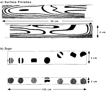
The results of this study are shown in Figures 3a and b for the Surface Finishes bar and the Zygo bar, respectively. The distance between two interference fringes corresponds to a thickness variation of [3].
While the wide sides of the Zygo bar are very flat and parallel, significant curvature is found for the narrow sides confirming the initial expectation that a large aspect ratio makes the polishing process more difficult. For both bars, thickness variations become more pronounced close to the corners. Quantitatively, we find a thickness variation of approximately 1-2 m for the Surface Finishes bar and better than 0.5 m (2-3 m, narrow sides) for the Zygo bar. Both values are acceptable for a CCT detector.
We gratefully acknowledge the support of the Department of Energy, the National Science Foundation, and the A. P. Sloan Foundation. We would also like to express our thanks to Prof. S.Iwata and Prof. F.Takasaki at KEK for their support of this work.
References
- [1] K. Honscheid, M. Selen, and M. Siverz, Particle Identification via Cherenkov Correlated Timing Nuclear Instruments and Methods, A343, 306 (1994).
- [2] M. Selen and K. Honscheid, CBX 92-116.
- [3] The factor of two comes in because the light passes through the quartz bar twice, and is the reflective index.
- [4] BaBar Detector Technical Design Report, March 1995.
- [5] Results of KEK test-beam run presented at RICH-95 by H. Kichimi.
- [6] In other words, the fraction of detected photoelectrons that arrive early enough to influence the leading edge of the phototube output pulse.
- [7] M. Kuhlen et. al. IEEE Transactions on Nuclear Science, 38, 1052 (1991).
- [8] These numbers scale with distance as .
- [9] The resolution is significantly better if particle time of flight information is included.
- [10] The term “grease” refers to the viscosity of the compound, not its chemistry.
- [11] See Dupont technical references H-54900, H-54898-1, H-58832, H-58836.