Proposal to upgrade the MIPP Experiment
Abstract
The upgraded MIPP physics results are needed for the support of NuMI projects, atmospheric cosmic ray and neutrino programs worldwide and will permit a systematic study of non-perturbative QCD interctions. The MIPP TPC is the largest contributor to the MIPP event size by far. Its readout system and electronics were designed in the 1990’s and limit it to a readout rate of 60 Hz in simple events and 20 Hz in complicated events. With the readout chips designed for the ALICE collaboration at the LHC, we propose a low cost scheme of upgrading the MIPP data acquisition speed to 3000 Hz. This will also enable us to measure the medium energy numi target to be used for the NOA/MINERA experiments. We outline the capabilities of the upgraded MIPP detector to obtain high statistics particle production data on a number of nuclei that will help towards the understanding and simulation of hadronic showers in matter. Measurements of nitrogen cross sections will permit a better understanding of cosmic ray shower systematics in the atmosphere. In addition, we explore the possibilities of providing tagged neutral beams using the MIPP spectrometer that may be crucial for validating the Particle Flow Algorithm proposed for calorimeters for the International Linear Collider detectors. Lastly, we outline the physics potential of such a detector in understanding non-perturbative QCD processes.
I Current Status of the MIPP Experiment
We give a brief status report on the MIPP experiment and its performance to date. The Main Injector Particle Production Experiment (FNAL E-907, MIPP) mipp is situated in the Meson Center beamline at Fermilab. It received approval proposal in November 2001 and has installed and operated both the experiment and a newly designed secondary beamline in the interim. It received its first beams in March 2004, had an engineering run to commission the detector in 2004 and had its physics data-taking run in the period January 2005-March 2006. The experiment is currently busy analyzing its data.
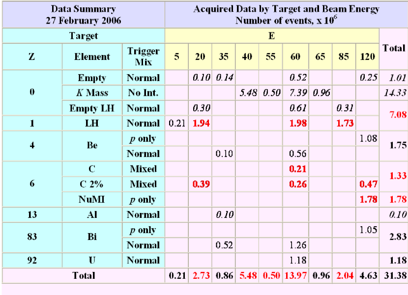
MIPP is designed primarily as an experiment to measure and study in detail the dynamics associated with non-perturbative strong interactions. It has nearly 100% acceptance for charged particles and excellent momentum resolution. Using particle identification techniques that encompass , time-of-flight tof , Multi-Cell Čerenkov e690 and a Ring Imaging Čerenkov (RICH)detector rich , MIPP is designed to identify charged particles at the 3 or better level in nearly all of its final state phase space. MIPP has acquired data of unparalleled quality and statistics for beam momenta ranging from 5 GeV/c to 90 GeV/c for 6 beam species (and) on a variety of targets as shown in Figure 1.
An important aspect of MIPP data-taking was the measurement of particle production off the NuMI minos target in order to minimize the systematics in the near/far detector ratio in the MINOS minos experiment. MIPP also made measurements with proton beams off various nuclei for the needs of proton radiography proposal .
Another physics motivation behind MIPP is to restart the study of non-perturbative QCD interactions, which constitute over 99% of the strong interaction cross section. The available data are of poor quality, and sparsely populate the beam momentum, , and atomic Weight phase space that makes comparisons between different experiments difficult. The Time Projection Chamber (TPC) tpc that is at the heart of the MIPP experiment represents the electronic equivalent of the bubble chamber with vastly superior data acquisition rates. It also digitizes the charged tracks in three dimensions, obviating the need for track matching across stereo views. Coupled with the particle identification capability of MIPP, the data from MIPP would add significantly to our knowledge base of non-perturbative QCD. This would help test inclusive scaling relations and also scaling nuclear reactions.
I.1 Experimental Setup
We designed a secondary beam carol specific to our needs. The 120 GeV/c primary protons are resonantly extracted in a slow spill from the Fermilab Main Injector and transported down the Meson Center line. They impinge on a 20 cm long copper target producing secondary beam particles. This target is imaged onto an adjustable momentum selection collimator which controls the momentum spread of the beam. This collimator is re-imaged on to our interaction target placed next to the TPC. The beam is tracked using three beam chambers and identified using two differential Čerenkovs bckov filled with gas, the composition and the pressure of which can be varied within limits depending on the beam momentum and charge.
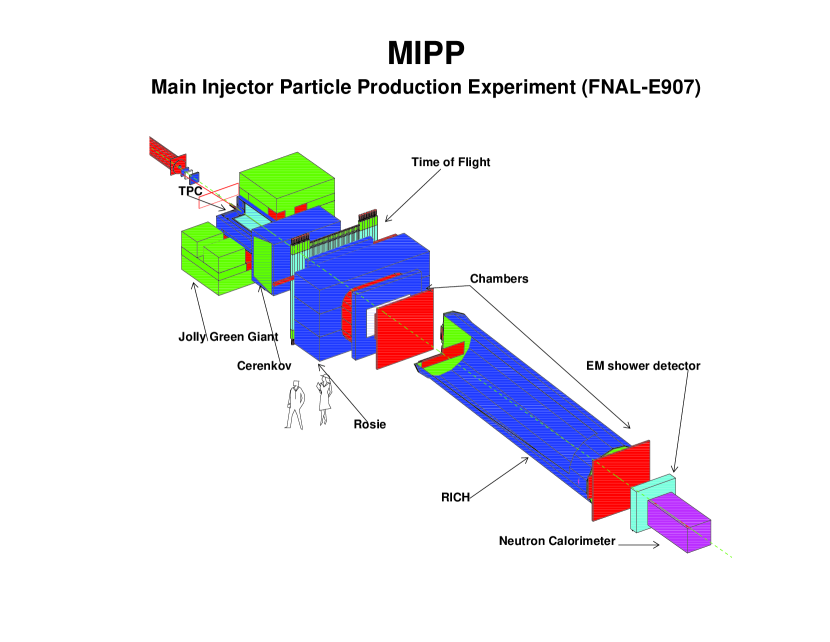
Figure 2 shows the layout of the apparatus. The TPC sits in a wide aperture magnet (the Jolly Green Giant) which has a peak field of 0.7 tesla. Downstream of the TPC are a 96 mirror multi-cell Čerenkov detector filled with gas, and a time of flight system. This is followed by a large aperture magnet (Rosie) which runs in opposite polarity (at -0.6 tesla) to the Jolly Green Giant to bend the particles back into the Ring Imaging Čerenkov counter. The RICH has as the radiator and an array of phototubes of 32 rows and 89 columns fire . Downstream of the RICH we have an electromagnetic calorimeter ecal and a hadron calorimeter hcal to measure forward-going photons and neutrons. The electromagnetic calorimeter provides a means of distinguishing forward neutrons from photons and will also serve as a device to measure the electron content of our beam at lower energies, which will be useful for measuring cross sections.
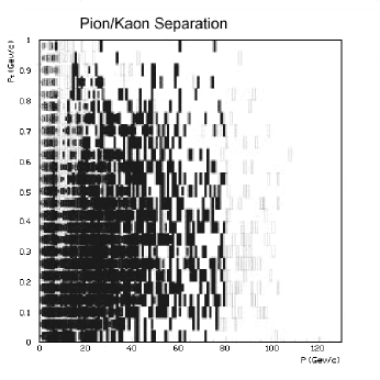
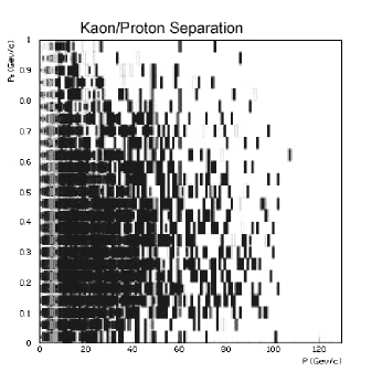
MIPP uses in the TPC to separate pions, kaons and protons for momenta less than 1 GeV/c and the time of flight array of counters to do the particle identification for momenta less than 2 GeV/c. The multi-cell Čerenkov detector e690 contributes to particle identification in the momentum range 2.5 GeV/c-14 GeV/c and the RICH rich for momenta higher than this. By combining information from all counters, we get the expected particle identification separation for and as shown in Figure 3. It can be seen that excellent separation at the or higher level exists for both and over almost all of phase space. Tracking of the beam particles and secondary beam particles is accomplished by a set of drift chambers chambers1 and proportional chambers chambers2 each of which have 4 stereo layers.
I.2 Some results from Acquired data
Figure 4 shows the pictures of reconstructed tracks in the TPC obtained during the data-taking run. The tracks are digitized and fitted as helices in three dimensions. Extrapolating three dimensional tracks to the other chambers makes the pattern recognition particularly easy.
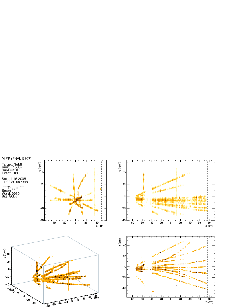
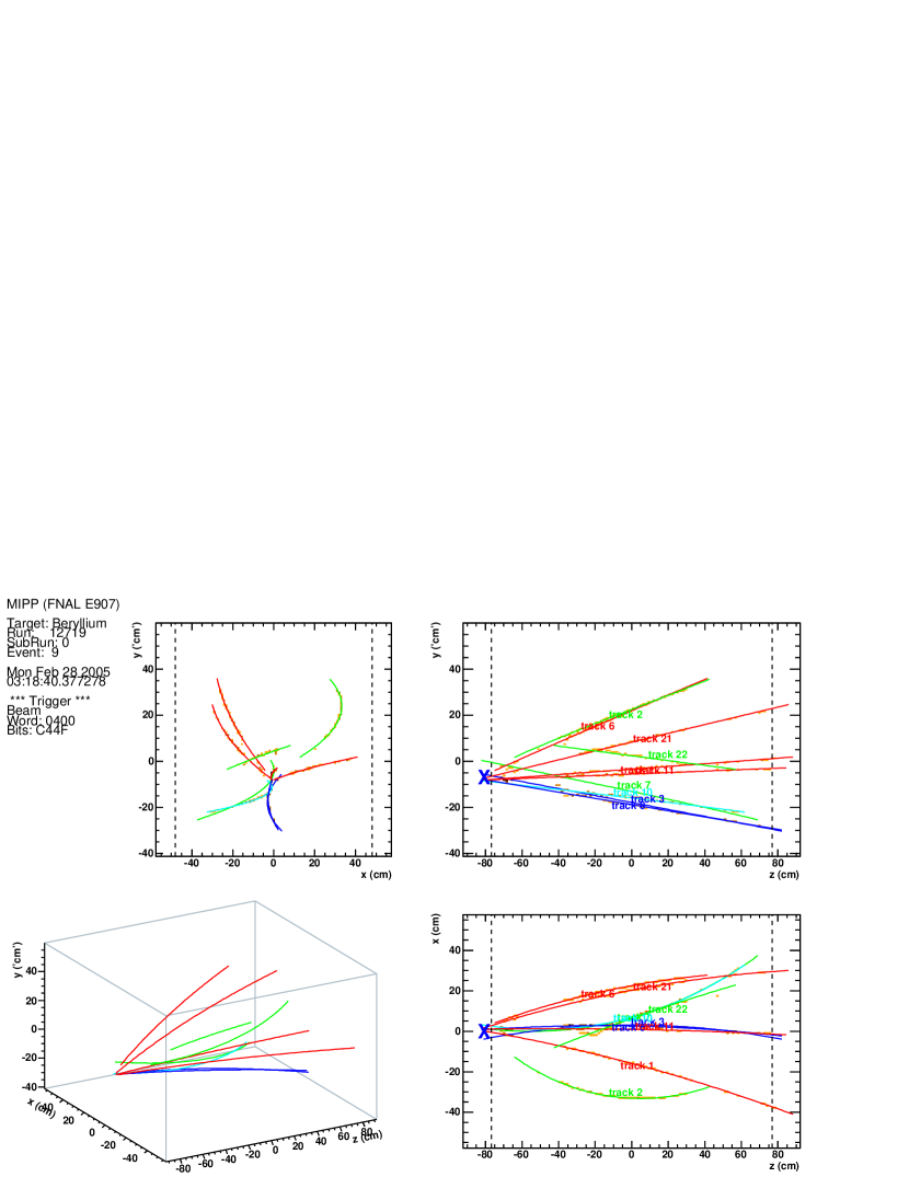
Figure 5 shows the distribution of of tracks measured in the TPC as a function of the track momentum in a preliminary analysis of p-Carbon data. The TPC is capable of separating pions, protons and kaons in the momentum range below 1 GeV/c.
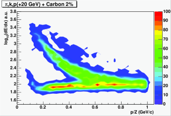
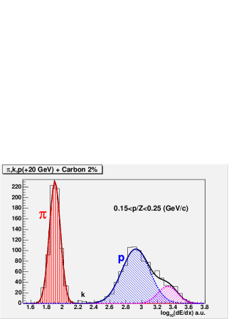
Figure 6 shows events with rings in the RICH counter. Some are due to single beam tracks and others are due to tracks from interactions.
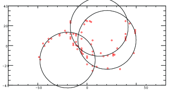


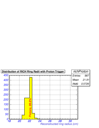
Figure 7 shows the histogram of ring radii for a +40 GeV secondary beam. There is clean separation between pions, kaons and protons and their relative abundances malensek match expectations. Applying the particle identification trigger from the beam Čerenkovs enables us to separate the three particle species cleanly. The kaons which form 4% of the beam are cleanly picked out by the beam Čerenkov with very simple selection criteria. These can be made much more stringent with offline cuts to produce a very clean kaon beam.
The ring radius of the particle contains information on the mass of the particle. The pion and proton masses are very well known. The charged kaon mass, however, currently has measurement uncertainties of the order of 60 keV. Improving the precision of both charged kaon masses will pay dividends in CP violation experiments involving charged kaons where the matrix elements depend on the kaon mass raised to large powers. Towards the end of our physics run, when the Jolly Green Giant magnet coils failed, we switched off the TPC and acquired data at the rate of 300 Hz to investigate how well we can measure the charged kaon mass. These events, whose statistics are indicated in Figure 1, are currently being analyzed to evaluate the systematics involved in such a measurement.


I.2.1 NuMI target measurements
MIPP took 1.75 million events using 120 GeV/c primary beam protons impinging on the NuMI (spare) target. These events will play a crucial role in the prediction of neutrino fluxes in the NuMI beamline and will enable the MINOS experiment to control the systematics in the near/far detector ratios as well as helping them understand the near detector performance. Figure 8 shows a radiograph of the MIPP measurements of the MINOS target. The graphite slabs and cooling tubes can be seen. These events were obtained during the commissioning phase of this target measurement where the beam was not yet fully focussed and aligned on the target. The 1.75 Million events on the NuMI target were obtained after the beam was aligned and centered on the target.
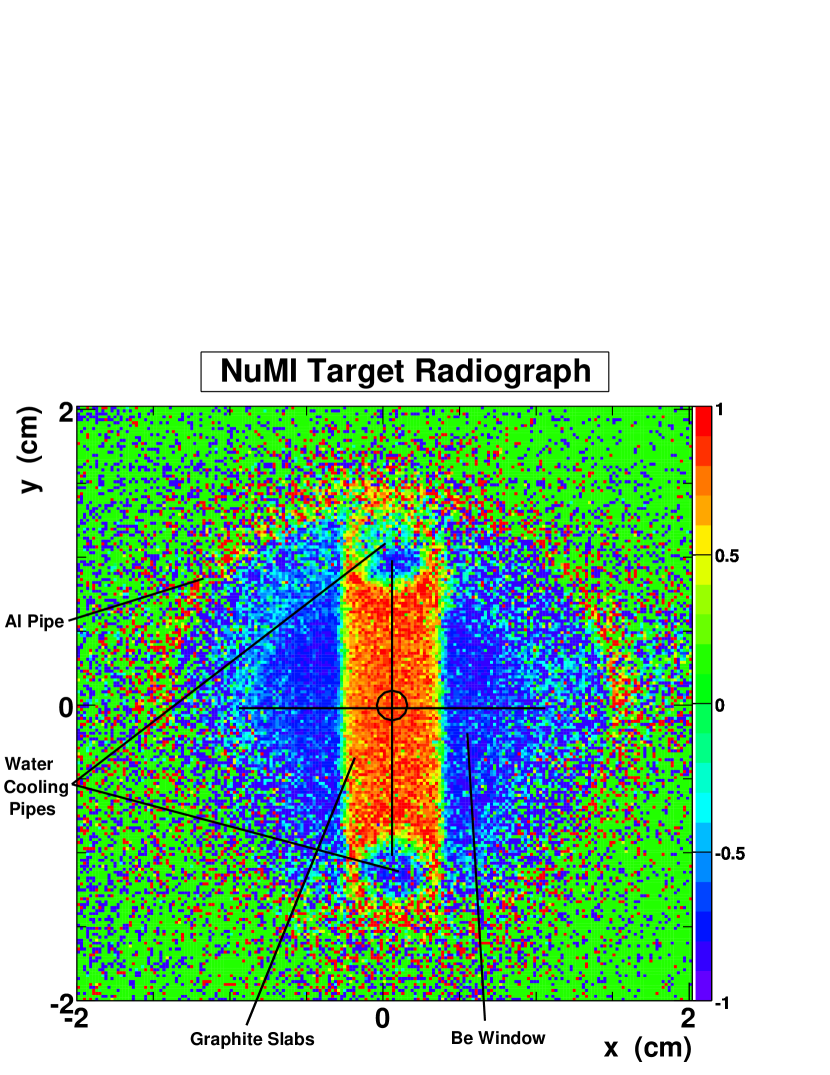
Figure 9 shows the rich ring radii vs momentum of positive tracks originating from the NuMI target. Superimposed are the curves for known particles. This shows the excellent particle identification of the MIPP detector for forward going particles.

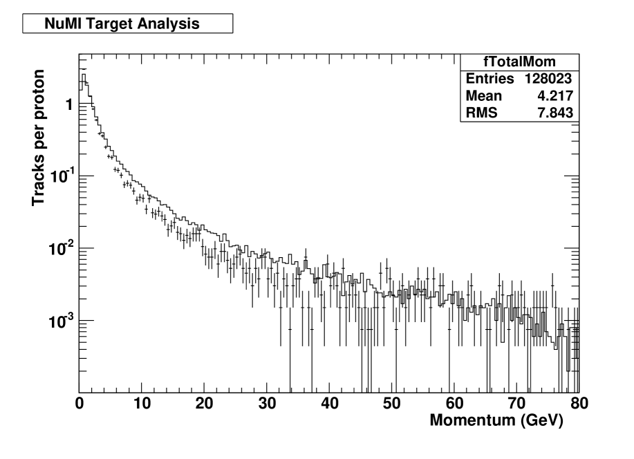
Figure 10 shows the results of a preliminary analysis of NuMI target data in both energy spectrum of the tracks and track multiplicity and compares it to the FLUKA Monte Carlo.

I.2.2 Target fragmentation multiplicities as a function of Atomic Number
We have analyzed the multiplicities in the TPC as a function of Atomic number A of the target. Here we show (Figure 11) a preliminary analysis of the multiplicity of both positive and negative tracks in the momentum range 0.1 GeV/c-1.0 GeV/c for the nuclear targets , Be, C, and Bi for 3 positive beam species and p at 58 GeV/c incident momentum. The data show a rise in target fragmentation multiplicity as a function of A. The positive multiplicities are higher, reflecting the charge of the target.

II The proposal in a nutshell
II.1 Beam Delivery rate assumed
In what follows, we will assume that the Main Injector delivers one 4 second slow spill every two minutes to MIPP in the upgraded mode, with a machine downtime of 42%, and that the MIPP DAQ has been upgraded to run at 3 kHz. These are conservative estimates of machine delivery rate and downtime. At this rate, we are capable of acquiring 5 Million events per day.
II.2 Replacing the Jolly Green Giant Coils
One month before the end of our run in March 2006, the Jolly Green Giant magnet failed. Two of its 4 coils became inoperative due to shorts. The Jolly Green Giant coils were fabricated in the 1960’s and have seen a lot of power cycles. Even if we fix the broken coils, there is no guarantee as to how long the remaining coils will last. We have decided to replace all four coils with two aluminum coils with the same field strength as before. The aluminum conductor is cheaper than copper. In the process, we have made the coils longer along the beam direction by 9 inches so as to provide a more uniform field for the electron drift in the TPC.
II.3 TPC DAQ upgrade
The MIPP sub-detector with the largest data output is our TPC. It is also the slowest in outputing this data, since its data acquisition electronics were designed and built Rai90 in the early 1990’s. The TPC runs at 60 Hz for very simple events (single beam tracks). For complicated events this rate currently falls to 20 Hz. With modern electronics, it is possible to increase the DAQ rate to 3000 Hz, resulting in an over-all increase of 150 in our data acquisition capability. We propose to use the ALTRO/PASA chips designed and tested for the ALICE collaboration at the LHC Musa03 . This technology is also being used for the STAR , BONUS and TOTEM experiments. A production run for these experiments is being negotiated now. If MIPP were to get in on this order, the total cost to MIPP to procure these chips (1100 of them) would be $80,000.
We propose to acquire these chips and design and fabricate new front end electronics cards for the TPC. With one 4-second slow spill every two minutes and allowing for a machine down-time of 42%, we can accumulate 5 Million events per day.
II.4 Upgrade of the Rest of the DAQ
We propose to improve the way MIPP is triggered, the DAQ electronics of the drift and wire chambers, the time of flight and threshold Čerenkov counters and the calorimeters. The only system that remains unaltered is the RICH for which we built front end electronics for the first run. We briefly outline the changes to the detector DAQ here.
II.4.1 Triggering
We will trigger MIPP using silicon pixel systems that were developed for the BTeV experiment. We will have one pixel plane before the target and two after the target. We will have a trigger scheme that will project on the downstream pixels planes the expected un-interacted beam position (the bulls-eye) and trigger the experiment if pixels outside this bull’s eye are hit. This scheme will enable us to trigger on low multiplicity events (including elastics) in an unbiased fashion. This would improve the existing MIPP trigger system that utilized a combination of a scintillator counter in conjunction with the first drift chamber multiplicity to provide the interaction trigger. While this system performed satisfactorily in our first run, it suffered from Landau fluctuations in the scintillator and periodic over-efficiency in the wire chamber. The digital nature of the pixel signal eliminates Landau tails completely.
II.4.2 Chamber electronics
We propose to replace the aging drift chamber electronics (remnants of the E690 system) with a more modern electronics system designed and built in-house at Fermilab. We will use the same electronics for the Proportional chambers to replace RMH electronics.
The current drift chamber electronics with a large power consumption stresses the air conditioning in MC7 to the limit. The new electronics will cause significantly less heating.
The Chamber electronics will utilize the same VME readout cards as the new TPC electronics. This reduces initial design costs and also simplifies the detector readout.
II.4.3 Time of flight system and threshold Čerenkov detector
We propose to replace the ToF and Čerenkov detector readout electronics with electronics designed and built in-house. This design will also utilize the same VME readout cards as used for the TPC readout.
II.4.4 Calorimeter readout
The calorimeter readout electronics is currently too slow to obtain the desired 3000Hz readout rate. We propose to replace this electronics with a FERA adc system read out through new commercial CAMAC branch controllers.
II.5 Upgrading the beamline to run at lower momenta
The MIPP secondary beamline performed very well during our physics run which concluded in March 2006. Figure 12 shows a cut view of the beamline elements.

During our run, we managed to operate the beamline as low as 5 GeV/c and as high as 120 GeV/c for the NuMI target run (The secondary beam production target was removed and a pinhole collimator inserted to reduce the Main Injector intensity). The beamline has been operated as low as 1 GeV/c to measure the flux available, which was adequate. What is lacking is the ability of the magnet power supplies to regulate the very small currents. We propose to add low-current magnet power supplies that are capable of this. We will switch to these power supplies during our low momentum running. The residual field of the iron yokes becomes significant at these low currents. Hall probes will be added to the beamline magnets to monitor their field so that hysteresis effects can be compensated for.
II.6 Other tasks
We propose several small improvements to the MIPP experiment to increase reliability and maintainability of the experiment. These include several changes to the gas systems, the cryogenic target, and slow monitoring, as well as maintenance on Drift chambers and photomultiplier tubes for the RICH and CKOV detectors.
In the present experiment, we operated a single scinitillator veto counter (which had a hole in it to let the beam through) to guard against beam spray. We plan to add to this counter and build a veto wall for the upgrade. In addition, a recoil detector (the Plastic Ball) will be added to detect low energy particles (both charged and neutral) that are produced at wide angles ( to the beam) and miss the TPC.
III Summary of the proposed physics for the Upgraded MIPP run
III.1 Particle Production on neutrino targets in the NuMI beam
We outline here the need to measure the particle production on the NuMI targets. In a disappearance experiment such as MINOS, the evidence of neutrino oscillations is obtained from the difference in shapes of the energy spectrum of the neutrino charged current events in the far detector and the near detector. Because of the finite size of the NuMI target and decay region, the angles of the decaying pions that produce neutrinos reaching the near detector have a different distribution than those reaching the far detector. Put another way, the neutrinos that interact in the near detector come from the decay of a different kinematic mix of pions than those that interact in the far detector. It is thus important to measure the dynamics of pion production off the NuMI target.
Figure 13 shows the distributions in longitudinal and transverse momentum of pions weighted by their contribution to the neutrino event rate in the far and near MINOS detectors. These weightings are different in detail. Superimposed on this plot are existing data on hadron production obtained from mainly single arm spectrometer measurements hadrprod , which explains their discreteness in space.

Figure 14 shows the predictions of the absolute neutrino rates in the MINOS near detector using four existing hadron production models hadmod . The model predictions differ from the average by as much as 20% as a function of neutrino energy.

Figure 15 shows the predictions of the ratio of the far to the near neutrino flux using the same four models. Again, there is considerable uncertainty in the predictions, which increases in the high energy tail of the spectrum. The evidence for oscillations is obtained by normalizing the far detector spectrum to the near detector spectrum ( more events in the near detector). The shapes of the two spectra have to agree in the high energy tail (no oscillations), before one can take seriously the expected deficit due to oscillations (in the low energy part of the spectrum).

Figure 16 shows the variation of the percentage error in the far/near detector ratio as a function of the number of events obtained in MIPP off the NuMI target, for neutrino energies (3-4 GeV, low energy part, oscillation deficit) and for neutrino energies (20-22 GeV, high energy tail). It can be seen that one needs events in MIPP on the NuMI target for this percentage error to drop below 3% in the high energy tail.

MIPP has so far obtained 1.75 million events on the NuMI target currently installed in the MINOS experiment using 120 GeV/c protons from the Main Injector.
III.1.1 MINOS analysis
MINOS has analyzed its near and far detector data and published confirmatory evidence of neutrino oscillations minobs and the best estimates for the oscillation parameters and . Details of their near and far detector analysis have been reported at conferences sacha . We reproduce some relevant plots from the analysis done so far to highlight the uncertainties associated with hadron production Monte Carlos and the need to measure the particle production first hand. Figure 17 shows the prediction of the near detector spectrum using a number of Monte Carlos for the low, medium and high energy NuMI beam settings. The spread in the Monte Carlos is indicated by the shaded error bar. The predictions of the near detector spectra utilize the Monte Carlo fluxes, the neutrino cross section and the detector resolution and trigger efficiencies and acceptances. The Monte Carlos systematically underestimate the low energy spectrum in the 6-18 GeV range. They also overestimate the the medium energy spectrum in the same energy range. This leads to the conclusion that the predictions of the hadron spectra are to blame and not the neutrino cross section for the mismatches. MINOS then proceeds to weight the Monte Carlo spectrum to match the near detector events and then uses the re-weighted spectrum to predict the far detector response as a function of the oscillation parameters.

Figure 18 shows the predictions of the near/far ratio for three Monte Carlos, FLUKA01, FLUKA05 and MARS. The predictions between FLUKA01 and FLUKA05 differ, even though there has been no new particle production data introduced into the code. The change is purely due to model development.

MINOS has done a more thorough analysis of the near detector predictions as a function of their target position and also the horn current. Figure 19 shows the predictions for the low energy target setting with the target at the “10 cm” position LE10 and the horn current at 185 kA. At the point of maximum disagreement between the Monte Carlo predictions and data, the weight factor is 1.4.
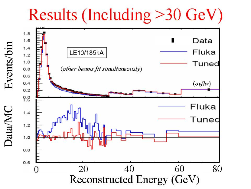
These re-weighting uncertainties in the Monte Carlo are ameliorated in MINOS’s case by the excellent performance of their near detector. It would however be still desirable to remove all uncertainties by obtaining the needed events, which the MIPP upgrade can do in 2 calendar days of running.
All of MINOS’s largest systematic uncertainties are related in some fashion to neutrino cross section uncertainties and event shape modeling. These will also improve with improved neutrino beam predictions.
III.1.2 Measuring the NOA/MINERA target
MINERA has requested sufficient running in the NuMI LE beam, as used by MINOS, to measure the low-energy cross sections and nuclear effects so important for MINOS systematics. Neutrino cross sections need a first principles measurement of the particle spectrum. The MIPP sample of events off the LE target can be used directly by MINERA to estimate their neutrino spectrum without recourse to any particle production Monte Carlos.
The NOA medium energy target has still to be designed. When it becomes available, MIPP can measure the particle spectrum from this target, again obtaining a sample of events. This will help the MINERA experiment obtain cross sections using the medium energy target and the NOA experiment with its backgrounds and systematics in its search for electron neutrino appearance.
III.1.3 Benchmark test of Monte Carlos at the Hadronic Shower Simulation Workshop
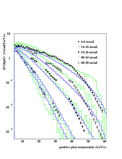
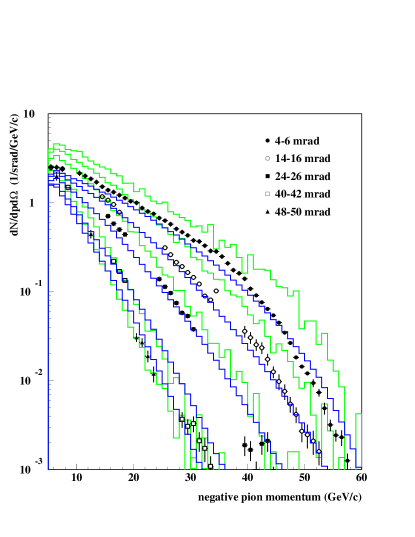
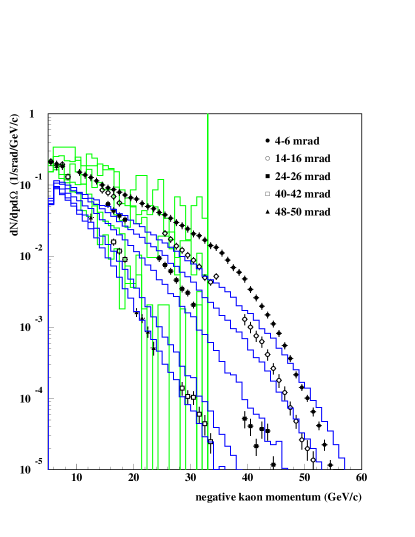
At the recently concluded Hadronic Shower Simulation Workshop at Fermilab hssw06 , a series of benchmark tests were performed to test various Monte Carlo codes. We show results from one such benchmark that is relevant to the prediction of neutrino fluxes. Data on particle production by 67 GeV/c protons on an aluminum target (60 cm long and 3 cm in radius) obtained in Protvino were compared to the predictions of the MARS and PHITS monte carlos. Figure 20 shows the comparison of the spectra with the Monte Carlo predictions and Figure 21 shows the comparison of the spectra with the Monte Carlo predictions as a function of production angle and energy. It is clear that the Monte Carlos disagree with each other and data underscoring the need for a first principles measurement of particle production of neutrino targets.

III.2 Particle production on Nitrogen and the question of Cosmic Ray Showers in the Atmosphere
We propose to measure particle production on a cryogenic nitrogen target using positive and negative beams, which is needed by experiments measuring cosmic ray air showers (Pierre Auger, HiRes etc) and also atmospheric neutrinos (Amanda, Ice Cube, HyperK etc). The problem is illustrated in a recent paper meurer that simulates extensive air showers to illustrate the problem. They simulate the air showers produced by protons of GeV energy in the atmosphere. The shower goes through several generations of interactions and produce pions and kaons that decay to produce muons and neutrinos. The muons and neutrinos are observed in the detectors and are termed the daughter particles. The mesons that produced the muons and neutrinos are termed the mother particles and the particles that interacted in the atmosphere to produce the mother particles are termed the grandmother particles in their jargon.
Figure 22 shows the energy spectrum of the grandmother particles ( and in an air shower that are produced by a primary proton of GeV. The spectrum for the pions peaks at 100 GeV and the kaons and protons at somewhat higher energies. These particles interact with the nitrogen (and oxygen) in the atmosphere to produce the atmospheric neutrinos and muons. In other words, the beam energies available at MIPP are relevant to the simulation of the cosmic ray air showers. The muon flux measurement is a critical component of estimating the energy scale of the cosmic ray shower. MIPP measurements thus will help reduce the systematics in the cosmic ray energy scale measurements. As the primary cosmic ray energy increases, the peaks in this plot do not shift to higher energies. Understanding the shower systematics at the peak of this spectrum (i.e MIPP energies) will help the energy systematics of cosmic rays of all energies.
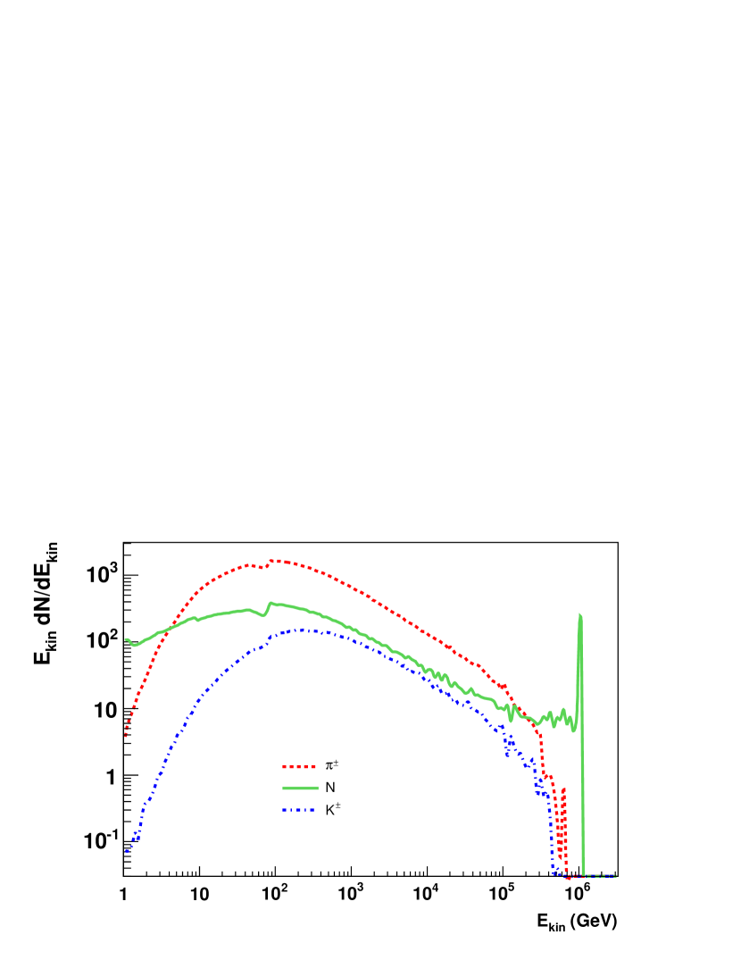
Figure 23 shows the distribution of grandmother particles at different lateral distances from the shower center for all particle types. For the lower energy interactions, the simulation code Gheisha is used to simulate the interactions of the particles with the atmosphere. For higher energy interactions, the simulation code QGSJET 01 is used. The sharp break in the spectra at 100 GeV is where the two codes meet and disagree at places by a factor of two. This illustrates the problem. These codes at present are “tuned” on single arm spectrometer data and disagree with each other.
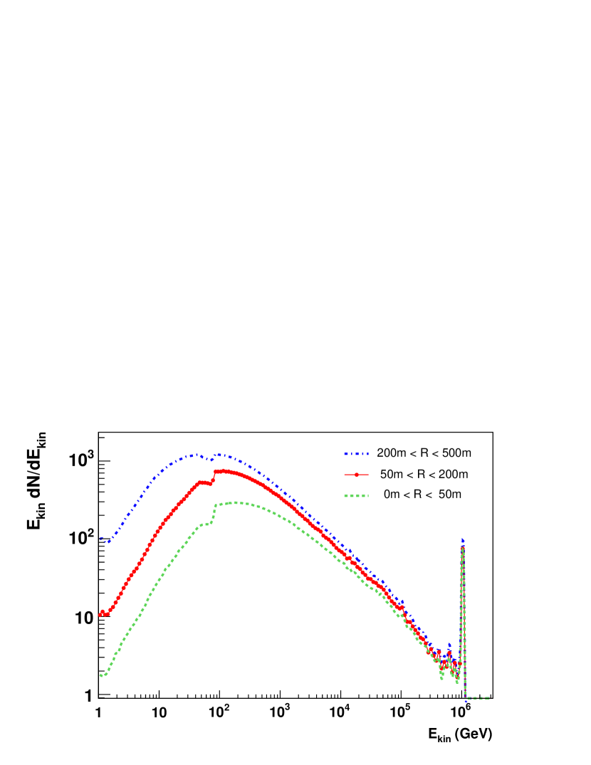
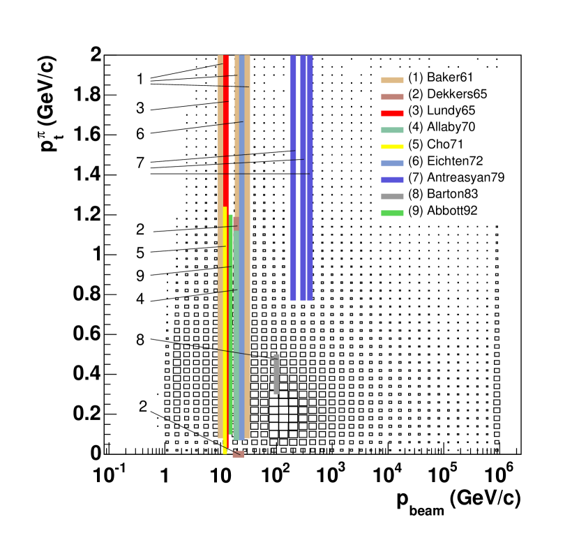
Figure 24 shows the momentum of grandmother particles versus the momentum of the mother pions in the air shower and plots the existing data relevant to simulating the process. Most of the data are over 25 years old and were obtained using Beryllium targets and single arm spectrometers resulting in a discrete angular coverage. MIPP will measure the outgoing pion and kaon spectrum for proton and pion beams in its full secondary beam momentum range. These cross sections are the most important in simulating cosmic ray showers in the atmosphere. In addition, it will also have kaon and antiproton interactions on nitrogen of which virtually nothing is known. Being an open geometry experiment, the MIPP angular coverage will be continuous, not discrete.
The need for MIPP data is recognized by the cosmic ray community, some of whom have joined this proposal.
III.2.1 MIPP Measurement of ratios
Because of its excellent particle identification capabilities, MIPP upgrade will measure the ratio of charged kaons to pions as a function of of the final state particle. This measurement is of importance to both the NuMI target measurements and the atmospheric neutrino measurements, since the charged K’s produce which are a background to the oscillation search .
III.3 Hadronic production on Nuclei and the Hadronic Shower Simulation Problem
At the recently concluded workshop on Hadronic Shower Simulations hssw06 , experts in shower simulation codes from five major Monte Carlos (GEANT4, FLUKA, MARS, MCNPX, and PHITS) (and several less well-known ones) met and reviewed their code status and what needs to be done further to improve codes. It was acknowledged that more particle production data would help improve algorithms a great deal and there were calls for a rapid publication of existing MIPP data and enthusiastic support for the MIPP upgrade.
The problem of hadronic shower simulations stems from our lack of understanding of the strong interaction. Though a theory of strong interaction exists (QCD), it cannot be used to calculate fundamental non-perturbative processes such as elastic cross sections, diffractive cross sections or any of the particle production cross sections that comprise 99% of the total cross section. This is in stark contrast to the simulation of electromagnetic showers where Monte Carlos such as EGS regularly make predictions that can be verified by observation.
The minimum bias cross section is modeled in most of the above mentioned Monte Carlos using the supercritical pomeron (which in itself violates unitarity). By application of the optical theorem, cut pomerons produce the total cross section. The cut pomeron is approximated by a quark gluon string which is then hadronized. This is the basis of the particle production models such as DPMJET and QGSJET which are used in Monte Carlos such as GEANT4 and MARS. The soft part of the scattering and the hard part of the scattering cross section are joined very carefully, but arbitrarily.
Nuclear break-up is handled using a plethora of models that go by the name of binary cascade, Bertini cascade, CHIPS (Chiral Invariant Phase Space), CEM03 and GEM2, each of which have different assumptions on the nuclear break-up mechanism.
Each of these Monte Carlos are “validated” using existing data. Inclusive particle spectra from single-arm spectrometer experiments that are over 30 years old are used. These data are discrete in the transverse momentum variable and have systematics that are significantly greater than open geometry experiments such as HARP, NA49 and MIPP. These models are made to agree with inclusive particle spectra. Predictions of correlations between particles are not tested against, since such data do not exist in readily testable form. However, calorimeter designers are currently asking questions such as how wide a hadronic shower is in a calorimeter, which depends on particle correlations.
Another important part of calorimetric simulation of hadronic showers is the nuclear break-up and the number of spallation neutrons and protons emitted, as emphasized by Wigmans wigmans . The linearity of the calorimeter and the resolution of the calorimeter depend critically on compensating for the “invisible energy” in a hadronic shower carried away by neutrons and nuclear binding energy. It is important to model these processes correctly. It is not at all clear as to how well the above mentioned nuclear break-up models simulate these processes.
To illustrate this further, table 1 shows wigmans how the energy is deposited by a 1.3 GeV pion in lead. The energy is deposited as ionization , as binding energy required to split the nucleus, as cascade nucleons and evaporation nucleons (isotropic emission). Please note that on average only 478 MeV of a 1.3 GeV pion ends up as ionization energy and the rest is carried away as neutrons and also absorbed as binding energy. The whole question of compensating calorimetry hinges on using the neutrons to produce knock-on protons to compensate for this invisible energy, since energy from the neutrons can be made to be visible by introducing hydrogenous materials in the calorimeter in appropriate proportions, resulting in knock-on protons caused by neutron elastic scattering that deposit visible energy.
| Binding | Evaporation n | Cascade n | Ionization | Target | |
|---|---|---|---|---|---|
| Energy | (# neutrons) | (# neutrons) | (#cascade p) | recoil | |
| Before first reaction | (250)() | ||||
| First reaction | 126 | 27(9) | 519 (4.2) | 350(2.8) | 28 |
| Generation 2 | 187 | 63(21) | 161(1.7) | 105(1.1) | 3 |
| Generation 3 | 77 | 24(8) | 36(1.1) | 23 (0.7) | 1 |
| Generation 4 | 24 | 12(3) | |||
| Total | 414 | 126(41) | 478(4.6) | 32 |
The upgraded MIPP spectrometer can measure nuclear multi-particle hadronic production using 6 beam species (, ) and in the momentum range 1 GeV/c-120 GeV/c. The TPC can measure the protons from nuclear breakup that travel forward in the laboratory and the plastic ball detector will detect the evaporation neutrons and protons emitted backwards in the laboratory. We can measure 30 nuclei in 30 days of running and obtain data of unprecedented quality and statistics on nuclei commonly encountered in particle physics detectors.
We propose as a first priority (“A-List”)
to measure particle production on the nuclei
H2,D2,Li,Be,B,C,N2,O2,Mg,Al,Si,P,S,Ar,K,Ca,
Hg,Fe,Ni,Cu,Zn,Nb,Ag,Sn,W,Pt,Au,Pb,Bi,U
and as a second priority (“B-list”)
the nuclei
Na,Ti,V, Cr,Mn,Mo,I, Cd, Cs, Ba
These data can be used to validate the Monte Carlos to unprecedented accuracy or may even by usable directly as a library of events in a fast Monte Carlo rajalib .
It is worth pointing out that the MIPP upgrade proposal represents a unique opportunity to obtain such a dataset. Comparable experiments such as HARP do not possess kaon or antiproton beams and do not have the range in beam momentum (3-15 GeV/c primary momentum). HARP took data The proposed NA49 upgrade does not posses the data-taking rate (20 Hz compared to 3000 Hz in MIPP) nor the particle id capabilities of MIPP (no forward RICH detector), though, being an SPS experiment, it has higher beam momenta (positive beams only, maximum beam momentum 158 GeV/c). Nevertheless, these two detectors will provide valuable data in the near future on particle production.
Lastly, there is a misunderstanding among some that putting test hadronic calorimeter modules in the test beam and comparing the predictions of simulation programs such as GEANT4 and FLUKA to the observed data can help tune the hadronic models in the simulation programs. This myth was debunked at the Hadronic Shower Simulation Workshop, when the Geant4 group collectively answered a question by stating that “We only change our models based on microscopic data” g4gr . Upon being asked what “microscopic” meant, they answered, thin target nuclear data. It is difficult to unfold the various nuclear and readout effects in calorimeter data to change the models. In other words, the only way to improve the simulation models is by experiments such as MIPP, HARP and NA49 that measure hadro-production using thin targets.
III.4 Tagged Neutral beams and ILC Detector R&D
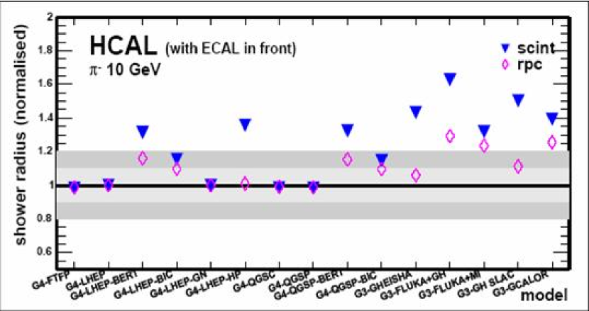
Three out of the four ILC detector concepts (SiD, LDC, GLD) are optimized around the particle flow algorithm (PFA), which proposes to measure the energy of jets in an event by using both the magnetic field and the calorimeter. The charged particles are measured using the excellent momentum resolution of the tracker and the neutral particles are measured using the calorimeter. The required fractional energy resolution of a jet is , E in GeV. This hard-to-achieve performance is driven by the ILC design requirement to be able to separate the processes and . In order to measure the neutral particle energy using the calorimeter, one needs to separate the charged particle hits and the neutral particle hits in the calorimeter. This dictates a highly segmented calorimeter. In order to test the design, one needs to simulate the widths of the showers of both the charged and neutral particles in the calorimeter. Figure 25 shows the simulation of the width a 10 GeV particle entering two ILC calorimeters, one using RPC readout and the other using scintillator readout cwid-guy for a variety of hadronic shower simulators available in Geant4 and Geant3. The widths are normalized to the narrowest width obtained. There is a variation in the widths of in the simulations. This calls for a data-based approach both for charged and neutral hadronic responses. The charged response can be obtained in a regular test beam such as would be available at Fermilab in the M-test area. The upgraded MIPP spectrometer offers a unique opportunity to measure the neutral particle response to three neutral species, the neutron, the and the anti-neutron.
The basic idea is to use the diffractive reactions
| (1) | |||
| (2) | |||
| (3) | |||
| (4) |
where the beam of protons, or fragments diffractively to produce the neutral beam. The charged particles in the reaction are measured in the MIPP spectrometer. The beam momentum is known to 2%. So the momentum of the tagged neutral particle can be inferred by constrained fitting (3-C fit) to better than , event by event. The tagged neutral particle goes along the beam direction and ends up in a test calorimeter placed in lieu of the present MIPP calorimeter.
This technique demands that the target is a proton and will only work on a liquid hydrogen cryogenic target (that MIPP possesses). The plastic ball recoil detector will act as an additional veto against neutral target fragments such as slow .
The momentum spectrum of the neutral beam is controllable by changing the beam momentum. The method is outlined in detail in MIPP note 130 raja130 . The diffractive processes are simulated using the program DPMJET and the event rates estimated for a calorimeter placed in the MIPP calorimeter position. With the MIPP upgrade, it should be typically possible to obtain 50,000 tagged neutrons, 9,000 tagged , and 11,000 tagged per day in the calorimeter with the beam momentum set to 20 GeV/c. Table 2 shows the expected number of events /day as a function of beam momentum and beam species.
| Beam Momentum | Proton beam | beam | beam | beam |
| GeV/c | n/day | /day | /day | /day |
| 10 | 20532 | 4400 | 4425 | 6650 |
| 20 | 52581 | 9000 | 9400 | 11450 |
| 30 | 66511 | 12375 | 14175 | 13500 |
| 60 | 47069 | 15750 | 14125 | 13550 |
| 90 | 37600 | - | - |
Figure 26 shows the momentum spectrum of tagged neutrons accepted in the calorimeter as a function of the beam momentum. Other similar plots are available in MIPP note 130 raja130 .

IV Non-perturbative QCD physics
The upgraded MIPP detector will provide high statistcs data using hydrogen and nuclear targets that will permit the investigation of non-preturbative QCD with unprecedented statistics. Here we list a number of such topics that can be addressed by the upgraded spectrometer. Indeed, a large fraction of the liquid hydrogen running can be done symbiotically with the tagged neutral beam running.
IV.1 Further testing of a Scaling Law of Hadronic Fragmentation
The scaling law in question scale states that the ratio of a semi-inclusive cross section to an inclusive cross section involving the same particles is a function only of the missing mass squared () of the system and not of the other two Mandelstam variables and , the center of mass energy squared and the momentum transfer squared, respectively. Stated mathematically, the ratio
| (5) |
i.e., a ratio of two functions of three variables is only a function of one of them. The physics behind the scaling law may be understood by considering inclusive cross sections as the analytic continuations of crossed three body interactions, which factorize into a production term that results in the formation of a short-lived fireball of mass , which subsequently decays into the subset in question. The formation is governed by and . The decay term is only a function of . It should be noted that the physics in question falls outside the scope of perturbative QCD and as such the scaling law is not currently derivable from QCD considerations.
In the MIPP data already taken, we managed to acquire 5.65 million events on liquid hydrogen at beam momenta 20 GeV/c, 60 GeV/c and 85 GeV/c. These are currently being analyzed and will form the basis of testing the proposed scaling law as a function of both and .
With the upgrade, we can extend the test of the scaling relations with two particle inclusive final states, which will require higher statistics due to the larger number of variables to test against.
IV.2 Antiproton Interactions in MIPP
The FAIR project has been approved by the German government and will provide a facility for research into anti-proton and ion interactions at GSI Darmstadt. The start of construction is planned for 2007 with the first experiments being set for 2012 and the completion of the project is scheduled for 2014. The cost of the project is 1 billion euros. PANDA panda is one of the flagship experiments at FAIR and stands for Proton ANtiproton DArmstadt).
The GSI-KVI group are interested in measuring cross sections of antiprotons on hydrogen and other nuclear targets in MIPP to help them design the PANDA detector. MIPP has antiproton beams with momenta as high as 60 GeV/c and as low as 3 GeV/c. The excellent particle identification capabilities of MIPP will enable a systematic study of anti-proton interactions in particular the annihilation cross section.
The PANDA experiment proposes to measure interactions in the charmonium range and higher. They are also interested in the magnitude of open charm production in interactions of which little is known in this energy range. The presence of pixel planes in MIPP might facilitate a measurement of these rare processes.
IV.3 High Multiplicity Events in MIPP and the question of bosonic condensation
We propose to investigate the production of high multiplicity events in interactions where excesses may exist due to the occurence of Bose-Einstein interference sissakian in multi-pion production. This study can be done on the large sample of interactions we will collect using the liquid hydrogen target.
The goal is to investigate collective behavior of particles in multiple hadron production in pp and pA interactions at the beam energy Elab=30 - 120 GeV. We will study the domain of very high multiplicity (VHM) for , where . At large multiplicities, near the threshold of reaction, all particles will have small relative momentum with respective to each other. In a thermalized cold and dense hadronic gas a number of collective effects listed below may show up as a consequence of multiboson interference.
-
•
A large increase of partial cross section (n) of n identical particles production is expected, compared to the commonly accepted extrapolation.
-
•
Formation of jets consisting of identical particles may occur (pionic laser).
-
•
Large fluctuation of charged n(, ) and neutral n() components, onset of Centauros or chiral condensate effects may occur.
-
•
Increase of the rate of the direct photons as the result of the bremsstrahlung in partonic cascade and annihilation + in dense and cold pionic gas or condensate is expected. The creation of a multipion bound state is possible which in the course of its formation emits soft photons.
-
•
In the domain of high multiplicity, the major part of the center of mass energy is materialized leading to high density of hadronic system. At this condition a phase transition to cold Quark Gluon Plasma may occur.
-
•
The momenta of produced particles in the center of mass system in the VHM domain are small. Then the multi-particle Bose-Einstein correlation may be readily seen. The latter can lead to the “hadron laser” effect, and the enhancement of soft gamma-quanta production.
-
•
We expect a uniform energy distribution over produced particles due to thermalization in this regime.
The process of energy dissipation in hadron interactions poses a complicated problem for theory. For instance, the event generator Pythia gives the cross section (z), at , two order of magnitude lower than the experimental value, see Figure 27. Hence further experimental and theoretical investigations are crucial to solve this problem. It may be closely connected to the vacuum structure of QCD and the confinement phenomenon. MIPP can investigate the properties of multiboson systems in the domain of low temperature and high density where pions may be in a state of boson condensation. The estimates shows that the temperature of the hadronic system becomes lower than 25 MeV at a multiplicity of . At such a temperature, the pionic gas may be in a condensate state. MIPP offers a unique opportunity to investigate the above-mentioned problems. Using the partial cross section extrapolation (Figure 27) one can estimate the counting rate in the VHM domain. As an example, for z=4, the partial cross section is 0.2 . In a 10 day run on the hydrogen target, we will collect 50 Million events, in which there will be 300 events with . According to theoretical estimates, the multiparticle enhancement effects could become prevalent in the multiplicity domain z 4, resulting in a greatly increased rate in this region.

IV.4 Baryon Spectroscopy with the upgraded MIPP
Partial-wave analyses of scattering data have yielded some of the most reliable information about nonstrange baryon resonances. These analyses provide information about resonance masses and total decay widths (or their pole positions) and branching fractions. In order to determine resonance couplings to other channels, it is necessary to study inelastic scattering reactions, such as , , and , to give only a few of many possible examples. Important information is also provided by meson photoproduction experiments, such as , , and . These hadronic and electromagnetic reactions are all linked by unitarity of the S-matrix, and modern coupled-channel analyses attempt to describe data from both hadronic and electromagnetic channels within a single consistent framework.
The data obtained from scattering and meson photoproduction experiments provide crucial information about QCD in the nonperturbative regime. One of the important issues concerns how many internal degrees of freedom are really needed to describe baryon resonances. Essentially all of the known baryon resonances can be described as quark-diquark states, whereas quark models predict a much richer spectrum involving three dynamical quark degrees of freedom. That is, quark models predict many more states than have been observed experimentally. These states are commonly known as “missing resonances”. There are two likely solutions to this puzzle: (1) the missing states simply do not exist; or (2) the missing states have not been seen because they couple weakly to the channel.
MIPP data with pion beams less than 5 GeV/c on liquid hydrogen will permit coupled channel partial wave analyses to be performed on a variety of channels such as
where the missing neutral is detected by the missing mass.
IV.5 Missing Cascades
As discussed in the nonstrange (S=0) baryon spectroscopy part of this proposal, discovery of the excited states of the nucleon, the N*’s and the *’s, has come from partial wave analyses of these states being formed from pion-nucleon scattering. Likewise, strange (S=-1) baryon spectroscopy, the *’s and *’s, has relied primarily on direct formation of these states via p scattering, e.g. K-p or decay products. However, discovery of the excited states of S=-2 baryons, the *’s (cascade hyperons), has been obtained primarily from production mechanisms. Production of these states via the * reaction is proposed here for the MIPP upgrade program.
Again, a concise review of the status of our knowledge of resonances is found in the Review of Particle Physics rpp04 . Quoting, “Not much is known about resonances. This is because (1) they can only be produced as a part of a final state, so the analysis is more complicated than if direct formation were possible, (2) the production cross sections are small (typically a few b) and (3) the final states are topologically complicated and difficult to study with electronic techniques. Thus early information about resonances came entirely from bubble chamber experiments, where the numbers of events are small, and only in the 1980’s did electronic experiments make any significant contributions. However, nothing of significance has been added since our 1988 edition.”
By SU(3) flavor symmetry, the spectrum of * states has a one-to-one correspondence with N* and * states. In the conventional quark model, the N*’s are radial and rotational excitations of udd and uud configurations and the *’s are excitations of uss or dss combinations. Thus, the same question of “hidden” or “missing” resonances appears. Only 11 ’s are listed in Ref. rpp04 (including the ground state), while 44 are predicted. These states are much narrower than the N*’s (tens of MeVs rather than hundreds), making them easier to identify and distinguish. Hence, the study of the spectrum of doubly strange hyperons provides advantages in understanding the spectroscopy of all hadrons in particular and nonperturbative QCD in general.
A Monte Carlo simulation, see Fig. 28, indicates that the MIPP beam momentum resolution is a critical factor in resolving these states. Simulated here are the lowest three ’s listed by the PDG rpp04 , assuming their values for the masses and widths. The middle state in Fig. 28, the (1620), is a one star resonance, meaning that “evidence of existence is poor”. If it exists, it presents a particular problem for quark models because of its low excitation (only 300 MeV above the ground state). In contrast, the first excited N* state is the Roper resonance at 1440 MeV, 500 MeV above the ground state.

The missing cascade problem can be investigated in MIPP using low energy beams.
V Hardware details of the MIPP Upgrade
This section describes in detail the proposed upgrades and repairs of the Jolly Green Giant magnet coils, the TPC Front End electronics and upgrades and additions to the rest of the data acquisition and detector systems. We also discuss modifications to the MIPP beamline.
V.1 Jolly Green Giant repair
The Jolly Green Giant magnet (JGG) provides the magnetic field for charge and momentum measurement of particle tracks in the TPC. The aperture of the JGG magnet is large enough to fit the TPC. The magnetic field of 0.7 T is (except for distortions) vertical and parallel to the electric drift field inside the TPC.
V.1.1 Present state of the JGG
The JGG magnet has two pairs of water cooled copper coils with a total of 1024 coil turns. Turns are insulated from each other with sheets of G10 and epoxy. The coils have been power cycled many times and have been operated for a long time over the past four decades. A failure in one of the coils was repaired before the first MIPP run. The magnet was then used in MIPP for three years. During this time we have had electrical turn-to-turn coil shorts and water leaks in the coils four times. Three times the magnet was restored to an operational state. The failing coils were bypassed with external jumpers. The operating current was then increased to obtain the same magnetic field as before each failure. The last failure close to the end of the first run completely destroyed the bottom two coils.
V.1.2 New coil design
The need to replace the JGG coils opened up the possibility for improvements. The magnetic field of the JGG is not very uniform. The region of interest is the rectangular active drift volume of the TPC centered in the magnet aperture. It extends 164 cm along the beam direction, 104 cm horizontally perpendicular to the beam, and 90 cm vertically. Within this volume the magnetic field components perpendicular to the electric field of the TPC reach up to 20% of the magnetic field component parallel to the electric field (see figure 29). The perpendicular components introduce distortions in the TPC track data of up to 5 cmMIPPNote134 . These distortions can be corrected but residuals of up to 1.4 mm remain. This impacts vertex reconstruction and momentum determination. A more homogeneous magnetic field results in better data.
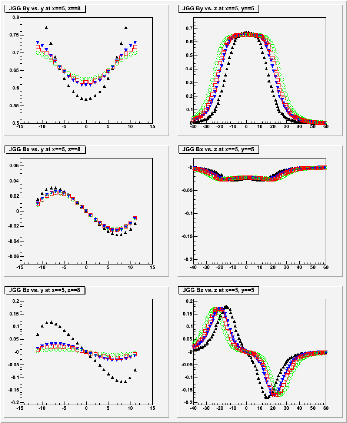
The width of the coils is given by the shape of the magnet yoke. It is hard to change. The pole pieces are 60 inches wide. This 1.46 times the width of the TPC drift volume. The length of the coils can be expanded more easily with new coils expanding symmetrically upstream and downstream of the yoke. Currently the pole pieces extend only 48 inches along the beam. This is only 74% of the length of the TPC drift volume. The effect of larger coils on field uniformity was modelled for several sizes of extensions in spring and summer of 2006MIPPNote134 . An extension of the coils by 9 inches on each end gains a significantly more uniform magnetic field and does not interfere with the placement of the detectors downstream of the JGG. The further gains for extensions larger than 9 inches are smaller. With the new coils the pole pieces will have the same size along the beam direction as the TPC drift volume. The resulting distortions will be less than 3 cm throughout the drift volume of interest, half of the distortion with the old coils. After correcting for the new distortions remaining residuals will be at most 0.5 mm. This is more than twice as good as the results with the old coil.
Besides this work on the coil geometry a lot of work was done on the detailed design of new coils. For cost reduction the new coils will be made from aluminum rather than copper. The coil conductor will have a larger cross section. Two new coils will have 360 turns. The heating calculation for the final design has been performed and found to be satisfactory. The impact on the magnet power supply and power bus was evaluated. The new coil specifications are listed in MIPP Note 137MIPPNote137 .
V.1.3 Coil replacement
The orders for aluminum for new coils and for the coil fabrication have been placed in summer 2006. The old coils have to be removed. Detectors in and upstream of the JGG will need to be moved out of the way. The new coils will be larger than the old coils. The pole pieces have to be lengthened in the beam direction to fill the resulting gap.
V.1.4 Ziptracking the new magnetic field
The magnetic field of the JGG with new coils has to be mapped. The Ziptrack system was used to map the magnetic fields of both MIPP analysis magnets before our commissioning run. We propose to upgrade the Ziptrack system with new Hall probes because the cables and connectors on the old Ziptrack Hall probes have become unreliable over time. Replacing cables and connectors on the existing Hall probes is not cost effective because the Hall probes would need to be recalibrated.
The PC currently used to control the Ziptrack and collect the data needs to be upgraded and the Ziptrack software needs to be adapted to the new hardware.
V.2 The TPC Front End Electronics Upgrade
We discuss below the details of the scheme to speed up the front-end electronics of the MIPP TPC. This is done by acquiring 1100 ALTRO/PASA chips originally designed for the ALICE experiment at the LHC. The production run for the ALICE chips is scheduled in the coming months. The STAR experiment at Brookhaven is ordering 10,000 ALTRO/PASA chips for upgrading the electronics of its TPC. MIPP plans to acquire 1100 ALTRO/PASA chips in the same chip production run thereby reducing the cost (by a factor of 5) by sharing the overhead with the STAR collaboration.
V.2.1 Brief Description of the MIPP TPC
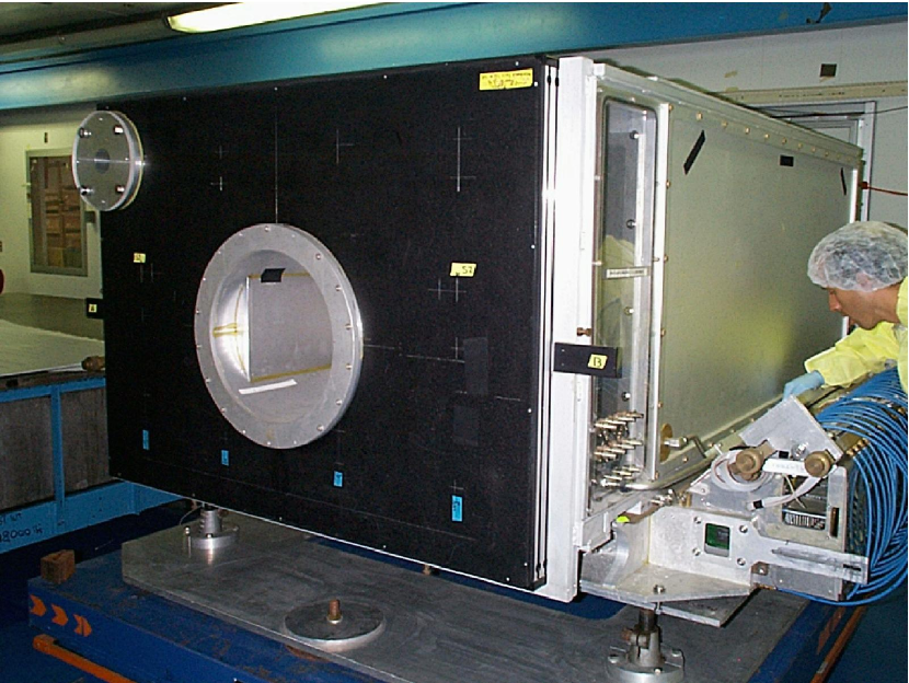
The MIPP TPC Rai90 was originally designed and used at LBNL in the EOS (E987) experiment and later at BNL (E895). The TPC encompasses an active gaseous volume of 96 cm wide by 150 cm long by 75 cm high (the drift direction), corresponding to a maximum collection time of . To minimize space charge build up, the TPC incorporates a gating grid (currently limited to a maximum pulse rate of 3 kHz) which is pulsed to allow only ionization related in time. Because of limitations in the readout electronics described below the trigger rate is presently limited to about 30 Hz. Figure 30 shows the MIPP TPC as viewed from the upstream end.
The information from the 15,360 channels in the TPC is used to determine with high precision, in three dimensions, charged particle tracks emerging from the target station mounted on the front aperture of the detector. This chamber has the ability to independently record over 3,800,000 individual data points for a single interaction event and forms the basis of the precision momenta and dE/dx measurements for each particle trajectory. The original device that was refurbished for MIPP was designed with a readout system that limited the total data acquisition rate to a maximum of 60 Hz. Redesign and updating of the TPC front end electronics, replacing the aging 20 year old components with new high density components, is projected to allow a 100 fold increase in the maximum readout rate of the detector to a theoretic limit of 3 kHz.
Currently the readout of the TPC is limited by the multiplexed serial readout system which operates on non-zero suppressed data samples for each given event. In this manner the maximum readout speed is limited to 60 Hz, due to the high channel count readout and slow (1 MHz) multiplexing/digitization system. The observed occupancy however, for a typical interaction event in the TPC is only on the order of 5% of the total channel count. This results in the possibility of greatly increasing the readout capabilities of the detector by performing the initial data filtering on board the front end electronics and reducing by at least an order of magnitude the data through-put that is currently required for a single system read. The readout can be further enhanced by improving the digitization time required for each pad row and increasing the over all parallelization of the readout system.
The design goal of the proposed electronics upgrade is to bring the speed of the readout system to 3 kHz for normal operation of the system. Operation of the system at 3 kHz requires that sustained readout of the chamber be accomplished in less than 0.3 ms. Non-uniformities in event rate induced by beam structure, restricts this rate in such a manner that the operational time for full event readout should not exceed 0.2 ms during burst operation for sustained high speed data acquisition.
The average zero suppressed data size for events as measured during the MIPP physics run was determined to be on the order of 115 kilobytes for a multi-track interaction event. The raw data rate when combined with transaction overhead results in the requirement that the output data pathway be designed to accommodate a single spill burst data rate of 575 megabytes/s. The proposed upgrade addresses this throughput via a minimum 5-way parallelization of the output data-way, resulting in a requirement of only 115megabytes/s per primary data pathway which is compatible with commercial data bus implementations.
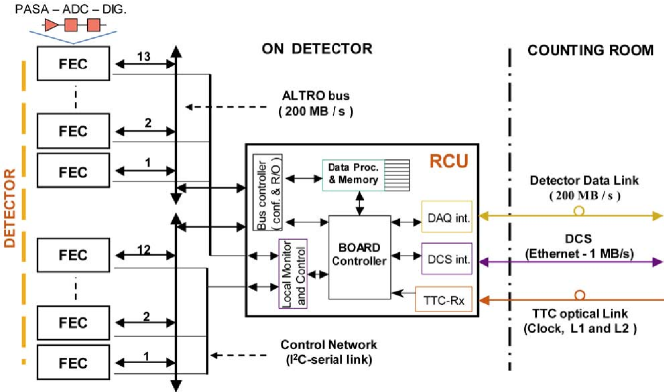
The upgrade of the TPC front end cards (FECs) to meet these requirements has been studied using a pair of custom designed ASICs that have been engineered, tested and produced for A Large Ion Collider Experiment (ALICE) collaboration at the LHC for use in their more than 570,000 channel time projection chamber. The system incorporates two separate chips, “PASA” an analog preamp/shaper and “ALTRO” a fast ADC/filter which provides event buffering, baseline corrections, signal filtering and zero suppression. The two chips are integrated in a standardized front end card with a dedicated data bus that is synchronized to the main data acquisition system via a series of readout control units (RCUs). The system has also been adopted by STAR collaboration at BNL, the BONUS at Jefferson Lab, as well as by the TOTEM experiment at CERN.
V.2.2 ALICE ASICs
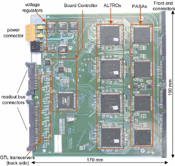
To accommodate the readout of 570,136 charge collection pads, each sampling a maximum of 1000 samples per event, the ALICE collaboration designed and engineered two custom ASICs to operate in the high rate environment of the LHC heavy ion program. The ALICE readout design, as would be incorporated into the upgrade of the MIPP TPC would replace both the analog and digital portions of the current front end electronics cards. Each of the existing 128 analog/digital electronic “sticks” would be removed and replaced in a one to one manner with an ALICE FEC ( both of which are shown in Fig. 31), redesigned to match the physical dimensions of the aluminum cold plate upon which the current electronics are mounted. Additionally the cards would be fitted to use zero insertion force (ZIF) socket compatible with the current TPC chamber connections and interlocks. This redesigned FEC follows in all other respects the electrical design and characteristics of the current CERN board layouts.

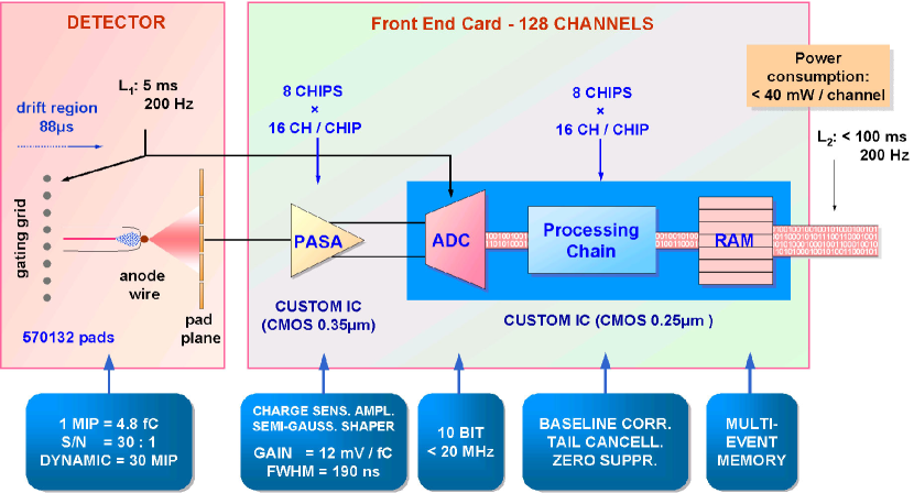
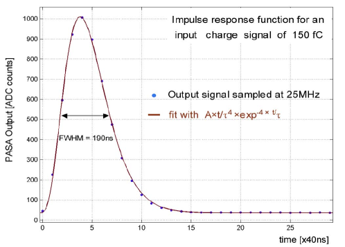
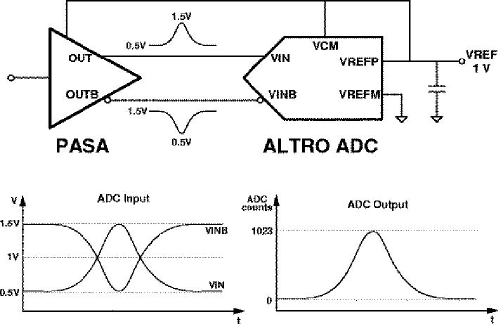
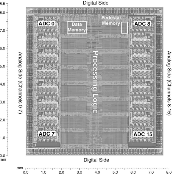
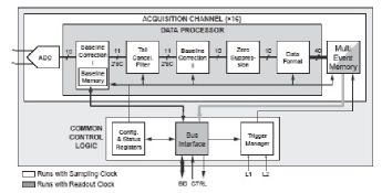
The ALICE system as shown in Fig. 32 is divided into two stages. The raw signals from the detector pad rows are first fed into a custom designed integrated circuit referred to as “PASA” which serves as the preamp and pulse shaper for each channelmota_2000 . The raw charge collected from the sample window is reshaped into a sharply peaked output distribution of width , as shown in Fig. 33, which is matched to the input requirements of the ALTRO chip for accurate digitization. Each PASA chip services 16 readout pads and is matched to the ADC inputs of the ALTRO chips shown schematically in Fig. 34 for a single digitization channel. The ALTRO ASIC as shown in Fig. 35 is a 16 way parallel system including on each channel a 10 MHz ADC, digital signal processor, and memory buffer. The operation of the chip is compatible with normal fixed-target data acquisition operation. Although the signals are sampled continuously the data is processed (pedestal subtraction, shaping and sparsification) only upon receipt of a Level 1 trigger signal. The processed data is stored in the memory buffer upon receipt of a Level 2 accept signal or otherwise discarded. The chips are controlled over a 40 bit wide “ALTRO BUS” developed at CERN subiela_2002 ieee_musa for communication with with a Readout Control Unit (RCU).
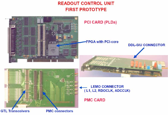
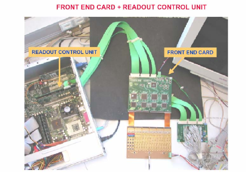
The RCU system, as shown in Fig. 36, serves as the interface between the experimental acquisition and control software and the front end cards. Each RCU is designed to interface with a set of 12 front end cards providing a single high speed data pathway for the zero suppressed event data. The protocol of the output data path is customizable and has been shown to operate both with the high speed serial link protocols developed at CERN, as well as the more common USB protocol and peripheral connection interface (PCI) to bridge the data directly into single board computer memories for further processing. Prototypes of the various RCU interface cards as shown in Fig. 37 and Fig. 38 and have been built and tested both by the ALICE and BONUS collaborations using standard PC based test stands like the one pictured in Fig. 39. The current prototyped RCUs would need no further adaptations to interface directly with the current VME signal board computer system used in the MIPP system.

Implementation of the ALICE front end electronics in the MIPP TPC requires that several additional modifications be made to match the operational needs of the existing hardware. The time window for event scanning and digitization will be reduced from 1000 samples per event to 250 samples to match the drift time over the active volume of the detector. The reduced number of samples then allows for additional segmenting of the ALTRO event buffer in such a manner that the FEC cards will be able to fully buffer 8 events at a once. To ensure that the heat load generated by the new front end boards is compatible with the existing cold plates and water cooling system, provisions have been made to operate the ALTRO bus at 20 MHz instead of the 40 MHz design frequency. These modifications are projected to both increase stability and retain the utility of as much of the existing equipment as is possible. The component requirements for the full system upgrade of the time projection chamber are listed in Table 3. The projected yield for the PASA and ALTRO wafers based upon the previous production run is estimated at 82%. When yield is included, it is estimated that 1200 raw dies would be required to obtain enough components to instrument the detector.
| Component | Channels | no. Per FEC | Total Required |
|---|---|---|---|
| Front End Circuit Board | 120 | 1 | 128 |
| ZIF Sockets | 1 | 128 | |
| Preamp/Shaper (PASA) | 16 | 8 | 960 |
| ADC/Filter/Memory (ALTRO) | 16 | 8 | 960 |
| Readout Control Units (RCU) | 1:16 | 8 | |
| Single Board VME PCs | 1 | ||
| Gigabit Network Switch | 1 |
The cost per channel for the ALTRO electronics solutions, dependent upon chip yield, is estimated at $10 per channel based upon the electronics costs for instrumenting the BONUS TPC at Jefferson lab. The total cost of the front end electronics modifications is estimated at a direct cost of $180,000 without contingency. Additional cost is incurred in the procurement of single board VME style computers for event filtering and synchronization. The single board processor is estimated to cost $4800 dependent upon final specifications and memory buffering requirements. The total direct cost of equipment for upgrading the MIPP time projection chamber is estimated at $190k without contingency.
The contract signed by CERN and Fermilab would deliver the 1100 ALTRO/PASA chips needed by this upgrade scheme to be delivered after they are tested and verified to work. Faulty chips would be replaced by CERN.
Fermilab has started the layout work for the TPC front end boards using the Altro/Pasa chips. Figure 40 shows the layout of a complete TPC stick using Altro/Pasa chips.
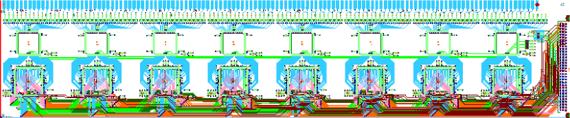
Figure 41 shows the detail of the layout for one Altro/Pasa unit.

V.3 MIPP trigger system upgrades
MIPP trigger consists of two parts. The raw beam trigger is formed by coincidence between scintillator counters (TBD and T01) placed at the entrance of the MIPP hall and just before our interaction target respectively. Particle identification is performed on the beam using the information from the beam Čerenkov system for higher energy beam and by the time of flight counters for lower energy beam. We were thus able to trigger on 6 species of beam particles ( and ). The interaction trigger in MIPP consisted of information from a scintillation counter (SCINT) placed after the target combined with information from the first drift chamber downstream of this. This interaction trigger has performed well during our physics run but its purity/efficiency suffered for lower multiplicity events due to the inability to tell apart single and multiple tracks in SCINT because of Landau tails in the pulse height distributions. It also suffered from occasional oscillatory behavior in the drift chamber. These inefficiencies will be corrected during offline analysis of the present run to obtain the correct multiplicity cross sections. The SCINT counter also introduced 0.5% interaction length, which would would result in triggers caused by interactions in the counter.
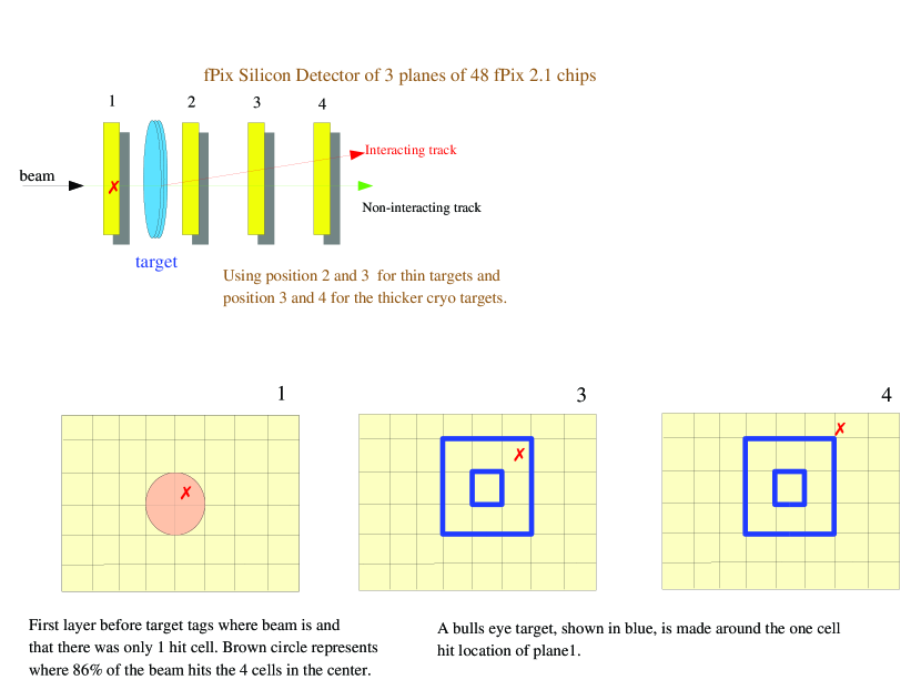
In the upgraded MIPP experiment, we propose to remedy these defects by a new interaction trigger based upon the fPix Silicon pixel detectors developed for the BTeV experiment and being proposed for the Phenix detector at BNL.
V.3.1 Interaction Trigger
There will be one Silicon pixel plane upstream of the target and two planes downstream of the target. Each layer will consist of an array of six by eight fPix chips. The pixels on each chip are 400 by 50 , with the finer segmentation in the y vertical direction. The fast chip hit signals from each fPix chip will all be independent so that it can be input to a trigger processor, but the readout of each individual chip will be coupled across the rows so that each silicon detector plane provides six rows to read out. The fast chip hit signal will be latched on the rising edge to be 50 ns wide. The fast chip hit signal will be inactive for 130 to 200 ns. With our planned 300 kHz beam rate with the beam being spread over four chips, this will not impose any substantial dead time limitations. Approximately 86% of the beam will hit four chips upstream of the target. The two planes downstream of the target will be used to form track-pointing to make sure that the interactions come from the target and not from the 300 silicon or other material.
Several different categories of triggers will be used. The first type are non-interacting beam tracks that go without interacting in our 1% target and hits are observed in a “bull’s eye” in the downstream pixel counters where we expect beam. These non-interacting beam triggers are highly pre-scaled and used for monitoring the experiment. An interaction trigger is formed when we do not have a beam track in an expected “bull’s-eye” region. This bull’s eye region is defined in a dynamic way for each beam track depending on its point of impact in the first silicon plane. The other trigger planned is based on total multiplicity of hits in the two pixel planes downstream of the target. The interaction trigger logic on the fPix signals will be performed in a custom interaction trigger board.
The trigger schematic is shown in Figure 42.
As in the original MIPP trigger system, we will keep the ability to pre-scale triggers so that we take 80% of events that have an interaction trigger with an equal amount of pions, kaons and proton interactions. The other 20% will be un-interacted beam triggers, to monitor the efficiency and performance of detector, trigger efficiency and dead time. It should be pointed out that this trigger scheme will have greater efficiency in triggering on low multiplicity events and so is of importance for the ILC tagged neutral beam events which have two charged tracks and one missing neutral.
V.3.2 MIPP Trigger Electronics
The MIPP trigger electronics will remain mostly as currently configured with some reorganization of the NIM and CAMAC crates. The main goal will be to streamline the trigger system and remove some problematic modules which have dead channels from the two years of usage during the previous run. This work consists mostly of getting partially dead modules replaced by PREP, reorganizing the current crates and incorporate the new veto wall and fPix chip hit signals as the new interaction trigger.
As in any cross section measurements we plan to take 10% of all triggers as empty targets. For the experimental operation with thin nuclear targets this will be done by taking a spill with one target, (12,000 events in a 4 second spill every 2 minutes) and the target wheel will automatically be advanced to the next target. The wheel consist of 8 slots one of which will be empty. By moving the target automatically between spills, we plan to make the most effective use of the beam and have empty target runs that reflect the beam quality backgrounds.
Table 4 gives a summary of the equipment needed for the trigger upgrade.
| Equipment | Cost |
|---|---|
| 3 Planes of fPix detectors | $87,100 |
| fPix mounting, cooling, LV, bias and PCI boards | $50,000 |
| Interaction Trigger logic board | $8,800 |
V.3.3 Trigger Tasks
The following tasks have to be performed to build the trigger system.
-
•
PPD tasks
a)Engineering support to mount fPix interaction trigger planes on a stand and position to 100 micrometers around the targetb) Trigger board that receives the 144 fast chip hit signals generates a fixed width gate based upon the rising edge of the signal. Time is about 3 months to design (4 weeks), build (2 weeks) and program (1.5 months) a FPGA board including testing.
-
•
CD tasks
a) Engineering support for the fPix chips readout into DAQ and using the fast chip hit signals for interaction triggering.
b) PREP to replace partially dead modules and provide new modules for the new elements in the trigger. -
•
MIPP tasks
a) Programming of the Physics triggers in FPGA trigger board.
b) 4 months of a physicist to streamline the trigger system, replace partially dead modules and incorporate the new veto wall and fPix interaction trigger into the DAQ trigger system. Two weeks of beam time will be needed to understand and fine tune this system.
V.4 Upgrade for Chamber Readout Electronics
Currently the drift chambers are read out through pre-amplifiers and discriminators inherited from the E690 experiment that use CAMAC TDCs.
The large MWPC’s are read out through RMH electronics that have not been supported for several years.
This system was maintainable through the first MIPP physics run and produced good data from three beam chambers and six tracking chambers downstream of the experimental target. However, there are several issues that need to be resolved.
We managed to keep the RMH system in working order up to now using spares. However, it is not possible to guarantee that this readout system will work through another run.
The readout of the CAMAC TDCs currently uses the CES CBD8210. This system is obsolete and not maintainable any more. CAMAC hardware in general is becoming less well supported. Currently the TDCs are read out without the use of DMA. The current readout system could perhaps be upgraded to transfer data in DMA mode. A new solution for the CAMAC readout and the change to DMA transfer would likely be sufficient to obtain a readout time as needed for operation at 3000 Hz. However, a new readout will provide much more flexibility at only incrementally higher cost.
The existing system uses a large number of high current low voltage power supplies. Each drift chamber uses two 5 V and one 10 V supply. All of these supplies are aging and several have failed during the past run resulting in minor downtimes.
The current system dissipates a large amount of heat in the area of the experiment between the two analysis magnets. This has caused significant problems with air conditioning in MC7. The air conditioning itself is an old system. With the present heat load the air conditioning system in MC7 would need to be upgraded.
In preparation for the first MIPP physics, new electronics for the RICH detector readout were built. The RICH readout uses front end boards that read out the RICH PMT’s and send data to VME readout boards. This solution has been working well and essentially the same readout board will be used for the new TPC electronics. This readout can be adapted for all chambers.


For the new readout, we propose to build new pre-amp cards with 8 and 16 channels per card for the drift chambers and MWPC’s, respectively (see figure 43). These cards will be mounted on the chambers in the same way that preamp cards are mounted presently. Several of these daughter cards will connect to 32 channel TDC front end cards as shown schematically in figure 44. These cards will be based on the RICH front end cards. The RICH cards provide a latch for each channel whereas the new chamber cards will use TDCs. Each card will hold enough memory to buffer data for an entire 4 second slow spill.
The Chamber front end cards will be daisy-chained (see Figure 45) onto a total of five VME readout cards in the same way that multiple RICH front end cards are read out.
The total cost for the new chamber readout electronics is estimated at $121k for material and $29k for labor. The labor cost is low due to the simple design of the new readout based closely on existing electronics designed by the same engineers. The largest material costs are $56k for 1100 daughter cards and $49k+$7.5k for 325 front end TDC cards and mounting structures/mechanical protection.
A detailed list of tasks is included in the Gantt chart.
V.5 Time of Flight, T0, and threshold Čerenkov Readout
The current Time of Flight (ToF) readout uses LeCroy 2229 CAMAC TDCs. The 2229 modules have a long conversion time when used in full range mode as is desired by the MIPP experiment. The Time of Flight signals are also read out with CAMAC 4300 ADCs needed for slew corrections on the TDC signals. These ADCs are FERA modules, but are currently read out through the CAMAC backplane.
Long delay cables are used in order to receive a trigger for the common TDC start and ADC gate. These ribbon cable delays are sensitive to the environmental temperature. This causes fluctuations in the timing response that are large compared to the timing resolution needed for ToF particle identification. Although much work is being done to correct for these fluctuations in offline analysis, a change in the readout to eliminate these temperature dependent variations will make the ToF system more robust and significantly simplify the offline analysis, reducing both time and man-power needed for data analysis.
The threshold Čerenkov (CKOV) detector is read out through ADCs and multi hit TDCs. It has 96 channels. The current readout uses CAMAC hardware.
The T0 detectors in the beamline provide the beam definition for the trigger and the timing mark of the interaction in the target. They are also used at low beam momentum for beam particle identification. A total of three scintillators in the beam line is read out with 12 photomultiplier tubes. With proposed modifications to the trigger we would need to add delay to the signals of the T0 system. This would degrade timing resolution.
If the CAMAC readout was to be maintained we would need to obtain new readout for four CAMAC crates for the ToF readout and for two CAMAC crates for the CKOV readout. The currently used CES CBD 8210 module is no longer maintainable. The new solution for CAMAC readout is the Hytec1365 module. It provides readout for one CAMAC crate, but does not allow to put multiple crates onto a CAMAC branch. Thus the experiment would need to purchase six of the Hytec1365 modules to read out the ToF and CKOV. These modules by themselves would cost $30k. The total upgraded readout system for these detectors would be more expensive.
Instead we propose to build a new readout for these detectors. Again the back-end will be provided by the VME readout cards that are also used by the TPC and Chamber readouts. The front end boards will be similar to the front end cards used in the RICH and proposed for the Chamber readout with the difference that ToF and CKOV need ADC readout and the ToF needs high resolution TDC readout.
Front end boards with the TripT chip (also used by the MINERA experiment) and a high resolution TDC chip (the TDC-GPX chip from ACAM GmbH, also used by LHC-b) will provide 30 ps timing resolution for the ToF (better than the 2229 currently used) and multihit capability needed for the CKOV. The TDC-GPX chip can be operated in different modes. The mode with 30 ps resolution and 2 channels per chip fits the needs of the ToF while coarser resolution with 8 channels per chip reduces cost for the CKOV. The new electronics will be able to buffer hits. The delay cable on the ToF can be eliminated.
Design of the front end cards for the ToF and CKOV is expected to not pose significant challenges. The TripT chip and the analog part of the circuit will essentially be copied from a MINERA design and the TDC-GPX chip is entirely digital.
The total cost of the new readout for the ToF and CKOV is estimated at $34k. The production cost is small because the total number of channels is small (106 ToF + 12 T0 + 96 CKOV + spares). The design cost is small because the system uses components that are common to other systems.
V.6 Calorimeter Readout Upgrade
The MIPP EM calorimeter consists of 640 proportional tube channels. Every event has 50% of these channels above pedestal mean. Currently there are 160 ADC channels reading out four times for each event into a data buffer. This takes 800 per event.
The readout time needs to be reduced to significantly below 300 in the upgrade. We propose to install a system of four crates of FERA ADCs to read out the EM calorimeter. Two crates of FERA ADCs each will be read out on the front bus by two FERA drivers that sparsify the data. The data above pedestal is then read through the CAMAC back plane using two Hytec CAMAC controllers with buffer memory that send the data to a PC through ethernet.
Setting the pedestal subtraction to the pedestal mean plus 2 or 3 sigma of its width will reduce the number of channels with data further. With 80 words of data per CAMAC crate per event and DMA CAMAC data transfer we expect to achieve 40 readout time per event.
The cost for this upgrade is driven by the cost for the two Hytec1365 CAMAC readout controllers.
V.7 Upgrades to the Online Data Acquisition System
The MIPP DAQ system used in the 2004 to 2006 runs was originally designed and coded in 2003. It utilized components that were readily available at the time such as the CES CBD8210 CAMAC branch drivers, six VME power PCs and assorted other electronics. The DAQ system itself used the Fermilab CD event builder of that time (r2dm) which during the run constrained our system to remain at RedHat Linux 7.3 operating system (due to ACE/ITC). The CBD8210 CAMAC branch driver can no longer be maintained nor are the old power PCs capable of being upgraded to the newer operating systems. Hence the DAQ system for the upgraded MIPP experiment is in need of a major overhaul. This is important not only for the larger physics data set expected in the upgraded MIPP experiment which is 100 times more demanding at 3 kHz than the old system running at 30 Hz, but also in sight of the long term use of the MIPP experiment when eventually the calorimeters of the MIPP experiment will be replaced by ILC test calorimeters for tagged neutral beam studies. So having a DAQ system whose electronics and operating systems can be maintained through the year 2010 is of importance.
From May to September 2006 a group of MIPP physicists and the Fermilab Computing Division met weekly to determine the route that this MIPP DAQ upgrade should proceed. It also involved discussions with the PPD electronic engineers who are building new electronics for the TPC and wire chamber readout. The new DAQ can be broken up into four groups: CAMAC, VME, fPix and computers. In addition there are requirements that we wish to address for local data storage, long term data storage for Physics analysis, network infrastructure and long term data analysis CPU needs.
The DAQ hardware upgrades consist of replacing the CAMAC Crate controllers and old Power PC’s with a newer version, and interfacing the new equipment being built. Most of the work on the DAQ upgrade is in software code development for the CAMAC and the newer PowerPC’s. We will continue to use the DAQ user interface and run control code from the existing MIPP DAQ system. The experiment will continue to maintain these parts of the code and the code specific to the readout of all detector systems. We are asking the Computing Division for support on three specific tasks only. These tasks are the ethernet communication of the Hytec module, operating system support on the PCs, and upgrade of the event builder.
V.7.1 The CAMAC systems
It is economical to keep some of the electronics in the CAMAC system which includes ADC, TDC, and assorted trigger electronics modules. The two CBD8210 CAMAC branch drivers control 12 CAMAC crates in the old DAQ system. The CBD8210 module cannot be maintained further and six options were available to us for replacement. We concluded that the Hytec CAMAC crate controller 1365v4 is the CAMAC crate controller of choice. It has several advantages: it will be maintained through 2010, it comes with enough on-board memory to buffer an entire spill for a fully loaded CAMAC crate, has a data transfer rate that matches our needs, has an event time stamp feature for each event and the upgraded v5 features with a firmware upgrade will have pedestal subtraction sparsification features that we requested. Each 1365 crate controller is read out through a fast 100 Mbit ethernet link to the central DAQ computers independently.
The wire chamber readout in the upgraded MIPP experiment will be changed to new electronics that does not involve CAMAC. The Plastic Ball will be added as a recoil detector in the upgrade. It currently has a CAMAC based readout that will be upgraded to FERA ADC or a dedicated system using the BTeV qie chips. The new readout will contain a total of four to seven CAMAC crates read out through the Hytec controllers.
V.7.2 The VME systems
Currently MIPP has the RICH PMT readout in a VME crate shared with the power PC and the old CBD8210 CAMAC branch driver. The RICH PMT readout board will remain and additional VME modules designed by the PPD electronic shop for TPC and wire chambers will be added. Currently the six power PC’s (four for the old TPC electronics and two for the CAMAC and RICH readout) will be replaced by two new Power PC 5500’s. There is no need to upgrade the old RICH readout boards except to read them out on an event by event basis during the spill with the new Power PC 5500. The new TPC and wire chamber readout will have event buffers for the spill so that at the end of each spill the sparsified data will be sent by the data transfer process of VME modules to the the DAQ central computer with the Power PC’s processing the data.
V.7.3 fPix readout
A new tracking silicon detector system is planned for the target region. These will be used as part of the new interaction trigger system which is described in the trigger section, but its readout will need a dedicated PC computer with an extended PCI bus that can handle 18 PCI cards, one for each row of fPix chips of the 3 silicon planes. During the spill the dedicated fPix computer will constantly readout each event into a local memory or a disk file. This will then be transferred at the end of the spill to the central DAQ computer.
V.7.4 DAQ system Computer
The central DAQ computer will receive and assemble event data and copy it to tape storage. The computer must be fast enough to be able to readout the two Power PC 5500 with TPC and wire chamber data, the four CAMAC crate interfaces, and the fPix computer. This will be done through an upgraded event builder.
The expected data rate is 1 Gbyte per spill. This must be transfered and handled by the computers before the next spill, i.e. within 56 seconds. The nominal rate is that MIPP will get a 4.0 second spill every two minutes, but during some fraction of data taking the system must be able to handle one spill every minute. All processors, (Power PC 5500’s and Hytec 1365v5’s) have Gigabit and 100 Megabit fast ethernet ports and should be able to handle the highest rate expected in only a few seconds to get the data to the main DAQ computer and enable out-of-spill calibration and monitoring data acquisition. The main DAQ computer should be able to process the spill through the event builder in the remaining 56 seconds and store it onto a mirrored disk system. The local disk system needs to have a capacity of 1 TB to provide local storage for day of data. The local storage will allow continued data taking in case of network problems between the experiment and the tape backup at FCC.
This computer also has to provide access to the data for online monitoring. This is presently done through a cross mounted disk using NFS. Another model would be for the DAQ software to send a data stream to the monitoring PC through the network, thus avoiding double disk access for monitoring.
A separate PC will run the graphical human interface to set up run conditions, start and stop runs, perform pedestal runs, etc. For the main DAQ computer a dual CPU system with a 3 GHz processor with a high speed bus can provide sufficient computing power to support event building and data transfer to Feynman and the monitoring PC.
V.7.5 Monitoring Computer
In order to reliably monitor data quality, two approaches are used. Summary histograms with event statistics provide data on dead/hot channels and similar statistics for all events in the last spill which will be displayed and compared to reference plots for presentation to the shift operator on five display monitors. The computer will automatically do a comparison of these distributions and audio alarms will be provided when there is an obvious problem. Also a fraction of the events have to be fully reconstructed and displayed constantly on a monitor for full event data validation. This track reconstruction is CPU intensive but we would expect that 10 events out of the 10000 taken each spill need to be fully reconstructed to monitor physics quality.
This set of tasks is best handled by a dual CPU computer that receives a copy of the data stream. The system also will need six monitors that the computer can display the data on at the end of each spill.
V.7.6 Data transfer to ENSTORE, Data storage in Feynman Computer center and Offline analysis needs
Our average event size is 100 kBytes. The 3 kHz event rate expected in the upgraded MIPP experiment results in 1.2 Gbytes of data per spill. With 58% accelerator uptime we will receive 420 spills per day and record 500 Gbytes of data per day. We expect to transfer this data to the Feynman Computing Center ENSTORE tape robot continuously during the day. A 6 Mbytes/second transfer rate through the site network and into ENSTORE is needed. The CDF and DØ experiments currently obtain 30 to 60 Mbytes/second. Thus the existing ENSTORE system should be sufficient. For offline storage and CPU needs, please see the discussion in the section entitled “Proposed Run Plan”. See table 5 for a summary of the DAQ equipment costs. See Figure 47 for a schematic of the proposed MIPP data acquisition system.
| Equipment | breakdown | Cost |
|---|---|---|
| 2 Power PC 5500 | 2x$4800 | $ 9600 |
| 5 Hytec 1365v5 | 4x$4634 + $2316 site license + spare $4634 | $33486 |
| 2 3 GHz PC | 2x$2759 | $ 5518 |
| 2 1 Tbyte disk | 2x$1021 | $2042 |
| 6 write only displays | 6x$189 + 6x$36 driver boards | $1350 |
| 1 PC for fPix | $1778 | $1778 |
| 2 13 slot PCI extender | $1999 | $3998 |
| Total | $57472 |
V.7.7 DAQ Task Summary
The MIPP/CD DAQ group has identified the following tasks as being central to the upgrade. In their initial discussion, the following was felt to be an optimal division of tasks between the experiment and the computing division.
-
•
(CD task) Update event builder for the new kernel and operating system (Estimate 6 weeks of 1 person full time.)
-
•
(CD task) Readout package for the fast ethernet of the new Hytec 1365v5 CAMAC crate controllers (2 Weeks)
-
•
(CD task) Get the Linux kernel operating on the two new Power PC 5500 (Estimate 8 weeks of 1 person full time in two blocks of 4 weeks, with a spare 2 weeks at the end)
-
•
(MIPP task) Provide all the CAMAC commands to read out all the CAMAC modules. (Estimate 1 month)
-
•
(MIPP task) Modify the DAQ for the new TPC(12 weeks) and wire chamber readout modules (4 weeks), CKOV, ToF (Estimate 4 weeks)
-
•
(MIPP task) Calorimeter FERA ADC readout (5 weeks)
-
•
(MIPP task) Modify the Event Monitor(2 weeks)
-
•
(PREP task) Test the electronics modules being re-used (4 Weeks)
-
•
(PREP task) Maintain all associated CAMAC, NIM and VME modules.
-
•
(PPD task) Maintain custom electronics built for RICH, TPC, wire chambers, Interaction Trigger and TOF-TDC.
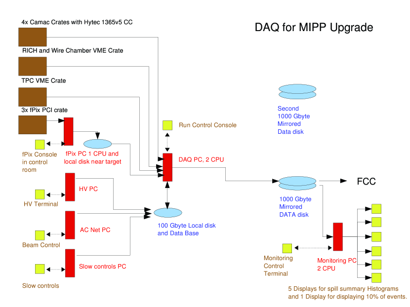
We foresee a 6 month commissioning run during which work will continue to integrate the new pieces of software together. See section on “Proposed Run Plan” for a discussion of these issues.
V.8 Cryogenic Target Upgrade
V.8.1 Modifications to the Cryo-target
The cryogenic target and refrigeration system built for MIPP worked well during the commissioning and physics run. MIPP has acquired over 5 million events on liquid hydrogen. There are, however, some design changes we would like to perform The target volume is contained in a vacuum space connected to the cryogenic system through a transfer line. The beam has to travel through part of this transfer line to get to the target. The inner diameter of the transfer line, based on the E690 design is currently small. A very small fraction of the beam particles in the tail hit the transfer line (with the exact fraction depending on the beam tune) and causes triggers. This causes a large background none-the-less because the experimental target is 1% of an interaction length thin, while beam particles encounter a much larger fraction of an interaction length if they hit the transfer line. The existing transfer line also is not compatible with the Plastic Ball detector that we plan to install as a recoil detector just upstream of the TPC to cover the hemisphere upstream of the target. In addition to the new transfer line the mounting structure of the refrigerator on the JGG magnet yoke will have to be modified to be compatible with the extended JGG coils and the Plastic Ball. ] These modifications will cost $51k in material and labor.
V.8.2 Modifications to operate with cryogenic Nitrogen
The cryogenic target system will need to be modified to allow for cryogenic Nitrogen operation. Liquid nitrogen is heavier than liquid hydrogen or deuterium and it is warmer. Thus a new target flask will have to be designed and fabricated and the target control system will have to be expanded to allow control at liquid nitrogen temperature. The cost for material and labor for this upgrade will be $33k. This target can also be filled with liquid Argon.
V.8.3 Cryocooler
One component of the cryogenic target system is the cryocooler. It has been working up to now. However, it is old and we do not have a spare. We have identified the cryocooler as a single point of failure that could result in significant downtime to the experiment. A new spare cryocooler will cost $40k. Additional parts and labor to make the new cryocooler compatible with the existing target will cost $20k.
V.9 Gas System and Slow Control Upgrades
The detectors in the MIPP experiment use a variety of gases and gas mixtures. These are provided by an extensive gas system. Overall this gas system has been working well. However, there are some aspects to the system that we propose to improve further.
V.9.1 Methylal bath system
The drift chambers operate on a mixture of Argon, Isobutane, and a small fraction of Methylal. The Methylal is added by flowing a fraction of the mix of the other two gases through a bubbler in a liquid Methylal bath.
The Methylal refrigerator on the drift chamber gas mixing system requires frequent maintenance due to water ice building up. It also needs to be filled frequently due to its small reservoir size. We propose to upgrade the Methylal refrigerator to a system that fills automatically from a larger reservoir and works with less maintenance. This will make the system more reliable and also reduce contact of shift personal with the Methylal, thus increasing safety. We estimate the cost for this task at $12k.
V.9.2 RICH Vessel Fill Automation
The RICH vessel is filled with CO2 at slightly above atmospheric pressure. It was designed to be a gas tight vessel to keep constant gas density in the radiator volume. The vessel has a small leak that could not be found. This is not a problem because the changes in gas density can be computed from temperature and pressure of the gas, both of which get monitored electronically. However, the system needs to be maintained above atmospheric pressure to avoid oxygen contamination of the CO2. This requires manual intervention weekly to bi-weekly depending on the weather. In order to minimize the pressure fluctuations and hence the corrections to the data we propose to install an automated CO2 fill system. This system will cost $8k in material and labor to implement.
V.9.3 Other Gas Upgrade
The TPC is operating with P10 gas, a mixture of 10% methane in Argon. We developed a mixing system for this gas mixture. When we had problems with breaking wires in the TPC we switched to a backup system of premixed P10 cylinders. The existing system was designed as a backup to the mixing system rather than a primary supply system. A cylinder lasts only two days. The bottle pressure is not monitored electronically. The overhead for bottle changes and gas orders was significant. The system allows for the introduction of air contamination into the P10 during bottle changes that could result in broken wires. We propose to upgrade the P10 system to be supplied from a semitrailer.
The beam Čerenkov detectors (BCkov) use vacuum pumps to run below atmospheric pressure. The vacuum pumps can fail and in worst case introduce oil into the BCkov vessels. With upgraded vacuum instrumentation any such failure can be detected early. This will increase system reliability and significantly reduce the chance of a failure that would result in a long downtime.
V.9.4 Slow Controls Upgrades
The temperature in the experimental Hall is currently being monitored in several places. Due to the sensitivity of some of the detectors to temperature we propose to add more temperature probes throughout the experimental hall and especially in the region around the time of flight detector.
The threshold Čerenkov detector pressure sensors need to be replaced before the next physics run. These and other sensors need to be recalibrated.
Control and monitoring of new components for the gas system and cryogenic target require additional slow control infrastructure. These upgrades will cost $34k.
V.10 Photomultiplier Tubes for RICH and Čerenkov detectors
The RICH detector images Čerenkov rings with an array of 96 columns of 32 half-inch diameter photomultiplier tubes. Currently 15 columns are instrumented with 12 stage Hamamatsu R560 PMT’s and 52.5 columns utilize 10 stage FEU60 PMT’s. The remaining 912 positions in the RICH are not instrumented due to the loss of PMT’s in a fire during commissioning of the MIPP experiment in Spring of 2004. The remaining PMT’s were distributed over the RICH array. With the present configuration, the RICH performed well during the MIPP physics run in 2005/2006. However, rings with a small diameter from particles near the Čerenkov threshold will be fit with better precision and accuracy if the readout is instrumented completely. The 12 stage PMT’s provide a better sensitivity for single photons than the 10 stage PMT’s.
The threshold Čerenkov detector provides particle identification for particles with a momentum close to 10 GeV/c. It contains 96 cells, each read out with a two inch diameter PMT. Seven of these 96 PMT’s need to be replaced to obtain a fully working Čerenkov detector.
V.11 The Plastic Ball Recoil Detector
The Plastic Ball detector was originally built at GSI, Darmstadt to study high multiplicity heavy ion collision events for the BEVALAC experiment at LBNL. It then moved to CERN to be in the WA80 experiment in the early 80’s pball . After the completion of the CERN-SPS heavy-ion experiment, WA98, the plastic ball moved to KVI, Gröningen, Netherlands. KVI have informed us that it is available for use at Fermilab, having finished its physics run at KVI. The GSI, Darmstadt group is interested in measuring antiproton cross sections using the upgraded MIPP spectrometer as this will enable them to better design the PANDA panda detector.
The fully configured plastic ball consists of 815 “phoswich” modules, one of which is shown schematically in Figure 48. The module consists of a scinitillator sandwiched to a plastic scintillator, both of which are readout with a single photomultiplier tube. The photomultiplier signal is measured using two gates with different widths. Light from is slow (1250 ns gate) and that from the plastic scintillator is fast (250 ns gate). The fast gate measures the plastic scintillator light only and the slow gate measures both the plastic scintillator and the light. The charged particles deposit energy in both layers where as the neutral particles such as neutrons deposit energy in the hydrogen rich plastic scintillator.
]

Figure 49 shows the identification of particles using the plastic ball by comparing the two signals. One can see the separation between the proton signal which is seen in both scintillator layers where as the neutral signal is seen only in the plastic scintillator. The neutrons and photons are distinguished further by time-of-flight.

Figure 50 shows the full plastic ball detector as configured at KVI. Figure 51 shows a schematic of 340 phoswich modules arranged as a hemisphere. This is similar to the configuration we would use in MIPP, with the hemisphere covering the target upstream of the TPC.
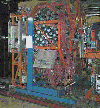
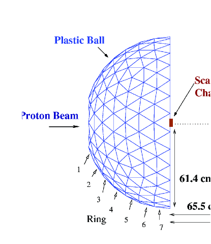
V.11.1 Transportation to Fermilab and Integration into MIPP
The intention of the GSI physicists to take part in the MIPP upgrade has only been communicated to us recently and we have not had time to design the mounting of the Plastic Ball hemisphere into MIPP. We have estimated a cost figure to do this, after talking to Fermilab engineers. GSI is in the process of assigning manpower and resources to take part in MIPP upgrade and the responsibilities will become clear at that point. The Plastic Ball detector has to be mounted in a removable fashion such that the TPC may be repaired. During NuMI target running, the Plastic Ball has to be removed from the beamline as well, since the NuMI charged tracks produced at the upstream end of the long target need to enter the TPC without encountering the Plastic Ball.
V.12 Modifications to the beam line
We propose to add low-current power supplies (Lambda- Genesis) as in M-test to run our beamline in the low momentum mode. During low momentum running, we will switch from the regular power supplies to these new ones for all the magnets in the secondary beamline. In addition, we plan to add Hall probes to each magnet to monitor the field to avoid hysteresis effects due to iron yoke residual fields to ensure that each magnet is set to the correct field appropriate for the particular beam momentum setting.
V.13 Beam Veto upgrade
In the first MIPP physics run some of the triggered events, especially at low beam momentum, have beam halo and spray particles hitting the experiment in coincidence with events of interest. The beam background particles can be separated from the events of interest when they are significantly out of time with the triggered event. But additional tracks within several 100 ns cannot always be separated from the primary event vertex in the TPC. ADC gates of other detectors in the experiment are 400 ns long. The energy deposit of background inside this window cannot be distinguished from the event signals.
The experiment is currently using a beam veto counter to inhibit the trigger when spray is present. However, this counter covers only an area around the beam of approximately . In the upgrade the experiment will read out at a rate of approximately 100 times the rate of the first run. Thus the beam intensity has to increase by a similar factor. The beam backgrounds will also increase.
We propose to expand the beam veto counter into a veto wall that will cover the area of the TPC and the proposed recoil detector. This is an area of . The signals from spray particles need to be collected in time for the trigger formation. An array of six 10 inch wide fast plastic scintillator paddles with light attenuation 100 cm will satisfy these requirements. The Rexon RP420 scintillator is a good inexpensive choice. For reliable light detection, each paddle will be read out with photomultiplier tubes on each end. The 12 signals will be latched and processed by the upgraded trigger electronics to form the trigger inhibit signal. High Voltage for the PMT’s will be provided through the existing LeCroy 1440 HV system.
V.14 Rewinding the TPC
The TPC contains three planes of wires. Charged particles ionize the P10 gas inside the TPC drift volume. Ions drift up to the solid cathode at the top of the drift volume. The cathode is at -10 kV. Electrons drift down to the ground plane of wires. Just above the ground plane is a plane of wires used to gate the TPC. This gating grid is transparent to the drifting charges when all of its wires are at the surrounding potential . Outside the gate window half of the wires in this plane are put at V and alternate with the other half of wires at V so that drifting electrons terminate in the gating grid wires. When the grid is gated, electrons drift through the gating grid and through the ground plane into the amplification region. Anode wires at +1250 V form the third plane of wires. They are just below the ground plane to create a large gradient in the amplification region. Drift electrons get multiplied in this region and terminate on the anode wires. They create image charges on the TPC pad plane just below the anode wire plane. These pads are read out by the TPC electronics. The anode wire plane actually consists of anode wires alternating with field shaping wires at ground potential.
During commissioning for the first MIPP physics run several wires in each of the wire planes broke. The TPC was opened multiple times and broken wires were carefully extracted. Figure 52 shows a section of wires during the repair. The wires broke due to contaminations in the gas. All wires were exposed to this gas. Some of the anode HV sections can not be operated at the full 1250 V. This results in gaps in sensitivity in the TPC. Due to the mounting of the wire planes it is not possible to replace anode wires without removal of the two upper wire planes.
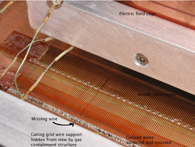
We propose to replace the wires in all planes. Lab 6 at Fermilab has a facility that can be used to wind wire onto construction frames and then transfer the wires onto the TPC wire support structures. The TPC wires are mounted in sections onto supports. These supports are not designed to hold the wire tension unless they are mounted in the TPC or on transfer frames. Frames and transfer hardware handling of the TPC wire planes need to be designed and built. The TPC wires need to be removed and the frames cleaned. Then new wires can be places on the existing mounting.supports.
This work is similar to projects previously performed at lab 6. The only less familiar aspect involves placement of two different kinds of wires onto the anode frame to get alternating anode and field shaping wires with the correct spacing. The expertise for this job exists at Fermilab.
The cost for this project is approximately $16k in material and labor.
V.15 Wire Chamber repairs
MIPP uses six large wire chambers and three smaller beam chambers. The high voltage on one of the drift chambers (DC4) started to trip frequently during the last weeks of the first MIPP physics run. One of the MWPCs has a defect that causes two of the four planes to be inoperational.
A spare MWPC is now in lab6. We refurbished it during the last run. We propose to exchange the broken MWPC with the spare and repair it. We also propose to diagnose the reason for the DC4 HV trips and repair this chamber. Both types of chamber have been repaired by MIPP physicists before. All necessary hardware exists. The cost for this project is approximately $5k.
VI Cost and Schedule
VI.1 Cost estimate of the MIPP Upgrade
The MIPP upgrade project cost is shown in detail in table 6. The total cost for all tasks including non-Fermilab contributions and labor is $2 million.
![[Uncaptioned image]](/html/hep-ex/0609057/assets/x66.png)
The most essential tasks for a successful run are the JGG repair, detector readout upgrades, and DAQ upgrades. These add to M&S costs of approximately $715,000. Also important for the success of the project are the improvements to the detector hardware, especially the cryogenic target, the trigger system, and the enhanced beam veto wall and recoil detector.
The JGG coil replacement and TPC readout electronics upgrade are the two tasks with the largest costs. These costs and the schedules for these tasks have been estimated in great detail. The orders for new JGG coils and for the chips for the TPC front end electronics have been placed.
VI.2 Schedule
The schedule for all upgrade tasks is shown in the Gantt chart in figure 53. The critical tasks in the timeline are the development, fabrication, and testing of TPC readout electronics and the integration into the upgraded DAQ system. Replacement of the JGG coils on schedule is also critical because many other tasks cannot proceed until the JGG coils are in place and the Ziptrack is finished and removed from MC7. The new TPC electronics will be operational at the end of January 2008. All other tasks can be finished on or before this date.
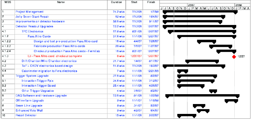
The project contains more than 450 tasks. The WBS is shown at summary level in the figure in this document. The full Gantt chart and cost and resource usage plots are available in a separate document.
VII Proposed Run Plan
We feel we will need a commissioning run lasting 6 months to debug and integrate the various components in the experiment. With the detector running at 3 kHz, we can generate a large quantity of data very quickly. After the commissioning, we propose a three stage run plan designed to use the data obtained in an optimal fashion. During the first phase we plan to acquire 110 million events as detailed in table 7. We propose to include 12 nuclei that are most commonly encountered in calorimetry in this list. This data sample is a factor of 6 larger than what we have acquired so far in MIPP and would require 11 Terabyte of storage space to hold the raw data and approximately 3-5 times that to store the reconstructed data, with tracks and particle ID. If one were to keep the offline turn-around time to be similar to what we have currently in MIPP, we would like a farm size of 600 nodes of today’s node speed. In 2 years time, the node speeds will have become faster.
| Target | Number of Events | Running Time | Physics Need |
|---|---|---|---|
| (Millions) | (Days) | Group | |
| NuMI Low Energy target | 10 | 2 | MINOS, MINERA |
| NuMI Medium Energy Target | 10 | 2 | MINERA, NOA |
| Liquid Hydrogen | 20 | 4 | QCD, PANDA, DUBNA |
| Liquid Nitrogen | 10 | 2 | ICE CUBE |
| 12 Nuclei | Nuclear Physics & | ||
| ,Be,C,Al,Si,Hg,Fe,Ni,Cu,Zn,W,Pb | 60 | 12 | Hadronic Showers |
| Total Events | 110 | 22 | |
| Raw Storage | 11 TBytes | ||
| Processed Storage | 55 TBytes |
| Target | Number of Events | Running Time | Physics Need |
| (Millions) | (Days) | Group | |
| 18 Nuclei | Nuclear Physics | ||
| Li,B,,Mg,P,S,Ar,K,Ca | Nuclear Physics & | ||
| Ni,Nb,Ag,Sn,Pt,Au,Pb,Bi,U | 90 | 18 | Hadronic Showers |
| 10 Nuclei B-list | Nuclear Physics & | ||
| Na,Ti,V, Cr,Mn,Mo,I, Cd, Cs, Ba | 50 | 10 | Hadronic Showers |
| Total Events | 140 | 28 | |
| Raw Storage | 14 TBytes | ||
| Processed Storage | 70 TBytes |
During phase 2, we plan to complete the remaining 18 nuclei of the A-List, as detailed in the section on hadronic shower simulation and then proceed with the B-list if there is need. The second phase of running is detailed in table 8.
Before we go to phase 3, it is possible that additional running time is requested for the missing baryons search depending on the outcome of the analyses performed on the hydrogen data taken in phase 1.
During phase 3, we plan to go into the tagged neutral mode, where we run the liquid hydrogen target and allow the ILC calorimetry to run simultaneously in place of the MIPP calorimeter. This mode is shown in table 9. The running times for this will be dictated by the schedule of the ILC calorimetry test modules available then.
| Target | Number of Events | Running Time | Physics Need |
| (Millions) | (Days) | Group | |
| Liquid | 5 million events/day | As needed | ILC Tagged neutral beams |
It should be pointed out that the running times in Tables 7 and 8 are the actual amount of beam on live times. They do not include the time taken to setup the various target conditions, target cool-down times (in case of cryo-targets) or calibration runs (such as magnetic field off runs, target empty runs). These end effects could become quite significant when computing the actual duration of a particular phase.
The upgrade factor of 100 in DAQ speed can be thought of as permitting the acquisition of 10 times the data we acquired so far in 10 times less time. This results in considerable savings in machine time and manpower to keep the experiment operational. The quality of data acquired will be considerably improved over what we had in the first run, due to improvements in triggering, recoil detector and Jolly Green Giant field quality.
VIII Conclusions
We have proposed a cost-effective upgrade solution to the MIPP DAQ that will make MIPP a powerful spectrometer with hitherto unprecedented particle identification and acceptance. Such a spectrometer will be capable of improving our understanding of hadronic shower simulations significantly and will help a large number of experiments which have non-perturbative QCD processes as a signal or a background understand their systematics better. Particularly helped will be Fermilab neutrino experiments (MINOS, MINERA and NOA) as well as the cosmic ray experiments such as ICE CUBE. MIPP will also acquire much wanted data to help the PANDA collaboration and also test various hypotheses in non-perturbative QCD (Inclusive scaling relations, missing baryon resonances and multiplicity enhancements at high multiplicity). In addition, it can also serve as a source of tagged neutral beams to help the international linear collider detector community to benchmark the particle flow algorithm.
References
- (1) The main MIPP web page is at http://ppd.fnal.gov/experiments/e907/. Information on the MIPP collaboration may be found using links there.
- (2) The MIPP proposal and Addendum to the proposal may be found at http://ppd.fnal.gov/experiments/e907/Proposal/E907_Proposal.html
- (3) The Time of Flight detector was fabricated by MIPP and consists of an array of 10 cm10 cm scintillators and 5 cm5 cm scintillators. See http://ppd.fnal.gov/experiments/e907/TOF/TOF.html for a detailed description of the detector.
- (4) The multi-cell Čerenkov detector was initially built for Brookhaven Experiment E766 and later in Fermilab experiment E690 and then used in several other Brookhaven experiments. In MIPP, we fill the detector with the gas which has the appropriate refractive index at atmospheric pressure.
- (5) The details of the SELEX RICH construction and performance may be found at J. Engelfried et al., Nucl. Instr. and Meth. A43,53(1999). We have replaced the front end electronics, and done extensive work on the safety systems. MIPP uses CO2 gas as the radiator for the RICH.
- (6) NuMI stands for Neutrinos at the Main Injector and refers to the Fermilab Main Injector neutrino beam. MINOS is the first experiment to utilize this beam MINOS proposal may be found at “P-875: A long baseline neutrino oscillation experiment at Fermilab”, E. Ables et al.; FERMILAB-PROPOSAL-P875,(1995). See also their website at http://www-numi.fnal.gov/
- (7) The TPC was built by the BEVALAC group at Berkeley in the 1990’s and used effectively at several Brookhaven experiments (e.g. E910) and then donated to Fermilab by LBNL for use in MIPP. See, G. Rai et al., IEEE Trans.Nucl.Sci.37,56(1990); LBL-28141.
- (8) “Beamline design for particle production Experiment, E907 at FNAL”, C. Johnstone et al., Proceedings of the PAC03 conference. So successful has the performance of this beamline been that the design has been adopted for use in the M-Test beamline upgrade for providing testbeams at Fermilab.
-
(9)
For more details on the beam Čerenkov system, see
http://ppd.fnal.gov/experiments/e907/Beam/BeamCerenkov/BeamCerenkov.html - (10) During the engineering run in 2004, we lost 20% of the phototubes in the RICH due to a fire in one of the phototube bases. This does not impact adversely on our pattern recognition, since the Čerenkov angle is large and there is plenty of light over most of our momentum range.
- (11) The electromagnetic calorimeter was fabricated by MIPP and uses lead as the radiator and an array of proportional tubes with 2.54 cm wire spacing as the readout. It has 10 radiation lengths and has 10 longitudinal segments.
- (12) The hadron calorimeter is recycled from the HyperCP collaboration and uses scintillator fibers embedded in iron as readout. It has 9.7 interaction lengths and has four longitudinal segmentations each of which is segmented in two transversely.
- (13) We have reused beam and drift chambers from the E690 collaboration. D.C.Christian et al., Nucl. Instr. and Meth. A345,62 (1994).
- (14) The large proportional chambers straddling the RICH find their use again after having been used by numerous previous experiments. M. De Palma et al., Nucl. Instr. and Meth. 216 (1983) 393-397.
- (15) A. Malensek, Fermilab Technical Memo FN-341, 1981. (unpublished).
- (16) G. Rai et al., IEEE Trans. Nucl. Sci. 37, 56 (1990).
- (17) L. Musa et al., IEEE NSS Oct 2003.
-
(18)
H. Atherton et al., CERN 80-07, (1980).
D. Barton et al.,Phy.Rev. 27 (1983) 2580.
G. Ambrosini et al.(SPY collaboration), Phys. Lett. B420 (1998)225;Phys. Lett. B425 208;, Eur. Phys. J. C10(1999) 605. -
(19)
R. Brun, F. Bruyant, A. C. McPherson and P. Zanarini,
CERN Data handling Division, (Geant3), DD/EE/84-1, 1987; CERN Program
Library, W5103(1994).
M. Bonesini, A. Marchionni, F. Pietropaolo and T. Tabarelli de Fatis,(BMPT) Eur.J.Phys C, DOI 10.1007/S100520100656 (hep-ph/0101163).
N. V. Mokhov and S. I. Striganov, “Model for Pion Production in Proton-Nucleus Interaction” AIP Cof. proc. 435 91997) 543. N.V.Mokhov, The MARS Code System User’s Guide, version 13(95), Report Fermilab-FN-628(1995); http://www-ap.fnal.gov/MARS.
A. J. Malensek, Fermilab-FN 341 (1981). - (20) “Observation of Muon neutrino disappearance with the MINOS detectors and the NuMI neutrino beam“, hep-ex/0607088, submitted to Phys. Rev. Lett.
- (21) Sacha Kopp, “Neutrino Flux Uncertainties for the NuMI beam”, talk given at NUFACT06.
-
(22)
Information on the Hadronic Shower Simulation Workshop can be found at
http://conferences.fnal.gov/hss06/
See talk by S. Striganov on “Grand Validation” and references therein. - (23) “Muon production in extensive air showers and its relation to hadronic interactions”, C. Meurer et. al., to appear in the proceedings of the International Conference on Interconnection between High Energy Physics and Astroparticle Physics: From Colliders to Cosmics Rays, Prague, Czech Republic, 7-13 Sep 2005. astro-ph/0512536.
- (24) See Calorimeter-Energy Measurement in Particle Physics. R Wigmans, Oxford Science Publications, Page 71.
- (25) R. Raja, “Possibilities of new data in hadroproduction”, talk given at the workshop on Hadronic Shower Simulation hssw06 .
- (26) The members of the Geant4 group attanding the hadronic Shower Simulation Workshop consisted of J. Apostolakis, T. Koi, A. Ribon and D. Wright.
- (27) G. Mavromanolakis, U. of cambridge, Private Communication.
-
(28)
“Tagged Neutron, Anti-neutron and beams in an Upgraded MIPP
Spectrometer”, R. Raja, MIPP Note 130,
http://ppd.fnal.gov/experiments/e907/notes/MIPPnotes/public/pdf/MIPP0130/MIPP0130.pdf - (29) R. Raja, Phys. Rev. D 18, 204 (1978).
-
(30)
“The PANDA detector at the GSI-FAIR project”, J. Ritman, et.al.,
Int. J. Mod. Phys. A20, PP567-569, 2005. See also
http://www-panda.gsi.de/ -
(31)
Information on FAIR, the Facility for Antiproton and Ion Research may be found at
http://www.gsi.de/fair - (32) J. Manjavidze and A. Sissakian, Phys. Rep. 346, 1(2001). see also http://sunse.jinr.ru/ñikitin (file: thermaliz_en.zip).
- (33) Review of Particle Physics, S. Eidelman et al., (Particle Data Group),Phys. Lett. B 592 1, (2004).
-
(34)
“JGG field Uniformity with extended coils”, H. Meyer, MIPP Note 134,
http://ppd.fnal.gov/experiments/e907/notes/MIPPnotes/public/pdf/MIPP0134/MIPP0134.pdf -
(35)
“Specifications for the new coils”,
H. Meyer, W. Jaskierny, J. Kilmer, A. Lee, and R. Wands, MIPP Note 137,
http://ppd.fnal.gov/experiments/e907/notes/MIPPnotes/public/pdf/MIPP0137/MIPP0137.pdf - (36) B. Mota, L.Musa , R. Esteve and A. Jimenez de Parga, in Proc. of the 6th Workshop on Electronics for LHC Experiments (2000).
- (37) D. Subiela, S. Engels and L. Dugoujou, in Proceedings of the ESSCIRC, 28th European Solid State Circuits Conference, (2002).
- (38) L. Musa et al., in Proc. of the IEEE Nuclear Science Symposium (2003).
- (39) R. Bosch, A. Parga, B. Mota, and L. Musa, IEEE Trans. Nucl. Sci. 50 (2003).
- (40) R. Campagnolo et.al., in Proceedings of the 9th workshop on Electronics for LHC Experiments (2003).
- (41) R. Bosch et.al., in Proceedings of the 8th Workshop on Electronics for LHC Experiments (2002).
- (42) R. Albrecht et. al., CERN Report CERN/SPSC/85-39 (august 1985), GSI Report GSI-85-32 (August 1985).