Abstract
We describe a study of high-energy Compton beam polarimeters for the future linear collider machine TESLA. A segment of the beam delivery system has been identified, which is aligned with the collision axis and which has a suitable configuration for high-quality beam polarization measurements. The laser envisaged for the polarimeter is similar to an existing facility at DESY. It delivers very short pulses in the regime and operates with a pattern that matches the pulse and bunch structure of TESLA. This will permit very fast and accurate measurements and an expeditious tune-up of the spin manipulators at the low-energy end of the linac. Electron detection in the multi-event regime will be the principle operating mode of the polarimeter. Other possible operating modes include photon detection and single-event detection for calibration purposes. We expect an overall precision of for the measurement of the beam polarization.
1 Introduction and Overview
A full exploitation of the physics potential of TESLA must aim to employ polarized electron and positron beams with a high degree of longitudinal polarization at full intensity. The technology of polarized electron sources of the strained GaAs type is well established [1, 2] and TESLA is therefore likely to deliver a state of the art polarized electron beam with about 80% polarization from the very beginning. The development of suitable beam sources of polarized positrons, based on the undulator method [3, 4] is still in its infancy but may soon be started with real beam tests at SLAC [5]. Equally important to the generation of high beam polarization will be its precise measurement and control over the full range of planned beam energies (45.6, 250, ). The quantity of basic interest is the longitudinal spin polarization of the two beams at the interaction point. Since a precise polarization measurement at the detector IP itself is difficult, the point of measurement should be chosen such that beam transport and beam-beam interaction effects are either negligible or small and well quantified. Other important factors relate to the level of radiation backgrounds and to the technical infrastructure and accessibility of a chosen site.
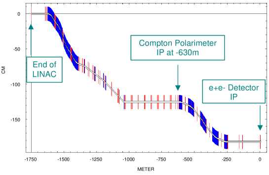
The concept of the polarimeter that we propose for TESLA is based on the well established laser backscattering method, as it was already envisaged in the TESLA CDR [2]. The proposed location of the Compton IP, where the laser beam crosses the electron or positron beam, is 630 meters upstream of the center of the detector, near the end of a long straight section of the beam delivery system (BDS), see Fig. 1. This part of the beamline is foreseen for general beam diagnosis and is also well suited for high quality beam polarization measurements.
Although the polarization vector experiences large rotations (due to the g-2 effect) as the beam traverses the bends of the BDS, the beam and spin directions at the chosen polarimeter site are precisely aligned, except for a parallel offset, with those at the interaction point. A polarization measurement at the proposed upstream location will therefore provide a genuine determination of the quantity of interest, as long as beam-beam effects are negligible or correctable. This is indeed the case. We estimate the beam-beam induced depolarization at TESLA to be 0.5%.
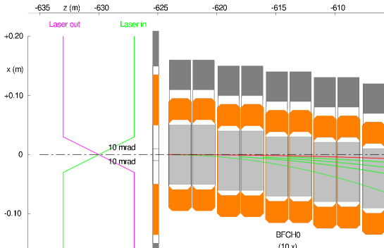
Fig. 2 shows a layout of the Compton Polarimeter. The laser beam crosses the electron or positron beam with a small crossing angle of 10 mrad at z = -630 m, just upstream of a train of ten C-type dipole magnets (BFCH0) which bend the beam horizontally by 0.77 mrad. The Compton scattered electrons are momentum analyzed in the field of the dipoles and detected with a segmented 14 channel gas Cerenkov counter. An optional calorimetric photon detector can also be employed further downstream.
The laser system that we envisage for the polarimeter should be similar to the laser configuration that has been developed by Max Born Institute for the Tesla Test Facility (TTF) photo injector gun at DESY [6]. This laser can be pulsed with a pattern that matches the peculiar pulse and bunch structure of TESLA. In this way it is possible to achieve very high luminosity, typically six orders of magnitude higher than with continuous lasers of comparable average power.
The statistics of Compton produced events is very high to the point where statistical errors will not matter in comparison with systematic errors. We expect a performance similar to the SLD Compton polarimeter at SLAC [7], with an overall precision of for the measurement of the beam polarization.
2 General Considerations
The spin motion of a deflected electron or positron beam in a transverse magnetic field follows from the familiar Thomas-Larmor expression
| (1) |
where and are the orbit and spin deflection angles, is the beam energy, , and is the famous g-factor anomaly of the magnetic moment of the electron.
In order to guarantee that the polarization measurement at the chosen polarimeter site does not suffer from systematic misalignments of the beam direction, we will postulate the following alignment tolerances
where denotes the polar angle. The beam direction at the polarimeter site should therefore be aligned with the collision axis at the interaction point to within .
The strong beam-beam interaction at the collider IP will diffuse the angular spread of the beam. In Table 1 we have listed the rms values of the orbital angular spread of the disrupted beams at TESLA as obtained by O. Napoly. From the orbital rms values we have determined the associated rms spin distribution angles which are listed in Table 1. Based on these numbers, we estimate the overall depolarization of the spent beam to be , independent of beam energy. Assuming that the beam-beam interaction proceeds in a symmetric fashion upstream and downstream from the IP, we estimate the effective depolarization of the beam before the IP to be half of the overall effect, i.e. .
250 GeV 245 27 139 15 400 GeV 153 17 139 15

3 Compton Polarimeter
The Compton kinematics are characterized by the dimensionless variable
| (2) |
where is the initial electron energy, is the initial photon energy, is the crossing angle between the electron beam and the laser, is the electron mass.
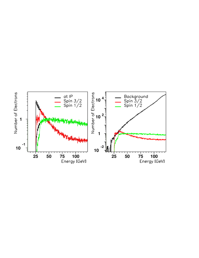
The energy spectra, the associated spin asymmetry and the scattering angles of the Compton scattered electrons and photons are shown in Fig. 3 for a beam energy of 250 GeV and a green laser (2.33 eV). For much higher or lower beam energies, it will be advantageous to change the wavelength of the laser. The multi-photon analyzing power is also indicated in this figure.
The longitudinal polarization of the electron beam is determined from the asymmetry of two measurements of Compton scattering with parallel and antiparallel spin configurations of the interacting electron and laser beams.
For the TESLA Compton polarimeter, we plan to employ electron detection in the multi-event regime as the principle detection method. We will, however, reserve the multi-photon detection method as an option, especially for TESLA operation at the Z-pole. Furthermore, we would like to point out that it can be very useful for calibration purposes to operate occasionally in the single-event regime, either with reduced pulse power of the laser or even with cw lasers.
configuration TESLA-500 250 2.33 0.5 35 1.5 TESLA-800 400 1.165 1.0 71 6.0 Giga-Z 45.6 4.66 0.2 14 0.2
min max Analyzing Stat. Rate # (mm) (mm) low high Power Weight (mbarn) (MHz) 3 -75 -80 0.100 0.107 0.927 0.355 3.35 0.503 4 -70 -75 0.107 0.115 0.812 0.297 3.79 0.568 5 -65 -70 0.115 0.123 0.687 0.232 3.92 0.588 6 -60 -65 0.123 0.134 0.554 0.165 4.14 0.621 7 -55 -60 0.134 0.146 0.415 0.099 4.37 0.655 8 -50 -55 0.146 0.161 0.268 0.044 4.70 0.705 9 -45 -50 0.161 0.178 0.114 0.008 5.10 0.765 10 -40 -45 0.178 0.201 -0.044 0.001 5.57 0.835 11 -35 -40 0.201 0.229 -0.203 0.026 6.28 0.943 12 -30 -35 0.229 0.268 -0.355 0.075 7.25 1.087 13 -25 -30 0.268 0.321 -0.489 0.133 8.74 1.311 14 -20 -25 0.321 0.401 -0.577 0.176 11.28 1.692 all -20 -90 0.089 0.401 68.49 10.273 Statistical Error for 1 second:
For the determination of event rates and statistical errors, we will use the reference parameters listed in Table 2, where () is the laser average(pulse) intensity and is luminosity. In order to be consistent with the cross sections in Fig. 3, we list the wavelengths for a Nd:YAG laser. The wavelengths of the Nd:YLF laser are only slightly different. Not explicitly listed are the crossing angle and the size of the laser focus , which are assumed to be common for all configurations.
The Table 3 lists the binned cross sections and event rates in the electron detector ( and are the scattered electron energy and position) for the first reference configuration of Table 2. As these events are bunched and recorded as analog signals at the bunch crossing frequency, there is no problem with apparently high rates, as we do not actually count individual events.
laser beam energy 250 GeV 2.3 eV charge or energy/bunch bunches/sec 14100 14100 bunch length 1.3 ps 10 ps average current(power) 0.5 W beam crossing angle 10 mrad luminosity cross section detected events/sec detected events/bunch stat. error/sec negligible syst. error
The analyzing power for each bin and the associated statistical weights for a beam polarization P = 0.80 are also given in Table 3. Furthermore, we list the statistical errors of the beam polarization for a measurement duration of 1 second. We conclude from these numbers that genuine statistical errors originating from the Compton event statistics will be exceedingly small and likely negligible in comparison with systematic effects. We expect an overall precision of for the measurement of the beam polarization. As an example, Table 4 gives typical polarimeter parameters for TESLA-500. The performance is similar for other energy regimes of TESLA. More details are given in [12].
We have also considered the possibility of downstream polarimeter locations, which would in principle permit to investigate beam-beam effects experimentally. However, disrupted beam polarimetry appears very difficult because of severe background from energy-degraded beam electrons as shown in Figure 3 for electrons, green laser and nominal beam extraction parameters with reduced collimation at .
References
- [1] R. Alley, H. Aoyagi, J. Clendenin, J. Frisch, C. Garden, E. Hoyt, R. Kirby, L. Klaisner, A. Kulikov, R. Miller, G. Mulhollan, C. Prescott, P. Saez, D. Schultz, H. Tang, J. Turner, The Stanford Linear Accelerator Polarized Electron Source, Nucl. Instr. and Meth. A365 (1995) 1.
- [2] R. Brinkmann et al., Conceptual Design Report of a 500 GeV Linear Collider with integrated X-ray Laser Facility, DESY-1997-048, 1997.
- [3] V.E. Balakin and A.A. Mikhaillichenko, The Conversion System for Obtaining High Polarized Electrons and Positrons, Preprint INP 79-85, 1979.
- [4] K. Flöttmann, Investigation Toward the Development of Polarized and Unpolarized High Intensity Positron Sources for Linear Colliders, DESY-93-161, 1993.
- [5] SLAC-Proposal-E166, October 2002.
- [6] I. Will, P. Nickles and W. Sandner, A Laser System for the TESLA Photo-Injector, internal design study, Max-Born-Institut, Berlin, 1994.
- [7] M. Woods, The Scanning Compton Polarimeter for the SLD Experiment, SLAC-PUB-7319, 1996; 12th Int. Symposium on High-Energy Spin Physics (Spin96), NIKHEF, Amsterdam, Proceeding eds. C.W. de Jager et al., World Scientific, 1997, p. 843.
- [8] I.F. Ginzburg, G.L. Kotkin, V.G. Serbo, and V.I. Telnov, Nucl. Instr. and Meth. 205 (1983) 47.
- [9] W.Y. Tsai, L.L. DeRaad, and K.A. Milton, Phys. Rev. D6 (1972) 1428; K.A. Milton, W.Y. Tsai, and L.L. DeRaad, Phys. Rev. D6 (1972) 1411.
- [10] H. Veltman, Radiative corrections to polarized Compton scattering, Phys. Rev. D40 (1989) 2810; Erratum Phys. Rev. D42 (1990) 1856.
- [11] M. L. Swartz, A Complete Order- Calculation of the Cross Section for Polarized Compton Scattering, Phys. Rev. D58:014010 (1998); hep-ph/9711447; SLAC-PUB-7701, 1997.
- [12] V.Gharibyan, N.Meyners, P.Schuler, The TESLA Compton Polarimeter, DESY LC-DET-2001-047, 2001; http://www.desy.de/~lcnotes/.