Abstract
We give the results of an analysis of some 18 rise-time calibrations which are based on data collected in 1996/97. Such measurements are used to determine the absolute polarization scale of the transverse electron beam polarimeter (TPOL) at HERA. The results of the 1996/97 calibrations are found to be in good agreement with earlier calibrations of the TPOL performed in 1994 with errors of 1.2% and 1.1%. Based on these calibrations and a comparison with measurements from the longitudinal polarimeter (LPOL) at HERA carried out over a two-months period in 2000, we obtain a mean LPOL/TPOL ratio of 1.018. Both polarimeters are found to agree with each other within their overall errors of about 2% each.
1 Introduction
Two polarimeters are employed at the HERA ep storage ring to measure the polarization of its 27.5 GeV electron or positron beam. Both instruments are laser backscattering Compton devices. The TPOL polarimeter measures the transverse beam polarization by detecting the associated angular anisotropy of the backscattered Compton photons. The original configuration of this instrument has been covered in considerable detail [1, 2, 3, 4, 5] and recent upgrades are described in [6]. The LPOL polarimeter measures the longitudinal beam polarization between the spin rotators at the HERMES experiment by detecting an asymmetry in the energy spectra of the Compton photons [7].
In this paper, we will present the results of an analysis of rise-time calibration data which were collected in 1996/97. Such measurements are used to determine the absolute polarization scale of the TPOL polarimeter. These results will be compared with earlier TPOL calibrations obtained in 1994 and with recent cross calibrations with the LPOL polarimeter.
2 The rise-time calibration method
Electrons or positrons are injected unpolarized at 12 GeV into the HERA storage ring and are subsequently ramped to the nominal beam energy of 27.5 GeV. Transverse polarization evolves then naturally through the spin flip driven by synchrotron radiation (the Sokolov-Ternov effect [8]) with an exponential time dependence
| (1) |
For a circular machine with a perfectly flat orbit the spin vector of the positrons (electrons) will be exactly parallel (antiparallel) to the direction of the guide field and the theoretical maximum of the polarization has been calculated to be , with an associated rise-time constant
| (2) |
where is the Lorentz factor, is the radius of curvature of the orbit and the other symbols have the usual meaning.
For rings such as HERA with the spin rotators needed to get longitudinal polarization at experiments and/or reversed horizontal bends, can be reduced substantially below and can be modified too, see Table 1. Synchrotron radiation also causes depolarization which competes with the Sokolov-Ternov effect with the result that the equilibrium polarization is reduced even further. Moreover the depolarization is strongly enhanced by the presence of the small but non-vanishing misalignments of the magnetic elements and the resulting vertical orbit distortions which are typically 1 mm rms.
These effects are treated in the formalism of Derbenev and Kondratenko [9] which has been summarized in [10]. Then the equilibrium polarization and the time constant can be written as
| (3) |
| (4) |
where the unit vector describes the polarization direction which is a function of the machine azimuth and the phase space coordinate , the unit vectors and describe the magnetic field orientation and the direction of motion, and is the circumference of the machine. The angular brackets denote an average over phase space at azimuth . The term with accounts for the radiative depolarization due to photon-induced longitudinal recoils and the term with in the numerator of 3 arises from the dependence of the radiation power on the spin orientation.
These expressions can be summarized in the scaling relation
| (5) |
between the actually observed parameters and of equation 1 and the theoretical values and which are obtained by ignoring terms with in equations 3 and 4. For the HERA machine at 27.5 GeV they take the values in Table 1 [11]:
HERA status year flat 1994 0.915 36.7 non-flat 1996/97 0.891 36.0
The correction in equation 5 results from the term in the numerator of equation 3. In the case of a flat ring, is negligible compared to . However, for a non-flat HERA, namely with spin rotators activated at HERMES, remains small but can still be significant. Since the magnitude of depends on the distortions of the machine, it is very difficult to calculate reliably [11].
The scaling relationship of equation 5 can be exploited to predict the expected equilibrium polarization when we know the remaining quantities , , and . Through comparison of the actually measured value of with the predicted value from equation 5 we can therefore calibrate the polarimeter.
This is the essence of the rise-time method. It requires knowledge of the theoretical maximum values for the machine in the absence of depolarizing spin diffusion effects, i.e. and from equations 3 and 4, and a measurement of the actual rise-time from a fit of data to the functional form of equation 1. For a non-flat ring we also need to know . However, by comparison with rise-time calibrations obtained earlier with a flat machine, we will be able to examine this term experimentally.
3 Experimental Procedure
In order to take rise-time calibration data which are free from major systematic effects it is essential that the build-up of polarization proceeds under conditions of an extremely stable machine performance since even minor operator adjustments in the course of a measurement may change the parameters of the functional form that describes the time dependence. For this reason rise-time calibrations require dedicated HERA operation, where the machine is brought to a very stable condition and is then only monitored without further operator invention. The beam polarization is then destroyed by the resonant depolarization technique by applying an rf field to a weak kicker magnet [12]. When the baseline polarization has been established the depolarizing rf is turned off at time and the subsequent exponential rise is measured under completely quiet machine conditions. After one or two hours, the polarization can be destroyed again for another rise-time measurement and so forth.
In order to retain only data of high quality, we applied the following selection criteria: (a) stable machine and polarimeter conditions; (b) depolarizing rf frequency shifts by no more than 100 Hz (corresponding to a change in beam energy of about 1 MeV); in order to apply this test the beam needs to be depolarized before and after each rise-time measurement; (c) the depolarizer should be activated for about 10 minutes prior to to establish a reliable baseline . Of the rise-time data collected in 1996/97, altogether 18 curves out of a total of 25 survived these cuts. For the older measurements taken in 1994, 8 curves out of 14 could be retained [13].
4 Results and Errors
Figure 1 shows two examples of rise-time data obtained in 1997. The curves are fits to the following functional form, with , and as free fitting parameters
| (6) |

The appropriate input values for and were listed in table 1. The parameter is the calibration factor for the polarization measurement of the polarimeter. The results of the 1996/97 rise-time fits are listed in table 2, together with the older calibration data from 1994 which had been reported earlier [13].
Index Year Run No. No. (sec) (sec) 1 1994 2370 0.936 0.021 2 1994 2442 0.976 0.042 3 1994 2444 0.900 0.038 7 1994 2482 0.960 0.030 8 1994 2484 0.956 0.023 9 1994 2486 0.955 0.028 10 1994 2488 0.994 0.021 11 1994 2492 0.902 0.026 1 1996 5138 0.971 0.042 1255 55 0.644 2 1996 7702 1.089 0.028 1637 42 0.788 3 1996 8382 1.006 0.023 1328 31 0.765 4 1997 2778 0.996 0.042 1392 61 0.680 5 1997 2824 0.962 0.032 1342 47 0.828 6 1997 2896 0.945 0.020 1367 30 0.953 7 1997 3030 0.998 0.031 1396 49 0.763 8 1997 3066 0.963 0.017 1374 25 0.770 9 1997 3278 0.906 0.052 1136 65 0.701 10 1997 3316 0.999 0.043 1251 57 0.597 11 1997 3318 1.030 0.070 1254 90 0.516 14 1997 3669 0.933 0.039 873 37 0.821 15 1997 6654 1.038 0.047 1172 53 0.922 16 1997 6684 1.075 0.035 1362 49 0.784 17 1997 6686 1.062 0.038 1388 53 0.838 18 1997 6688 0.977 0.035 1265 49 0.702 24 1997 9610 1.056 0.026 1391 37 0.795 25 1997 9642 1.040 0.024 1463 36 0.507
In table 3 we give the weighted mean value of , with , the error of the mean value , and the associated . Furthermore we give a rescaled error to account for the underestimation of the original errors indicated by . The scaling is equivalent to adding a common systematic error of size in quadrature, see [14] for an explanation of these procedures.
data set 1994 0.951 0.951 0.009 1.509 0.006 0.011 1996/97 0.999 0.945 0.007 2.744 0.009 0.012
For a proper interpretation of the calibration results shown in table 3, it is important to understand that all TPOL polarization values have been scaled by a factor 0.946 since 1996 [13] in good agreement with the value of 0.951 given here. The subsequent 1996/97 relative re-calibration factor of 0.999 is therefore equivalent to an overall absolute factor of in relation to the original polarization scale used prior to 1996.
The analysis of the 1994 rise-time data reported in [13] assigned an error of 0.032 to the determination of . The error quoted is the rms of the nearly gaussian distribution of K-measurements. This rms value describes the typical error of a single measurement of . The error of the mean value of is then and thus considerably smaller than .
By comparing the calibrations of 1994 and 1996/97, we find excellent agreement within the given errors of 1.1 and 1.2%. Since the 96/97-calibrations were carried out with activated spin rotators at HERMES, in contrast to 1994 when the machine was flat, we can also set an experimental upper limit of about 1.5% on the correction in equation 5 which accounts for the term in the numerator of equation 3.
5 LPOL/TPOL comparison
As the magnitude of the polarization at any particular point in time is an invariant around the HERA ring, a comparison between the TPOL and LPOL polarimeters will provide a cross calibration of the instruments, as long as the spin points fully upright at the TPOL and longitudinal at the LPOL.
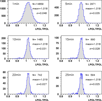
Although it is well known to the operators of the polarimeters and to the members of HERMES that the two instruments appeared to disagree occasionally with each other outside of their quoted errors, it is reassuring to demonstrate a large sample of measurements, covering two months of data taking in April/May of 2000, which exhibits a consistent and stable performance of both polarimeters. We have plotted the LPOL/TPOL ratio for this time period in figure 2 for six different integration times ranging from 1 to 25 minutes. We obtain a consistent mean ratio of 1.018 with an error of the mean of less than 0.001.
Since the statistical fluctuations are vanishing with higher averaging periods, one can estimate the systematic error of the TPOL measurement from the observed rms of the distribution and the quoted LPOL systematic error [7]. Assuming uncorrelated errors for the two polarimeters, we obtain .
6 Acknowledgments
The rise-time calibration analysis presented in this article and the LPOL/TPOL comparison is based on data collected by the HERMES Polarimeter Group. We thank Desmond Barber for discussions on radiative polarization and depolarization mechanisms.
References
- [1] D.P. Barber et al., The HERA polarimeter and the first observation of electron spin polarization at HERA, Nucl. Instr. Meth. A329 (1993) 79.
- [2] D.P. Barber et al., High Spin polarization at the HERA electron storage ring, Nucl. Instr. Meth. A338 (1994) 166.
- [3] D.P. Barber et al., The first achievement of longitudinal spin polarization in a high energy electron storage ring, Phys. Lett. B434 (1995) 436.
- [4] D. Westphal et al., Polarisationsmessungen am HERA Elektronenstrahl, DESY F35D-93-04, diploma thesis, Univ. Hamburg, 1993.
- [5] K.P. Schüler, Polarimetry at HERA, Proc. 12th Int. Symp. on High Energy Spin Physics (SPIN 96) Amsterdam, eds. C.W. de Jaeger et al., World Scientific, 1997, p. 822.
- [6] K. Long, K.P. Schüler, Polarisation measurements on beams, NIM A, article in press.
- [7] M. Beckmann et al., The Longitudinal Polarimeter at HERA, Nucl. Instr. Meth. A479 (2002) 334.
-
[8]
A.A. Sokolov, I.M. Ternov,
Sov. Phys. Doklady 8 (1964) 1203;
I.M. Ternov, Yu.M. Loskutov, L.I. Korovina, Sov. Phys. JETP 14 (1962) 921. -
[9]
Ya.S. Derbenev, A.M. Kondratenko, Sov. Phys. JETP 37 (1973) 968;
S.R. Mane, Phys. Rev. A36 (1987) 105. - [10] D.P. Barber, G. Ripken, Radiative Polarization, Computer Algorithms and Spin Matching in Electron Storage Rings, Handbook of Accelerator Physics and Engineering, eds. A.W. Chao and M. Tigner, 2nd edition, World Scientific, 2002.
- [11] D.P. Barber, private communications
- [12] F. Zetsche, Use of Resonant Depolarization at the HERA Electron Ring, Proc. 12th Int. Symp. on High Energy Spin Physics (SPIN 96) Amsterdam, eds. C.W. de Jaeger et al., World Scientific, 1997, p. 846.
- [13] S. Barrow et al., Interim Report on the Measurement of the Positron Beam Polarization, HERMES Polarimeter Note, Jan. 1996.
- [14] Particle Data Group, Review of Particle Physics, Chapter 4.2 Averages and fits, Eur. Phys. J. C3 (1998) p. 10.