Chapter 1 The Trigger System of the ARGO-YBJ detector
Abstract
The ARGO-YBJ experiment has been designed to detect air shower events over a large size scale and with an energy threshold of a few hundreds GeV. The building blocks of the ARGO-YBJ detector are single-gap Resistive Plate Counters (RPCs). The trigger logic selects the events on the basis of their hit multiplicity. Inclusive triggers as well as dedicated triggers for specific physics channels or calibration purposes have been developed. This paper describes the architecture and the main features of the trigger system.
1. Introduction
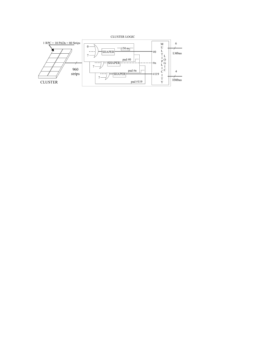
The ARGO-YBJ experiment [1] is devoted to a wide range of fundamental issues in cosmic rays and astroparticle physics, including in particular -ray astronomy and -ray bursts physics at energies 100 GeV. The detector consists of an array of single layer RPCs that covers , surrounded by a partially instrumented guard ring. It is organized in modules of 12 chambers called CLUSTER. Each chamber is made of 80 strips and the entire detector comprises 130 CLUSTERs in the central carpet. The 960 strips in each CLUSTER are processed by the CLUSTER logic (fig. 1). For time measurement and trigger purposes, adjacent strips are logically OR-ed together in groups of 8 defining a logic unit called PAD of (15600 in total). The PAD signals are stretched to 150 ns to guarantee that the particles of the same shower are in coincidence. The CLUSTER logic outputs a 6-bit Low Multiplicity weighted bus (when , , , , , PADs are fired) and a 4-bit High Multiplicity weighted bus (when , , , PADs are fired). The CLUSTER logic is housed in a location nearby the CLUSTER, called Local Station (LS).
The PADs provide a detailed space-time picture of the shower front and they are the basic inputs to the trigger logic, which validates an event on the basis of specific fired PADs density criteria.
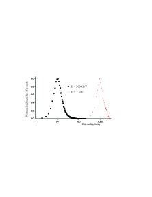
The ARGO-YBJ experiment has been designed to study a wide range of fundamental issues in cosmic ray physics and -ray astronomy. The energy experimental range is very large, bridging the GeV and TeV energy regions of the showers, and moreover the particle density distribution changes with the distance from the shower axis. Showers with very low energy, in the range of a few hundreds GeV, are expected to fire less than 100 PADs spread on the entire carpet (fig. 2). At very high energy, in the range of tenths of TeV and beyond, the showers present a specific spatial distribution, characterized by a core structure. The trigger logic should be able to select events exceeding a programmable threshold of PADs, fired by the same shower. At low threshold, such algorithm allows us to trigger showers with arbitrary hit density. Raising the thresholds, showers at higher energy can be triggered. A local density trigger can be obtained by applying the same logic to each detector partition made of four adjacent clusters (SUPERCLUSTER). This local density concept can be extended to an arbitrary CLUSTER pattern, requiring that a programmable number of clusters exceeds a specific threshold setting to produce a trigger. These three algorithms cover the intended physics range of interest for the ARGO-YBJ experiment, featuring a trigger scheme based on both event density and hit multiplicity.
2. The Trigger Architecture
The three different trigger logics are based on the Low Multiplicity (LM) and High Multiplicity (HM) busses driven by the LSs. In order to preserve the original data timing, all the hardware is implemented as synchronous pipelines with a common system clock at 33 MHz, generated and distributed by a specific low-jitter balanced clock tree.
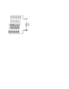
The first trigger logic generates a signal when a programmed threshold of fired PADs is reached or exceeded on the entire detector (LM Trigger). The LM Trigger uses the LMbus from each LS and processes from the central carpet a total of bit inputs. In order to handle a data word that wide, the logic adopts a three-level concentration scheme. The Level-1 is based on the LOWM boards. This module synchronizes the LMbusses from 12 LSs to the system clock, stretches the bit width to 8 clock cycles ( 243 ns) in order to garantee the coincidence across the 12 CLUSTERs in the worst case hit timing and outputs on a 7-bit binary encoded bus the total multiplicity, updated every clock cycle. The central carpet is split in two regions as shown in Fig. 3. Each region comprises 65 CLUSTERs processed by 6 LOWM boards. In the same fashion, two Level-2 boards called LOW stretch the Level-1 7-bit outputs to 12 clock cycles ( 360 ns) and output on a 10-bit binary encoded bus the total multiplicity for each half carpet. At the end, a single Level-3 board TLOW shapes the Level-2 10-bits outputs to about 400 ns and encodes the total 11-bit multiplicity for the entire carpet. This board generates the low multiplicity trigger when the hit total number exceedes the programmed threshold on the carpet. Each LOWM splits a 12 CLUSTER region in 3 SUPERCLUSTERs. A specific threshold can be assigned to each SUPERCLUSTER and the module generates a Fast Trigger if at least a SUPERCLUSTER hit number exceedes its correspondent threshold.
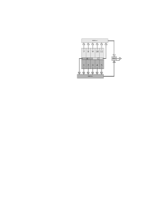
The third trigger logic produces an output when a programmable threshold of CLUSTERs with a specific multiplicity in the range coded by the HMbus is excedeed (HM Trigger). For instance, this logic allow us to trigger on events where at least N CLUSTERs present a hit multiplicity . The HM Trigger is split in four sections, each handling in parallel a specific bit from each LS’s 4-bit HMbus: the HM 7, 16, 32, 64 Triggers. Each section processes from the central carpet a 130-bit input and it is implemented in two levels as shown in fig. 4. Each HIGHM board synchronizes the i-th bits of the HMbusses from 65 LSs to the system clock. Also, it stretches the bit width to 12 clock cycle ( 360 ns) in order to count the CLUSTERs in coincidence across half carpet with the pertaining hit multiplicity. The two 7-bit binary encoded busses driven by the HIGHM boards are merged into the THIGH board that calculates the total number of CLUSTERs across the entire carpet. The LM Trigger, the Fast Trigger and the four HM Triggers are handled by a TRBOX board which can mask a specific trigger source and OR them together. If the Data Acquisition System does not assert a Veto signal, the trigger proposal becomes a trigger signal. Apart from the system initialization, the trigger system activity is fully self governing.
3. The trigger system boards
All the trigger boards are VME double height slaves with A32/D08(O), D16, D32, and D32:BLT data transfer capabilities. Differential data in P(ositive) ECL standard assures a superior performance in terms of sustainable data rates and a cable driving capability using cheap twisted-pair media. Through the VME bus the main trigger features and operating modes can be programmed and monitored.
4. Conclusion
In the realization of these modules we started from the beginning using VHDL and synthesis tools. The use of the FPGAs give to us enough flexibility giving an easy way to upgrade existing boards with new features when necessary.
5. References
1. Surdo A. et al. 2003, in this proceedings.