A RICH Multiplicity Veto
for the HERA-B Experiment
2Institut für Physik, Universität Dortmund, D–44221 Dortmund, Germany,
now at: Aareal Bank AG, Wiesbaden, Germany
3Institut für Physik, Universität Dortmund, D–44221 Dortmund, Germany,
now at: Bundesamt für Wehrtechnik und Beschaffung, Koblenz, Germany )
Abstract
We present the design and commissioning of a new multiplicity veto for the HERA B detector, a fixed-target spectrometer originally designed to study the physics of mesons in proton-nucleus interactions. The HERA B trigger is a message-driven multi-level track trigger. The first level trigger (FLT) consists of custom-made electronics, and the higher trigger levels are implemented as PC farms.
The multiplicity veto has been designed to reject high-multiplicity events before they enter the trigger chain. A veto signal is generated based on the comparison of the number of photons in part of the HERA B ring-imaging Čerenkov counter (RICH) with a programmable threshold.
The RICH Multiplicity Veto is a modular system. First the hits in 256 detector channels are summed by Base Sum Cards (BSC), then FED Sum Cards (FSC) sum the subtotals of up to eight BSCs. Finally the Veto Board (VB) takes the veto decision based on the sum of up to 14 FSCs.
The RICH Multiplicity Veto has been successfully installed and commissioned in HERA B. The measured veto efficiency is , and the system is used in the routine data-taking of the HERA B experiment.
Poster presented at the IEEE Nuclear Science Symposium 2002,
Norfolk, Virginia, November 12–14, 2002
This work was supported by the German Bundesministerium für
Bildung und Forschung (BMBF) under the contract number 5HB1PEA/7.
1 Introduction
1.1 The HERA B Experiment
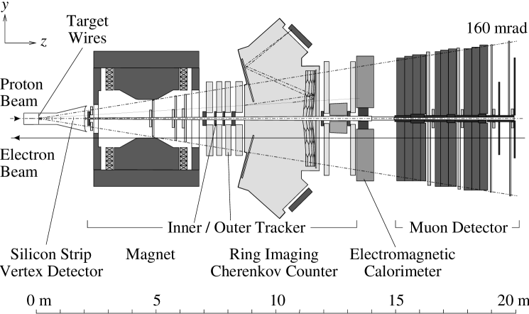
The HERA B experiment at the electron-proton collider HERA at DESY in Hamburg, Germany, is a fixed-target spectrometer with large angular acceptance. HERA B has been designed to study neutral mesons produced in proton-nucleus interactions. HERA B’s current physics program aims at the measurement of the production of and bound states in different target materials. The HERA B target consists of eight wires in the halo of the HERA proton beam. The wires can be independently moved transverse to the beam to adjust the average number of proton-nucleus interactions per bunch crossing.
The HERA B detector is shown in Fig. 1. It consists of tracking devices and devices used for particle identification. The tracking devices comprise a vertex detector of double-sided silicon micro-strip detectors, and an inner and outer tracking system using micro-strip gaseous chambers with gas electron multiplier foils (GEM-MSGCs) in the inner acceptance region ( from the proton beam direction) and honey-comb drift chambers in the outer acceptance region (). Particle identification is performed in the electromagnetic calorimeter (ECAL), the ring-imaging Čerenkov counter (RICH) [5] and the muon detector built of multi-wire proportional chambers.
To achieve the large suppression of background events needed for and production measurements, a highly selective multi-level trigger system is used. The first level trigger (FLT), built from custom-made electronics, performs a track search in the tracking detectors behind the spectrometer magnet. It has to sustain interaction rates of up to . Track candidates for the FLT are provided by pretriggers in the muon detector and the ECAL, based on hit coincidences in adjacent detector layers and hit clusters in the ECAL. The HERA B detector and trigger are described in greater detail in [3] and references therein.
1.2 Motivation for a RICH Multiplicity Veto
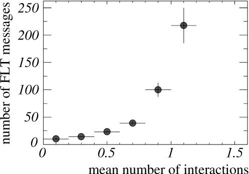
Large hit multiplicities are mainly caused by a superposition of multiple interactions in a single bunch crossing of the HERA proton beam. The number of simultaneous interactions follows a Poisson distribution.
The FLT is based on a track search algorithm implemented in custom-made hardware which requires hits in four superlayers of the HERA B tracking system. Large hit multiplicities lead to an increase of the number of possible hit combinations to form a track in the FLT. As a result, the FLT is sensitive to events with large hit multiplicities, see Fig. 2. Since the FLT is a modular message-driven system, the message load in its network increases with the hit multiplicity which may introduce dead-time in the system. Therefore a mechanism to protect the FLT from processing multi-interaction events is needed. At the same time, this mechanism should preserve a large efficiency for interesting physics signals, e.g. the decay .
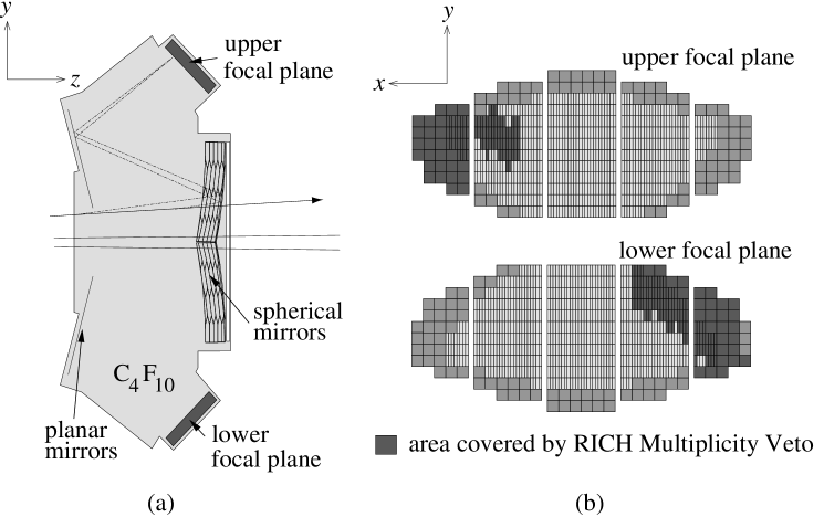
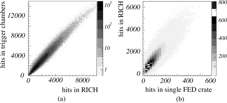
A suitable measure of the hit multiplicity in the HERA B detector is the number of photons generated by charged particles in the RICH. A sketch of the HERA B RICH detector can be found in Fig. 3 (a). As shown in Fig. 4 (a), the number of RICH photons is highly correlated with the number of hits in the tracking chambers used in the FLT. Even in the case when only a small part of the RICH detector is covered, the number of RICH photons in this part is highly correlated with the number of hits in the whole RICH, see Fig. 4 (b). Hence the veto functionality can already be established with partial coverage of the RICH.
The RICH detector is suited to host a multiplicity veto not only from the physics but also from the technological point of view. It has proven to be a very reliable, low-noise system. In addition, its interface to the HERA B data acquisition system (DAQ), the front-end driver (FED), is easily accessible to install the necessary additional electronics.
1.3 Veto Strategy
The strategy of a multiplicity veto using the RICH detector is to provide a fast sum of the number of photons in part of the RICH and to generate a veto signal based on the comparison of this number of photons with an adjustable threshold. In order to stop the trigger chain even before the message-driven processing in the FLT, the veto signal has to be distributed to the pretriggers.
1.4 Design Concepts
The photon signals detected by the photomultipliers of the RICH detector are provided as digitized data at the FEDs. Therefore the summation of hits is performed by digital electronics. The logic of the veto system is implemented in large Complex Programmable Logic Devices (CPLD) [2] to allow for rapid development of the logic and to keep the design flexible. The CPLDs used in the design are well-suited for cascaded summation.
Since the RICH FEDs are distributed in 14 FED crates close to the HERA B detector, the veto system has to be a distributed modular system. The current implementation of the RICH Multiplicity Veto covers two FED crates, see Fig. 3 (b).
The maximum allowed latency of the system is given by the conditional requirement that the pretrigger systems have to be stopped before transfering data to the FLT. Latency measurements show that the maximum allowed latency is given by the muon pretrigger. The veto signal has to arrive at the muon pretrigger within after the interaction at the HERA B target.
The RICH Multiplicity Veto is a new hardware component to be integrated into an existing detector. Therefore care is taken not to introduce additional electronic noise into the detector front-end. The electronics boards that receive the data from the FEDs are plugged directly on the FED boards in order to keep signal paths short. In addition, the signal lines on all electronics boards are routed carefully.
The data inside the multiplicity veto has to be transmitted over approximately from the detector front-end to the electronics trailer which is situated outside the experimental area. Differential PECL logic is used for all flat cable connections to improve the noise immunity.
Various specialized test boards and internal test facilities are needed to allow for fast and controlled commissioning of the veto system.
2 The Electronics Boards
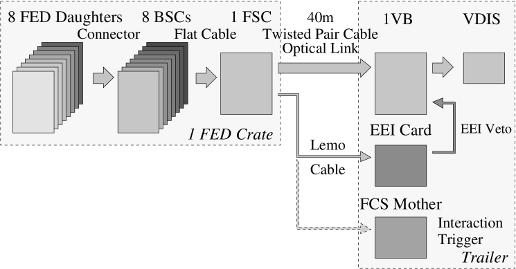
An overview of the RICH Multiplicity Veto system is shown in Fig. 5. The RICH FED is distributed over 14 FED crates with up to eight FED daughter cards processing data from 256 photomultiplier channels each. The data of eight FED daughter cards are transmitted to eight Base Sum Cards (BSC), where they are summed. The sums of the eight BSCs are transmitted to the FED Sum Card (FSC), which calculates the subtotal of the hits in a single RICH FED crate. This sum is transmitted via twisted-pair flat cables or an optical link to the Veto Board (VB), which is situated in the HERA B electronics trailer. A modified I2C bus system is used for communication among the modules of the RICH Multiplicity Veto system.
The veto decision calculated from the sum of up to 14 FSC subtotals is distributed to the pretrigger via the Veto Distributor (VDIS) [9]. A veto signal from the ECAL Energy Inhibit (EEI) board can be combined with the signal from the RICH Multiplicity Veto system. The EEI is a veto system complementary to the RICH Multiplicity Veto. It is based on the analog energy sum in the inner part of the ECAL.
In addition, the veto signal generated from a single FSC can be fed into the Fast Control System (FCS) mother card, which distributes triggers in the HERA B experiment. In this “Fast Veto” mode, the veto system can be used as a low-bias interaction trigger.
For the data-taking period 2002/2003, 15 BSCs, 2 FSCs, and the VB have been installed in the HERA B detector.
2.1 The Modified I2C Bus
A bus system for the RICH Multiplicity Veto has to address up to boards and to transmit signals over distances of more than . The Fast Control System [8], the central bus system of the HERA B experiment, cannot be extended to fulfill these requirements.
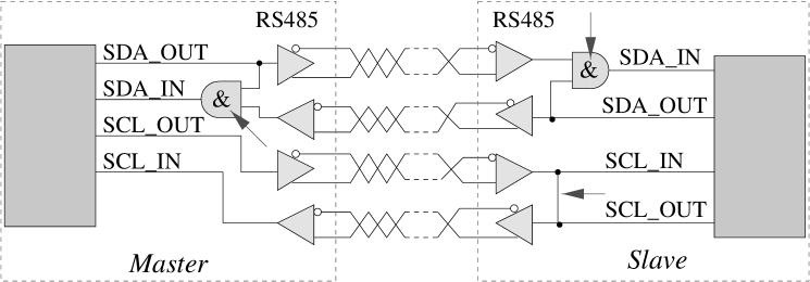
The I2C bus standard provides an easy and widely used protocol to implement the internal communication of the RICH Multiplicity Veto system. The original protocol is based on two bi-directional lines, one for data transmission and one for the transmission of clock signals. However, to use the I2C bus in the RICH Multiplicity Veto system, some modifications have been made to the protocol. The I2C bus controller used in the RICH Multiplicity Veto [1] is operated in a special long-distance mode with four uni-directional lines. This mode allows to use long-distance drivers (RS485) for the I2C lines. In order to ensure the correct position of the acknowledge signal after data transmission in the long-distance mode, a feedback loop has to be introduced to the data and clock lines, as shown in Fig. 6.
The I2C master controller is situated on the VB. It is controlled via VME commands, while the controllers on the BSCs and the FSCs are operated as I2C slaves. Finite state machines implemented in dedicated CPLDs on these boards are used to operate the I2C slave controllers.
The BSCs and the FSCs are entirely controlled via the I2C bus. The bus system is used to access the command, status, and reference registers of the CPLDs on the BSCs and FSCs boards in order to initialize and monitor these boards.
2.2 The Base Sum Card
The BSC is a six-layer electronics board which is plugged directly on an FED daughter card. Almost the complete logic of the board is implemented in two CPLDs. Each of the CPLDs processes signals from 128 of the 256 detector channels provided by the FED daughter card.
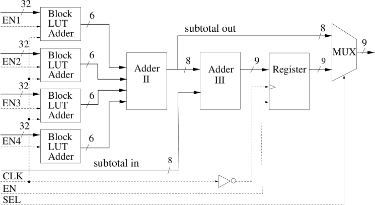
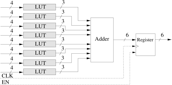
The summation logic of the CPLD is shown in Fig. 7. The 128 channels are further divided into four 32-bit blocks. For every 32-bit block, a “block-LUT adder” unit is implemented, see Fig. 8. Eight look-up tables are used to count the number of hits in four bits and transform them into a three-bit number. Each 32-bit block can be masked individually to account for problematic channels in the detector readout.
The subtotals of the four 32-bit blocks are summed by an additional adder unit, and the subtotal of the second CPLD is added, before the sum is transmitted to the FSC.
In order to assign the veto signal generated by the RICH Multiplicity Veto to a given event, the bunch crossing number (BX) of the current event is transmitted to the FSC together with the subtotal of the BSC. The BX is provided by the HERA B FCS system and transmitted to the BSC via the backplane of the FED crate.
While for the internal logic of the BSC TTL is used, the logic level is transformed to differential PECL for data transmission. Due to a limitation of number of lines on the flat cable, the least significant bit (LSB) of the sum is discarded before the data transmission occurs.
2.3 The FED Sum Card
The FSC, situated in an FED crate together with up to eight BSCs, receives data from the BSCs via flat cables. The summation logic is depicted in Fig. 9. The subtotals of the BSCs are added. To check the synchronization of the BSCs, the BXs which are transmitted together with the subtotals are compared. In case of inconsistencies, an error code is generated. The result of the summation and the error code are transmitted to the VB.
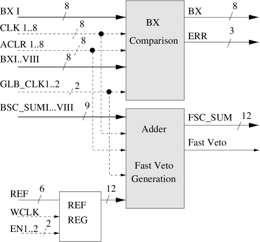
The subtotal of the FSC is compared with an adjustable threshold, and a “Fast Veto” signal is generated if the subtotal is equal to or larger than the threshold. The Fast Veto signal can be fed into the FCS mother card via a Lemo cable to be used as an interaction trigger, sensitive to minimal activity in part of the RICH detector.
Since the data transmission from the FSC to the VB takes place in a harsh hadronic environment, the FSC foresees data transmission via optical links in addition to conventional twisted-pair flat cables. In-situ tests show that using flat cables for the data transmission in the HERA B experimental area is feasible. Moreover, in flat cable data transmission, no additional time is needed to serialize the data for the optical transmission, thus the latency of the system is smaller compared to optical transmission. Therefore, transmission via flat cables has been chosen for the installation of the RICH Multiplicity Veto system.
2.4 The Veto Board
The VB is a 6U electronics board designed in VME standard. It is situated in the HERA B electronics trailer. The subtotals of up to 14 FSCs arrive at the input connectors of the VB via flat cables. The VB is designed to consist of a main board and a mezzanine board, each processing the data from seven FSCs. In the current installation in HERA B, only the main board is used.
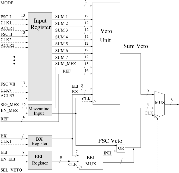
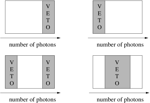
The veto logic of the VB is shown in Fig. 10. The sums of seven FSCs and the final sum of the mezzanine board are written to input registers before they are transmitted to the veto unit. The veto unit calculates the final sum, and the veto signal is generated based on a comparison with two adjustable thresholds. Hence, four different veto modi can be chosen, as depicted in Fig. 11. The veto signal from the EEI can combined with the internal veto signal by a logical OR.
The veto can also be generated from a different source: the logical OR of the Fast Veto signals for the FSCs, also combined with the EEI veto, can be used instead of the final sum.
The VME interface of the VB is used to control the entire RICH Multiplicity Veto system, including the I2C bus master controller and all registers of the CPLDs of the VB and – via the I2C bus – of the CPLDs of the BSCs and the FSCs.
The VB monitors the error codes generated by the FSCs due to BX synchronization errors of the BSCs. In addition, the BX synchronization of the FSCs themselves and the number of vetos generated in the last 256 BX, both on the VB and on the EEI, are monitored. This information is available in the status registers of a specialized monitoring CPLD which can be read out via VME.
To transmit the veto decision and the veto rate to the HERA B data stream, the VB provides an interface to the Second Level Buffer (SLB), HERA B’s event buffer made of a network of specialized digital signal processors. On the VB, a modified FED buffer is implemented. It contains the veto decision and the current veto mode, tagged with the FLT BX number, which is provided by the HERA B FCS via the FCS backplane. If the FCS issues a trigger, the content of the FED buffer is transmitted to the SLB and saved in the data stream. Due to this feature, the efficiency of the RICH Multiplicity Veto system can be determined easily, cf. Section 3.2.
Since the internal monitoring provides the number of vetos only for the last 256 BX, i.e. on a statistical basis, a better monitoring mechanism is needed to control the number of events rejected by the RICH Multiplicity Veto system. Thus the veto signal is transmitted to a VME scaler which counts the number of vetos in an adjustable time interval. The scaler is read out via VME, and the measured veto rate is written to the data stream.
3 Commissioning
The commissioning of the RICH Multiplicity Veto system comprises detailed tests of the hardware functionality in the laboratory and measurements of the latency of part of the system and the whole system. Furthermore, the efficiency of the system is determined, and the influence on the HERA B trigger chain and DAQ and on physics signals is studied.
3.1 Laboratory Tests
3.1.1 Bit Error Measurements
The laboratory tests are based on a complex test setup using specialized test boards to generate the input and analyze the output of the individual boards so that the bit error level can be determined.
The BSC is tested with a specialized board that emulates the timing and data of the HERA B FED and the FCS, the Pretrigger FED Simulator (PFEDS). This board allows to generate defined test input for the BSC. The test input is designed such that every channel is tested individually, i.e. without bits being set in neighboring channels, hence hardware defects can be located on the BSC. The output of the BSC is written to a FIFO on the Base Sum Test Card (BSTC) where it can be read out via VME and compared with the input.
In the next step, the veto chain is extended by the FSC. With a special adapter, the BSTC can also be used to test the output of the FSC. As for the BSC, every input channel is tested individually. By adding more BSCs, the BX comparison and the summation on the FSC are tested. The Fast Veto signal is tested by programming a threshold on the FSC via the I2C bus and monitoring if the signal is generated correctly and assigned to the correct BX.
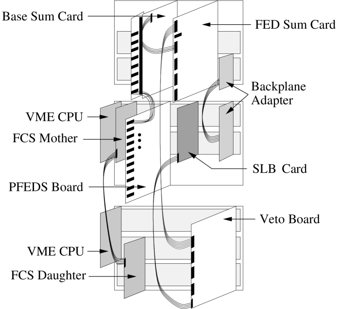
For tests of the VB, the Veto Board Test Card (VBTC) has been designed. The VBTC uses PFEDS data as an input and emulates the output of two FSCs, including the FSC subtotals, the Fast Veto signals, the BXs and the FSC error codes. The timing of these signals can be shifted to emulate errors in the chain of the veto system. An EEI emulator generates signals to test the insertion of the EEI veto in the veto decision of the VB. For all four veto modi, a test of the correct generation of veto signals has been performed. The data transmission to the SLBs is tested with an SLB module, and the signal that triggers the data transmission to the SLB is generated by the HERA B FCS system. In Fig. 12, a test setup for the entire chain of the RICH multiplicity veto system is shown.
The results of the laboratory tests are summarized in Table 1. During the tests, no bit errors could be detected, therefore the error limits quoted in the table are given only by the test statistics.
| Test Procedure | Bit Error Rate |
|---|---|
| BSC: summation | |
| FSC: summation | |
| FSC: BX comparison | |
| FSC: Fast Veto | |
| Veto Board |
3.1.2 Latency Measurements
The system latency has been measured for each board individually. The single board latency is defined as the time interval between the rising edge of the input signal of the board and the rising edge of the output signal.
The latency of the whole RICH Multiplicity Veto chain includes the time of flight from the target to the RICH detector, the latency of the FED system and additional latency introduced by the cable lengths.
The result of the latency measurement is summarized in Table 2. The total latency
is well below the maximum allowed value of .
| Board | Latency [ns] |
|---|---|
| Base Sum Card | |
| FED Sum Card | |
| Veto Board | |
| (Time of Flight, etc.) | |
| Total |
3.2 Efficiency Measurement
The interface of the VB to the HERA B data stream allows for an efficiency measurement of the RICH Multiplicity Veto system [6]. The system can be operated in “spy mode”, i.e. the veto signal is not used to stop the pretriggers but the veto decision is saved in the data stream.
The efficiency of the RICH Multiplicity Veto system is determined by comparing the veto decision made by the hardware with a simulation of the RICH Multiplicity Veto logic based on the recorded data. In the simulation, hits are counted from the recorded data in the area of the RICH detector covered by the RICH Multiplicity Veto system. After discarding the LSB of the subtotal for every installed BSC the total hit sum is compared with the upper and lower veto thresholds used in the data-taking. This simulated veto decision is compared to the actual decision of the RICH Multiplicity Veto hardware. The efficiency is defined as the fraction of correct veto decisions.
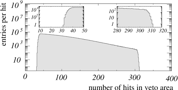
The efficiency measurement is based on a sample of 7.5 million events taken with a minimum bias trigger. Different veto thresholds and veto modi have been used during the data-taking. As an example, in Fig. 13, the hit distribution in the area covered by the RICH Multiplicity Veto system is shown for accepted events of a run in which the veto accepted events inside a window of 30–300 hits.
The measurement shows that in very rare cases a wrong veto decision is taken, but only if the number of hits is close to the threshold. The efficiency averaged over all thresholds and modi is
3.3 Influence on Trigger and DAQ
To test the influence of using the RICH Multiplicity Veto in the data-taking, data is taken with the system actively rejecting events. Some important parameters that determine the trigger and DAQ timing are measured as functions of the upper veto threshold. As an example, the FLT input and output rates are shown in Fig. 14.
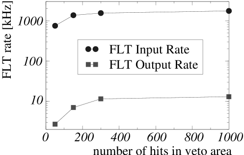
The overall result is that all measured timing parameters are improved. This includes smaller FLT input and output rates, a smaller dead-time of the FCS, smaller event size and reconstruction time and hence a larger physics data rate to tape, cf. Table 3. These measurements show that using the RICH Multiplicity Veto protects the trigger chain and the DAQ from high-multiplicity events. Note however that the improvement values given in Table 3 are only valid for a fixed set of trigger and DAQ settings, which are subject to permanent optimization.
| Value | Improvement |
|---|---|
| FLT input rate | 11% |
| FLT output rate | 12% |
| FCS dead-time | 50% |
| Event size | 10% |
| Reconstruction time | 35% |
| Data rate to tape | 25% |
3.4 Influence on Physics
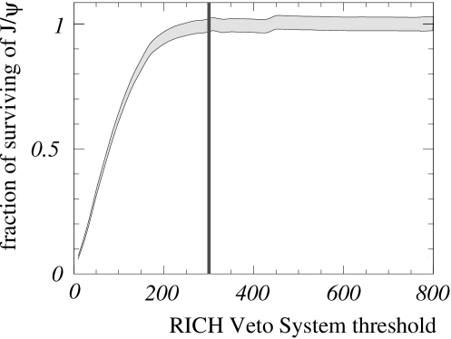
Using data taken during the HERA B commissioning phase from August to October 2002, the influence of the RICH Multiplicity Veto on physics signals in the HERA B detector is studied. The data sample includes approximately 3,500 candidates for the decay . The RICH Multiplicity Veto system has been inactive during the data-taking, and cuts on the veto threshold are applied in the offline analysis. At a “generic” upper threshold of 300 hits in the area covered by the RICH Multiplicity Veto system – corresponding to approximately 2,500 hits in the entire RICH – the survival of mesons and a possible bias on the kinematics are studied.
Fitting the di-muon invariant mass spectrum for events with less than a given number of hits and for all events, the survival fraction of mesons is determined as a function of the RICH veto threshold, see Fig. 15. For an upper threshold of 300 hits, the survival fraction is in the range of 97–100%.
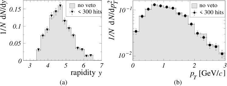
The kinematics can be described by two independent parameters. In this analysis, the rapidity and the transverse momentum are chosen. The di-muon invariant mass spectrum is fitted in bins of and , and the result using only events with less than 300 hits is compared with the result using all events. The distributions are not corrected for detector acceptance and efficiency. Fig. 16 shows the resulting rapidity and transverse momentum distributions. Within errors, no significant bias on the kinematics is observed.
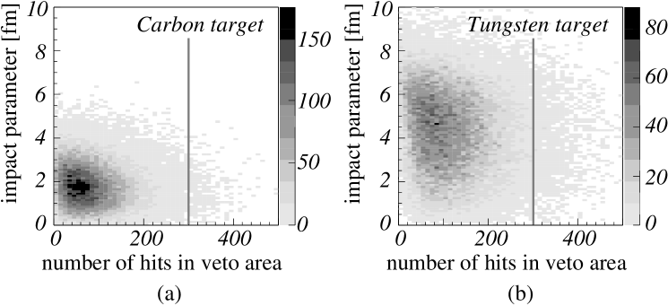
The influence of the RICH Multiplicity Veto on the centrality of the proton-nucleus collision in accepted events is studied using a Monte Carlo simulation of 50,000 events each for Carbon and Tungsten targets. The simulation includes the process mixed with Poisson-distributed inelastic background with a mean value of one interaction. In Fig. 17, the number of expected hits in the area of the RICH covered by the RICH Multiplicity Veto is shown as a function of the impact parameter of the proton-nucleus collision. Only a small fraction of the events is rejected (Carbon: %, Tungsten: %), and the simulation shows no significant centrality bias.
4 Conclusions
Within only 1.5 years, a programmable modular veto system for the HERA B RICH has been designed, built and successfully commissioned. The system provides a fast sum of the number of photons seen in the RICH which is used to reject events with large multiplicities. The system shows very low bit error rates and an efficiency close to 100%. While the trigger and DAQ timing is improved using the RICH Multiplicity Veto system, more than 97% of the events survive the veto decision, and no significant bias on the kinematics is observed.
The RICH Multiplicity Veto system is used routinely in the data-taking of the HERA B experiment.
References
- [1] PCF8584 I2C bus controller data sheet, October 1997.
- [2] FLEX 10k embedded programmable logic device family data sheet ver. 4.1, March 2001.
- [3] I. Abt et al., Measurement of the production cross section in 920-GeV fixed-target proton nucleus collisions, Eur. Phys. J. C26 (2003), 345–355.
- [4] M. Adams, Entwicklung eines Simulationsprogrammes für das Myon-Pretrigger System des HERA B Experimentes und Untersuchungen zum Systemverhalten, Ph.D. thesis, Universität Dortmund, 2001.
- [5] I. Ariño et al., The HERA B Ring Imaging Čerenkov counter, Nucl. Instrum. Meth. A (2003), to be published.
- [6] M. Brüggemann, Untersuchungen zum RICH-Vetosystem des HERA B Experiments, Diploma thesis, Universität Dortmund, 2002.
- [7] C. Cruse, Das RICH-Multiplizitätsveto-System für das HERA B Experiment, Ph.D. thesis, Universität Dortmund, 2002.
- [8] T. Fuljahn, Aufbau und Charakterisierung des schnellen Kontrollsystems für den Detektor HERA B, Ph.D. thesis, Universität Hamburg, 1999.
- [9] H. Riege and R. van Staa, HERA B pretrigger system – VETO distribution box, 1998.