Design and test results of the AMS RICH detector
Abstract
The AMS-02 detector will operate for at least 3 years on the
International Space Station, measuring cosmic ray spectra at about
400 km above sea level over a wide range of geomagnetic latitude.
The proximity focusing ring imaging Čerenkov counter of AMS-02
will measure the particle velocity with
uncertainty, making possible to discriminate Beryllium isotopes up to
about 15 GeV/nucl. In addition its charge measurement will allow to
study the elemental composition of cosmic rays up to Iron. A
prototype of the RICH detector was tested with cosmic rays and on a
ion beam accelerated by SPS, at CERN (October 2002).
[Talk given at the “8th Topical Seminar on Innovative Particle
and Radiation Detectors”, Siena (Italy), 21–24 October 2002.]
1 INTRODUCTION
The Alpha Magnetic Spectrometer (AMS) [1] is a particle detector that will be installed on the International Space Station (ISS) to measure cosmic ray fluxes for at least three years. The AMS goals are the search for cosmic antimatter, the search for dark matter signatures, and the measurement of primary Cosmic Ray (CR) spectra below 1 TeV.
In 1998 a first version of the detector (called AMS-01) has flown aboard of the space shuttle Discovery during the NASA STS-91 mission, and it operated successfully for ten days collecting about hundred million events (refer to [2] for a review of the AMS-01 results). For the ISS 3-year mission, a new version of the detector (called AMS-02, figure 1) is being developed.
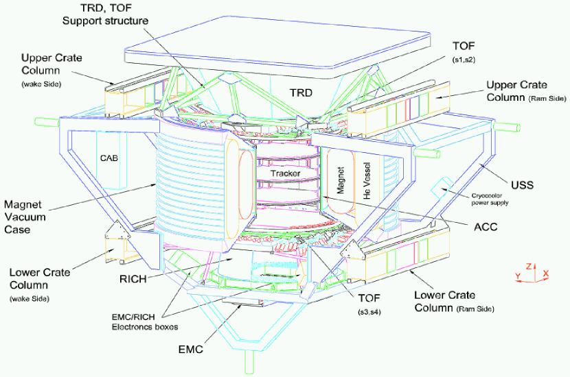
The new apparatus will consist of a transition radiation detector (TRD) followed by two of the four scintillator planes of the time of flight (TOF) system, placed above the superconducting magnet enclosing a Silicon tracker surrounded by an anticoincidence (ACC) system. Below the magnet, the other two planes of the TOF are followed by the proximity focusing ring imaging Čerenkov counter (RICH) and by the electromagnetic calorimeter (EMC).
The large acceptance of the apparatus (about 0.4 sr) and the long duration of the mission (at least 3 years) will allow for a detailed study of the spectra of Hydrogen and Helium isotopes, that can be used to study solar modulation on a weekly basis and to check different CR propagation models. In addition to very precise measurements of the electrons and positrons spectra, AMS will also collect an unprecedented amount of ions events, that are of paramount importance for the fine tuning of the parameters of any propagation model [3]. Finally, the detector will be able to measure high energy gamma rays up to few hundred GeV [4].
2 THE DESIGN OF THE AMS-02 RICH
In order to measure the particle velocity with high accuracy, a Čerenkov detector is highly desirable. Howewer, the need for a wide geometrical acceptance makes impossible the use of an ordinary ring imaging detector: a proximity focusing technique has to be adopted. Hence the RICH subdetector of AMS-02 consists of a flat radiator plane, where the Čerenkov photons are emitted, followed by a gap where these photons propagate in vacuo until they reach the pixel plane, parallel to the radiator (figure 2). The hole in the middle of the pixel plane is exactly above the electromagnetic calorimeter, in order not to have a big amount of matter in front of it.
The basics constituents of the AMS-02 RICH are the radiator plane, the conical mirror, and the pixel plane with 680 16-channel phototubes (PMT) and segmented plastic light guides (LG) to decrease the dead area of the pixel plane.
2.1 The radiator plane
Particle mass identification depends on the momentum and velocity resolution of the detector:
| (1) |
(where denotes the sum in quadrature). Given the good momentum resolution of the AMS-02 tracker, it comes out that particle identification with the RICH can be achieved over a range [5].
The interesting range for constraining the parameters of propagation models is roughly GeV/nucl, where the ratio between Lithium, Beryllium, Boron and Carbon and the ratio between sub-Fe elements and Iron are expecially useful to test different models [3]. Howewer, no single radiator can be used to cover this whole range, hence it is necessary to make a choice. Due to the fact that the balloon measurements collected events principally in the lower energy range, the AMS Collaboration agreed that the RICH has to focus on the higher range.
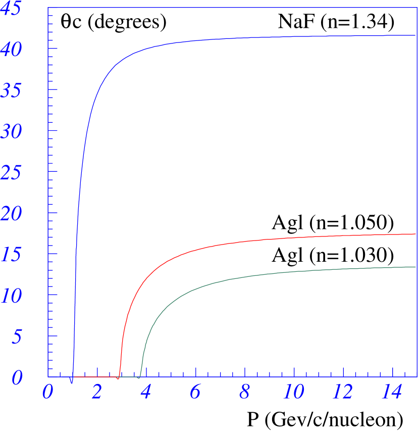
The only solid material with refractive index small enough to allow particle discrimination up to 15 GeV/ per nucleon is aerogel, that is available with refractive indexes of 1.03 and 1.05, and has a maximum Čerenkov angle of about 15 degrees (figure 3).
Due to the small Čerenkov angles obtained with aerogel, a fraction of the particles crossing the radiator in the middle and entering the EMC hole would not be detected by the RICH (track B in figure 4). The Collaboration has still the option to put a small tile of NaF as central radiator: thanks to the wider emission angle of NaF, this would allow for an increase of the effective geometric factor of order 10%.
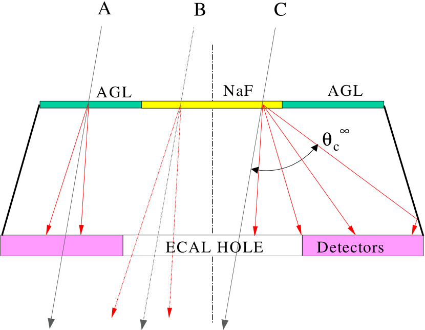
Due to the greater refractive index of Sodium Fluoride, the number of emitted photons is greater than that of aerogel. Hence the width of the radiator would be different: 3 cm for aerogel tiles, 0.5 cm for the NaF core.
2.2 Conical mirror and support structure
The incident angle of charged particles crossing the AMS-02 RICH radiator has a broad distribution (roughly 40 degrees wide), and many events would produce photons not detectable by the pixel plane. For this reason, a conical mirror is foreseen, that will increase the acceptance of about 30%.
The mirror construction is quite elaborate: first, a conical Aluminum mandrel is done whose external surface is lathe machined down to RMS roughness of order 200 nm. Then this surface will be chemically plated with 60 m of Nickel and polished again down to about 10 nm RMS. Finally the mandrel will serve as the “negative” of the mirror, that will be made of a carbon fiber structure 1 mm thick whose internal surface will be plated with Aluminum and finally with a protection layer of quartz or Manganese Fluoride.
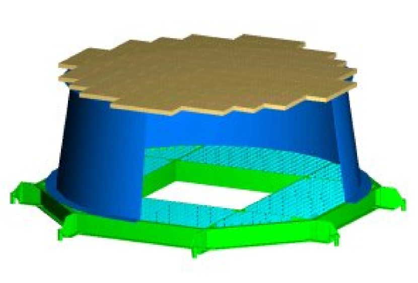
While the radiator support structure (in carbon fiber) is fixed to the TOF mechanics, the mirror and the pixel plane are bound together, with their Aluminum mechanics directly attached to the AMS-02 support structure. Hence, the vibration tests and the finite element method simulations for the radiator are shared with those of the TOF subsystem, while the pixel plane and the mirror have a parallel vibration study. This effort is necessary to follow all NASA specifications, and (both for RICH and TOF) it is carried on in collaboration with the Italian company Carlo Gavazzi Space SpA.
2.3 The phototubes
The pixel plane of the AMS-02 RICH consists of 680 multi-channel Hamamatsu phototubes derived from model R5900. This “venetian blind” R7600-00-M16 model has the photo-cathode divided into cells, followed by 12 metal channel dynodes and a segmented anode with 16 read-out channels.
The photo-cathode cells are wide and the PMT is roughly a square with mm side and mm body height, with 7 mm pins. The voltage divider has total impedance 80 M and the repartition (2.4 : 2.4 : 1 : 1 : 1 : 1 : 1 : 1 : 1 : 1 : 1.2 : 2.4 : 2.4) was chosen in order to achieve a good linearity. Such PMTs have a gain of order at voltages in the range V and their pixel cross-talk is usually below 5%.
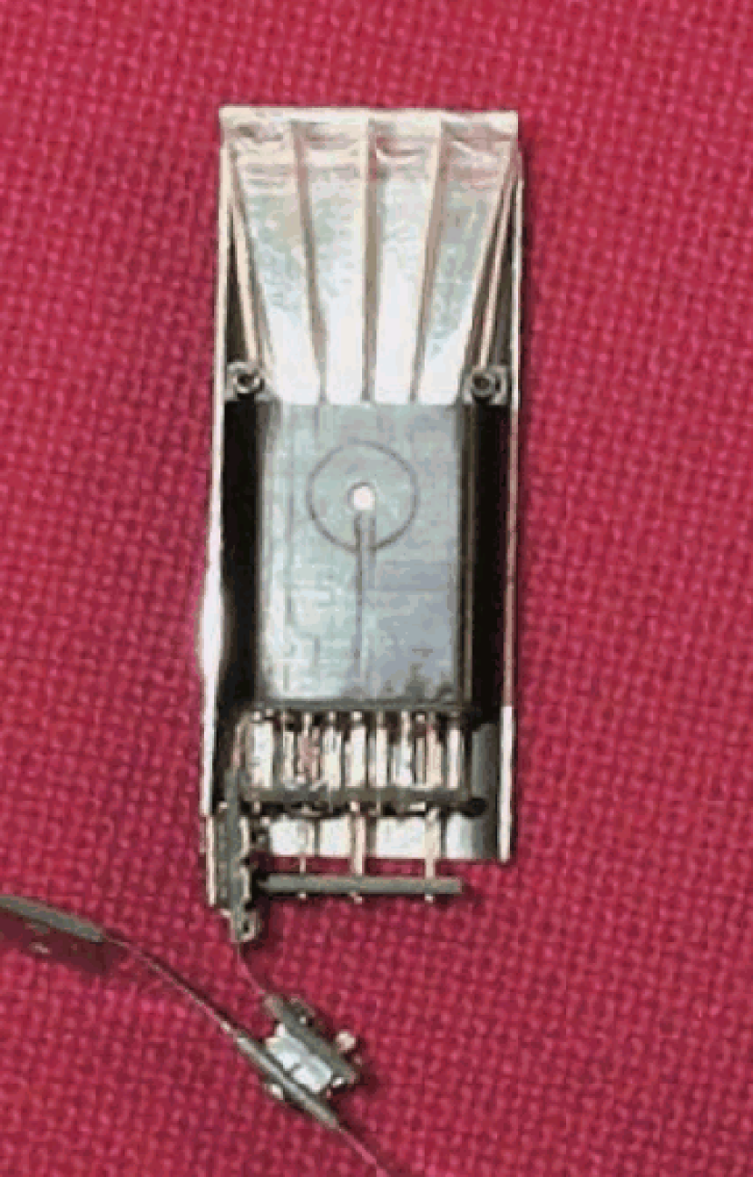
Figure 5 shows a picture of the RICH phototube assembly: the PMT is enclosed by the black housing, to which the plastic light guides are bound with Kevlar wires. The printed circuit boards below the PMT contain the voltage divider and the anodes read-out circuits, connected to an amplifier. Signals from several PMTs are read via a flat cable that is visible in the lowest part of the picture. Finally, half of the enclosing magnetic shielding is shown.
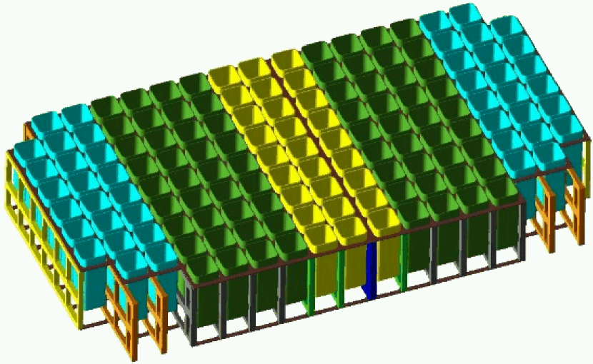
The PMT were tested in magnetic field, with and without magnetic shielding, in order to understand their behavior in the final configuration, and it comes out that the gain will change at most 20% in the worst cases (with G along the AMS direction). In particular, the shielding boxes along the direction will have different thickness (from 6.0 mm to 1.2 mm), in order to compensate for collective effects (figure 6).
3 PROTOTYPE TEST
A prototype for the RICH radiator was built at ISN Grenoble, and used to test different radiators using cosmic ray and beam particles. The prototype (radiator, pixel plane and front-end electronics) is placed inside a vacuum chamber, to avoid environmental light and to ensure that the refractive index between the radiator and the pixel plane is the same as during the ISS operation.
Figure 7 shows the setup used for CR runs: the charged particles that cross both scintillators are tracked by three multi-wire proportional chambers (MWPC), placed above and below the prototype. For beam runs, there are only one MWPC and a couple of thin small scintillators in front of the vacuum chamber, in order to minimize the amount of material placed before the detector.
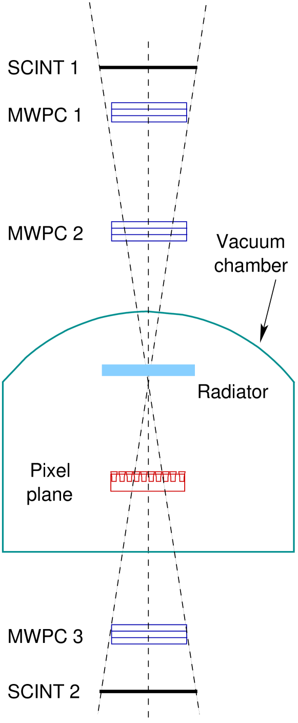
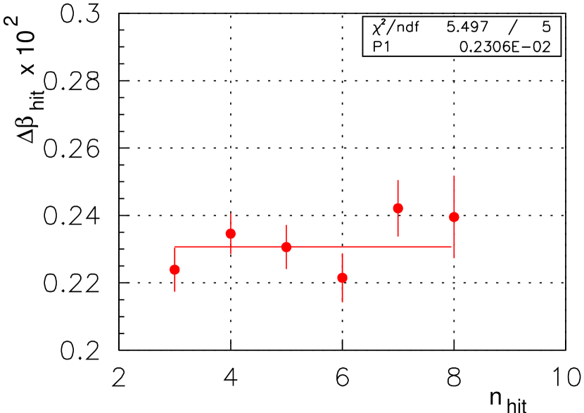
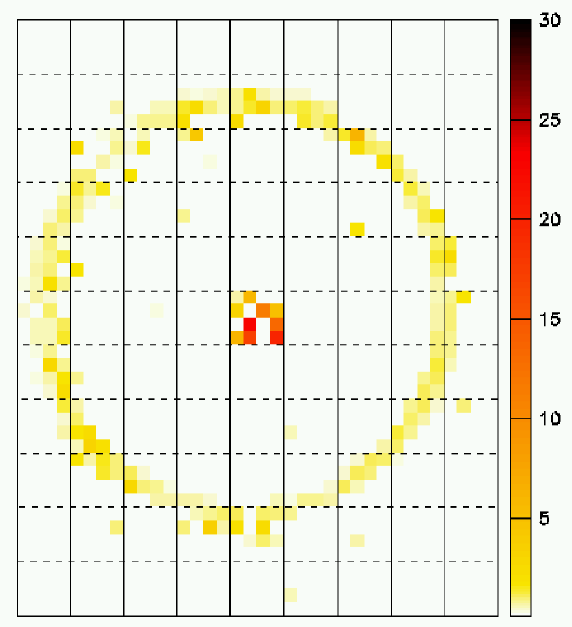
Figure 8 shows the resolution for a given CR event, taking into consideration all used pixels (every hit gives an independent estimate of the Čerenkov angle). On the other hand, figure 9 shows the hits configuration for a Lithium ion during the beam test carried on at CERN during October 2002. During this test the Pb beam accelerated by the SPS was directed on a Be target, and the 20 GeV/nucl fragments were selected by requiring different values for the ratio . The RICH prototype, together with prototypes of the AMS-02 TOF and tracker, collected more than 10 million events with , 3/2 (), 7/4 (), and 1 (protons), and the data analysis is in progress.
References
- [1] S.P. Ahlen et al., “An antimatter spectrometer in space”, Nuclear Instruments and Methods A350 (1994) 351.
- [2] The AMS Collaboration (M. Aguilar et al.), “The Alpha Magnetic Spectrometer (AMS) on the International Space Station, Part I, Results from the test flight on the Space Shuttle”, Physics Reports, vol. 366/6 (Aug.2002), 331-404.
- [3] U. Heinbach and M. Simon, ”Propagation of galactic cosmic rays under diffusive reacceleration”, ApJ 441 (1995) 209-221.
- [4] R. Battiston, ”The gamma-ray detection capabilities of the Alpha Magnetic Spectrometer”, Astropart. Phys. 13 (2000) 13-51.
- [5] M. Buénerd, “Note on the radiator configuration for the RICH of AMS” ISN Report 00/63, AMS note 2000_05_06 (2000).