The NuMI Neutrino Beam and Potential for an Off-Axis Experiment
Abstract
The Neutrinos at the Main Injector (NuMI) facility at Fermilab is under construction and due to begin operations in late 2004. NuMI will deliver an intense beam of variable energy 2-20 GeV directed into the Earth at 58 mrad. Several aspects of the design are reviewed, and potential limitations to the ultimate neutrino flux are described. In addition, potential measurements of neutrino mixing properties are described.
1 Introduction
Within the context of 3-flavor neutrino flavor mixing [1], the atmospheric neutrino experiments [2] have observed oscillations with eV2 and , while solar neutrino experiments[3] indicate eV2 and . Unlike the quark mixing matrix, neutrino mixing appears near-maximal. Only upper bounds [4] exist on the process at the atmospheric . 111The LSND experiment has published evidence[5] for at eV2 which, if confirmed, signficantly modifies the 3-flavor mixing scheme above. If the angle is not zero, and in fact is reasonably large, then the potential exists at conventional long-baseline neutrino beams to measure this rare process and to use it to observe CP violation in the lepton sector and determine the mass hierarchy of neutrinos [6].
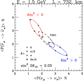
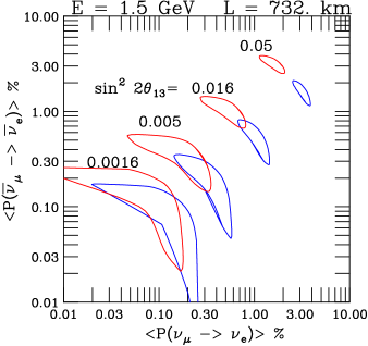
To first order the appearance of in a pure beam in vacuum is given by , which is approximately at the atmospheric . Given the Chooz bounds [4] an experiment to observe this transition must be sensitive at the 1% level. This transition is modified in matter by a factor , where GeV is the resonance energy in the earth’s crust at the atmospheric . Neutrino (antineutrino) transitions are enhanced (depreciated) by this factor under the normal mass hierarchy, while the opposite occurs for an inverted mass hierarchy. This transition is also modified by a factor which depends on the phase of the neutrino mixing matrix, potentially yielding the opportunity to observe a CP-violating difference between and transitions. Figure 1 shows the probabilities for these transitions at an accessible with the NuMI beam.
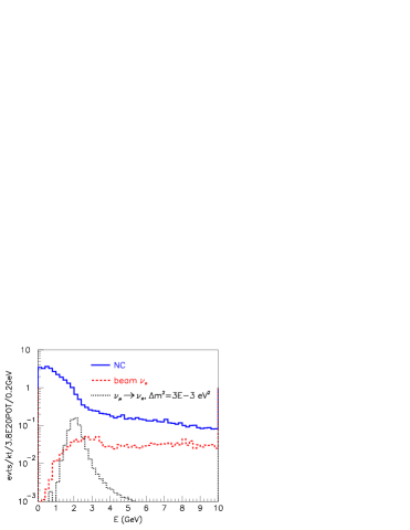
Figure 2 shows the neutrino spectra possible in NuMI[7], both for the initial MINOS experiment[8] on-axis, and at three possible off-axis angles, where the resulting neutrino energy from off-axis pion decays becomes rather narrowly peaked and near-independent of pion energy due to two-body decay kinematics[9]. At 14 mrad, the peak is near oscillation maximum, and the intrinsic from the beam is of order 0.4% under the peak (see Figure 3), coming primarily from muon decays. Of greater magnitude is the potential background to a appearance search from neutral current interactions, which leave a small hadronic visible energy in the detector (see Figure 3). A study of detector designs for an off-axis experiment will be required to assess how frequently these are misidentified as charged current interactions.
The event rate spectra in Figures 2 and 3 are possible with the baseline NuMI beam design, so that if (at the Chooz limit), a 20 kt NuMI experiment at 712 km with similar efficiency and NC rejection as SuperK might observe 86 oscillated ’s in 5 years, with a background of 10 NC’s and 10 intrinsic beam . For JHF [10], the similar numbers are 123 signal, 11 beam , and 11 NC’s in their Phase I. Note that the lower proton beam power at NuMI is mitigated by the higher cross sections for 1.8 GeV neutrinos. To measure matter effects (hence the sign of ) or the phase will require running in mode and additional upgrades to the proton beam intensity from the Main Injector [11] because of the lower antineutrino event rates. Both these measurements benefit from longer baseline distances, again motivating the need for proton intensity upgrades and furthermore larger detectors.


2 The NuMI Beamline
NuMI is a tertiary beam resulting from the decays of pion and kaon secondaries produced in the NuMI target. Protons of 120 GeV are fast-extracted (spill duration 8.6 sec) from the Main Injector (MI) accelerator and bent downward by 58 mrad toward Soudan, MN. The beamline is designed to accept protons per pulse (ppp). The spill repetition rate is 0.45 Hz, giving protons on target per year.
The Main Injector is fed up to 6 batches from the Booster accelerator, of which 5 batches are extracted to NuMI. It is likely that when Main Injector operates at full intensity in multi-batch mode it will have , and emittances up to 40 mm-mrad. Initiatives to produce higher intensity beam from the Main Injector without constructing a proton driver upgrade, including barrier RF stacking of more than 6 Booster batches, could increase the beam intensity by a factor of 1.5 at the expense of some emittance growth.
The NuMI optics will maintain losses below . A recent redesign of the primary beamline replaced a long free drift region with a FODO lattice, increasing the momentum acceptance to at 40 mm-mr. Injection errors of 1 mm lead to targeting errors of 0.5 mm. The beamline has 21 BPM’s of 50 m accuracy, 19 dipole correctors, and 10 retractable secondary emission foil profile+halo monitors.
The primary beam is focused onto a graphite production target [12] of 6.4 20 940 mm3 segmented longitudinally into 47 fins. The target is water cooled via stainless steel lines at the top and bottom of each fin and is contained in an aluminum vacuum can with beryllium windows. It is electrically isolated so it can be read out as a Budal monitor [13]. The target has a safety factor of about 1.6 for the fatigue lifetime of 107 pulses (1 NuMI year) given the calculated dynamic stress of protons/pulse and 1 mm spot size. A prototype target was tested in the Main Injector at peak energy densities exceeding that expected in NuMI. Studies indicate that the existing NuMI target could withstand up to a 1 MW proton beam if the beam spot size is increased from 1 mm to 3 mm [14].
The particles produced in the target are focused by two magnetic ’horns’ [15]. The 200 kA peak current produces a toroidal field which sign- and momentum-selects the particles from the target. The relative placement of the two horns and the target optimizes the momentum focus for pions to a particular momentum, hence the peak neutrino beam energy. The neutrino spectra from two energy settings, called the ’low energy’ (LE) and ’medium energy’ (ME) beams, are shown in Figure 2. To fine-tune the beam energy, the target is mounted on a rail-drive system with 2.5 m of travel along the beam direction, permitting remote change of the beam energy without accessing the horns and target [16]. Measurements on a horn prototype show the expected fall-off of the field to within a percent. The horns are designed to withstand 107 pulses (1 NuMI year), and tests of the prototype horn have so far achieved this.
The particles are focused forward by the horns into a 675 m long, 2 m diameter steel pipe evacuated to 0.1 Torr. This length is approximately the decay length of a 10 GeV pion. The entrance window to the decay volume is a spherical bell-shaped steel window 1.8 cm in thickness, with a 1.5 mm thick aluminum window 1 m in diameter at its center where 95% of the entering pions traverse. The decay volume is surrounded by 2.5-3.5 m of concrete shielding. Twelve water cooling lines around the exterior of the decay pipe remove the 150 kW of beam heating. Earlier plans to instrument the decay volume with a current-carrying wire (called the ’Hadron Hose’ [17]) which would provide a toroidal field that continuously focuses pions along the decay pipe length, have been abandoned due to budget constraints.
At the end of the decay volume is a beam absorber consisting of a 1.21.22.4 m3 water-cooled aluminum core, a 1 m thick layer of steel blocks surrounding the core, followed by a 1.5 m thick layer of concrete blocks. The core absorbs 65 kW of beam power, but is capable of taking the full proton beam power of 400 kW for up to an hour in the event of a mistargeting. In the event of a proton intensity upgrade the core would require no modification, but the steel blocks might require cooling.
Ionization chambers are used to monitor the secondary beam. An array is located immediately upstream of the absorber, as well as at three muon ’pits’, one downstream of the absorber, one after 8 m of rock, and a third after an additional 12 m of rock. These chambers monitor the remnant hadrons at the end of the decay pipe, as well as the tertiary muons from and decays. When the beam is tuned to the medium energy configuration, the pointing accuracy of the muon stations can align the neutrino beam direction to approximately 50 Radians in one spill. Beam tests[18, 19] of these chambers indicate an order of magnitude safety factor in particle flux over the 109/cm2/spill expected in NuMI before space charge buildup affects their operation.
3 Conclusions
The NuMI beam will turn on in 2004, with the first experiment, MINOS, ready to take data. Beyond MINOS, a potential physics program is to exploit the intense NuMI beam in an off-axis experiment, where sensitivities to at the percent level would allow competitive measurements to see if this rare transition is large enough for CP violation studies. Additionally, the NuMI physics program is unique and complements that at the JHF in that matter effects and the neutrino mass hierarchy may be explicitely studied along with the potential CP-violating phase .
References
References
- [1] B. W. Lee, S. Pakvasa, R. Shrock, and H. Sugawara,Phys. Rev. Lett. 38 (1977) 937; B. W. Lee and R. Shrock, Phys. Rev. D16 (1977) 1444; Z. Maki, M. Nakagawa and S. Sakata, Prog. Theor. Phys. 28 (1962) 870.
- [2] S. Fukuda et al., Phys.Rev.Lett. 85:3999-4003,2000; W.W.M. Allison et al., Phys.Lett. B449:137-144,1999; M. Ambrosio et al., Phys.Lett. B517:59-66,2001.
- [3] B. T. Cleveland et al., Astrophys.J. 496:505-526,1998; J.N. Abdurashitov et al., Phys.Atom.Nucl. 63:943-950,2000; M. Cribier et al., Nucl.Phys.Proc.Suppl. 70:284-291,1999; S. Fukuda et al., Phys.Rev.Lett. 86:5651-5655,2001; S. Fukuda et al., Phys.Rev.Lett. 86:5656-5660,2001; Q. R. Ahmad et al., Phys. Rev. Lett. 87:071301,2001.
- [4] M. Apollonio et al., Phys.Lett. B466:415-430,1999.
- [5] C. Athanassopoulos et al., Phys.Rev.Lett. 81:1774-1777,1998.
- [6] A.Para and M. Szleper, “Neutrino Oscillation Experiments Using Off Axis NuMI Beam,” Fermilab-Pub-01-324 (2001); G.Barenboim, D.Harris, et al, “Physics Potential with Stronger Proton Sources,” Fermilab-FN-720 (2002).
- [7] J. Hylen et al. “Conceptual Design for the Technical Components of the Neutrino Beam for the Main Injector (NuMI),” Fermilab-TM-2018, Sept., 1997.
- [8] The MINOS Collaboration, “The MINOS Detectors Technical Design Report,” Fermilab NuMI-L-337, Oct. 1998, S. Wojcicki, spokesman.
- [9] D. Beavis et al., “Long Baseline Neutrino Oscillation Experiment, E889, Physics Design Report,” BNL-52459, April, 1995
- [10] Y. Itow et al., “The JHF-Kamioka Neutrino Project”, Letter of Intent, KEK Report 2001-4, ICRR Report 477-2001-7, TRIUMF Report TRI-PP-01-05, June, 2001.
- [11] “Proton Driver Design Study,” W.Chou and B.Foster (eds.), Fermilab-TM-2136 (2000) and Fermilab-TM-2169 (2002).
- [12] A.G. Abramov et al, Nucl. Instrum. MethodsA485, 209 (2002).
- [13] K.Budal, IEEE Trans. Nucl. Sci. 14, 1132 (1967).
- [14] M.A.Kostin, V.I.Balbekov, N.V.Mokhov, and Z.Tang, Fermilab-Conf-02/107 (2002).
- [15] S. van der Meer, CERN Yellow Report CERN-61-07 (1961).
- [16] M.Kostin, S.Kopp, et al, “Proposal for Continuously Variable Beam Energy,” Fermilab note NUMI-BEAM-0783.
- [17] J.Hylen et al, “The Hadron Hose: Continuous Toroidal Focusing for Conventional Neutrino Beams,” Fermilab-Pub-02/105-E, accepted for publication in Nucl. Instrum. Methods.
- [18] D. Naples et al, submitted to Nucl. Instrum. Methods.
- [19] R.Zwaska et al, submitted to Nucl. Instrum. Methods.