Track Timing at Linear Colliders with a Silicon Drift Detector Main Tracker
Abstract
The track timing capabilities of a silicon drift detector based tracker for a future linear electron-positron collider are evaluated. We show such a detector can time tracks at the nanosecond, and for high-, sub-nanosecond level. This implies that, even for collider designs with the bunch spacing at 1.4 , every track can be assigned to a particular bunch crossing at a confidence level of up to two standard deviations. We suggest a choice for the drift axes in the tracker layers to simultaneously optimize the momentum resolution and track timing.
keywords:
linear collider; NLC; JLC; TESLA; Tracking; Silicon drift detector; Pile-up; Timing.WSU-HEP-0206
, , ††thanks: Corresponding author. Phone: (313)–577–2781; fax: (313)–577–0711; e–mail: rykov@physics.wayne.edu
PACS: 29.40.Vj; 29.20.Dh
1 Introduction
Projects for future linear colliders (LC) operating at = 0.5–1 TeV [1, 2, 3] consider a number of detector layouts [4, 5]. For example, the NLC proposal [4] includes two options for the high-energy interaction region (IR) which are called Large, L; Silicon Detector, SD; and one for a low energy second IR called Precise, P. The tracking systems in all three layouts include a high-resolution pixel vertex detector (VXD), but differ significantly in the technology choices for the main tracker (MT). The central MTs for the L- and P-configurations are based on large-volume time projection chambers (TPC). In the SD-version, the central MT consists of few tracking layers of either silicon drift (SDD), or silicon strip detectors.
In all three detector layouts, drift detectors with three-dimensional space point measurements along charged particle trajectories are considered as either the only (TPC), or one of few alternative solutions (SDD) for the central MT. Drifting of generated electron clouds in the TPC and SDD is rather slow. This leads to their long sensitivity to ionization which ranges from a few to a few tens of microseconds. Therefore, tracks from the event of interest will coexist in the raw data with tracks from events which occurred at some time before and after the trigger. These tracks need to be recognized and separated from the triggered event.
The time structures of collisions at the various proposed high energy LCs are expected to be similar, but differ in detail. All three projects feature trains (Rf-pulses) of and bunches. At NLC/JLC, each train will consist of 190 bunches, separated by 1.4 , resulting in a train duration of 265 . TESLA features 950 long trains of 2800 bunches separated by 337 . The projected Rf-pulse repetition rates at NLC, JLC and TESLA are 120, 100 and 5 , respectively. The design luminosities in all three proposals are on the order of (2–3)1034 .
According to the estimates of Ref. [4] for the design luminosity, 2.2 hadronic events/train, on average, will occur at the NLC/JLC in addition to the trigger. The average number of tracks is 17 with 100 deposit in the calorimeter per such an event. All tracks from these events, along with the trigger, will be present in a TPC or SDD based MT simultaneously during an ionization drift, which is considerably longer than the NLC/JLC train time-length111Due to the low Rf-pulse repetition rates, there will be no more than one train per SDD or TPC drift cycle, though.. At TESLA, there will be 0.02 hadronic events per bunch crossing [6, 4], and ionization from only a fraction of a single train will be present simultaneously in the SDD or TPC. These transfer into 0.5 background events occurring during the SDD drift of 7–8 , and 3–5 events during the 50–60 long TPC drift in L- and P-versions of the detector. In all cases, the beamstrahlung background from bunch crossings will also be present in the trackers. It is recognized [4] that, if the time stamping for the tracks in the TPC or SDD is not done, it could seriously impact the detector performance, particularly its missing mass resolution.
Matching tracks in the TPC or SDD to the collision region and/or the VXD provides some time stamping. However, this does not work for secondary tracks from decays of long lived particles. Also the VXD, located at a small distance to the collision region, has a much higher occupancy of hits from low- tracks produced by beamstrahlung, making matching more difficult. Therefore, it is more desirable to find a solution that uses information from only the MT. In the case of a TPC, it was suggested to place at some TPC depth a fast intermediate tracker, constructed from scintillating fibers, and alternatively or in addition, a silicon intermediate tracking detector just inside the TPC inner radius [4]. A similar solution may also be possible for a SDD based tracker. However, due to the finer segmentation of the SDDs and more flexibility in the choices for SDD drift axes in MT layers, such special time-stamping layer(s) will not be necessary if a silicon drift detector is chosen as the technology for the central MT.
2 SD main tracker layout and simulation model
2.1 SDD based main tracker
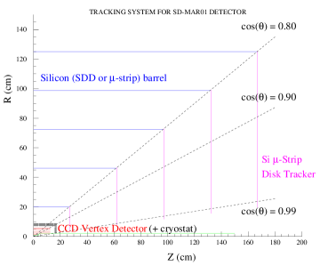
The tracking system of the proposed SD option [4, 9] with the 5 strong magnetic field is schematically shown in Fig. 1, left. Its central and forward MTs consist of a 5-layer silicon barrel, made of either silicon drift or micro-strip detectors, and five layers of double-sided silicon micro-strip forward disks, respectively. The layers of the central MT barrel are located at radii from 20 to 125 . The 5-layer CCD vertex detector is located closer to the collision region at radii from 1.2 to 6 .
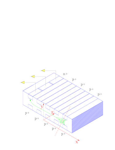
The SDD based version of the central MT will be comprised of 6000 SDDs of 1010 area and thickness 150–200 each. A two-dimensional position of a particle hit in the SDD wafer is measured as follows [10] (see SDD schematic view in Fig. 1, right). After passage of an ionizing particle through the SDD, the created electron cloud is within 5–10 confined to a 10–20 thick “pancake” around the SDD middle plane. At the same time, the cloud starts drifting along the -axis222The reference frame of Fig. 1, right, is used here and to the end of Sec. 2.1. in the uniform electric field 40-50 , applied to the SDD, with a constant velocity 6-7 . The electron cloud eventually drifts to the anodes, located at the SDD edge. The SDD anodes are spaced every 100–300 (for the LC detector, the exact spacing is still to be optimized). The -position of a particle crossing is determined by measuring the time delay between the trigger and anode signals, and the -position is determined from the signal distribution over hit anodes. An estimate for the practically achievable spatial resolution of the SDD based tracker along the anodes (-axis) is 5–7 . The resolution in the drift direction (-axis) is expected to be somewhat worse, at about 8–10 , due to drift nonlinearities caused by defects in material, environmental effects and calibration uncertainties.
In order to reduce the maximum voltage on a wafer, previous designs [11, 12] feature a “double-SDD”, i.e. wafers consisting of two SDDs, drifting along the same axis but in opposite directions. The SDD anodes are located at the two opposite edges of the wafer, and high voltage, creating the drift field, is applied in the middle of the wafer at . The alteration of the drift direction within such small MT pieces, as each single SDD wafer, represents a powerful tool to discriminate tracks by their generation time. The other handle for doing this is the alteration of the drift axes in the MT layers, which is also evaluated in this paper.
2.2 Simulation model
For the studies presented here, a simplified model of the SD tracking system has been used. In this model, five parallel SDD layers of a thickness, equal to 0.5% of radiation length each were located at distances of 20, 46.25, 72.5, 98.75 and 125 from the beam-line. The SDD drift velocity, , has been assumed to be 6.75 , which corresponds to a drift electric field of 50 . Five layers of the CCD based VXD of a thickness, equal to 0.12% of radiation length each were placed at distances of 1.2, 2.4, 3.6, 4.8 and 6 . For more SD setup details see Ref. [9].
Particle trajectories in the SD uniform, 5 strong magnetic field have been generated, taking into account small angle multiple scattering in the detector material, including the beam pipe, VXD cryostat, air, etc. Ionization and radiative energy losses have been ignored. The positions of the track crossing points in each VXD and MT layer have been randomly Gaussian smeared with the expected position resolutions: 5 for the VXD along the both axes; 7 for the SDDs along anodes; and 10 for the SDDs along ionization drift. Tracks were generated within the kinematics region of 0.8, where is the polar angle. The event vertex position, if used, has been assumed to be known to 2 for both, transverse and longitudinal, directions.
In the least squares method of the helical trajectory reconstruction, the full initial covariance matrix has been used, taking into account the cross-correlations of the track crossing points in the VXD and MT layers due to multiple scattering.
3 Simulation results
3.1 Discrimination of tracks from event pile-up
In these simulations, we assume that, for the charged particles produced in the triggered event, the event time and positions of track crossing points in the MT layers were measured correctly. Then, at the track reconstruction stage, the hit set, created by each single
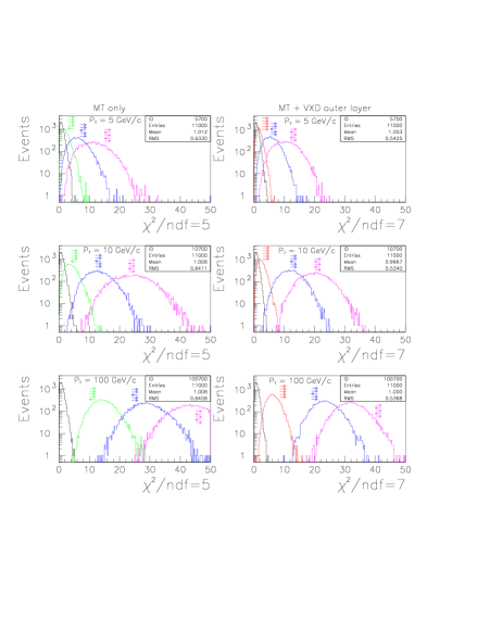
particle, will match to a single track, yielding a good fit with within an expected range. For a track emerging before or after the trigger by the time shift of , the assumption of its belonging to the triggered event will lead to a misplacement of its layer crossing points by along the drift axis. In the cases of at least one hit in some layer drifting in the opposite direction compared to the others, the hit set will not match to a single track and, thus the hypothesis that this potential track belongs to the triggered event would be rejected. As an illustration, in Fig. 2 the simulated -distributions for 10 are compared to the ones with correct track timing for some combination of drift directions in the SDD layers, all drifting along -axis333i.e. along detector magnetic field; here we switched to the detector global coordinate system as shown on the left side of Fig. 1..
In the 5-layer MT with all SDDs drifting along the same axis, a particle may encounter 16, roughly equally probable, distinct combinations of the relative drift directions in the MT layers. In 15 of these combinations, at least one hit drifts in the opposite direction than the others. This means that, in 15/16 = 93.75% cases, the selection procedure above will work. Only the relatively small fraction, 1/16 = 6.25% of tracks will cross the SDDs, drifting in the same direction, and the respective out-of-time hits will still match to a single track, but shifted as a whole from the true particle trajectory by . In many cases, this shift can be detected by matching the track to the VXD and/or the collision region, and we can decide if the track should be associated with the triggered event (see right column of Fig. 2).
A way to avoid the necessity of using measurements beyond the MT for sorting out all tracks in the pile-up is to let SDDs in different layers drift along different axes: some drifting along the
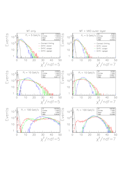
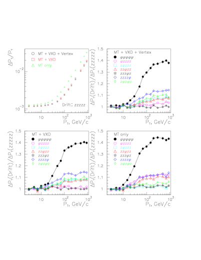
detector magnetic field (-axis) as in AGS E896 [11], but others drifting along the azimuth as in STAR at RHIC [12], i.e. along -axis. In Fig. 3, some choices for the drift axes in MT layers are compared to each other. Apparently, the best track discrimination by their generation time is achieved by alternating drift axes from layer to layer, like (or , which is similar but is not shown in Fig 3). But even the options with only one layer drifting perpendicularly to the other four provide much better results, particularly for the “MT only”, compared to the case of all layers drifting along the same axis444We do not consider here another possible solution with all SDDs drifting along the same axis, but with significantly different drift velocities in different layers..
The advantages of choosing some MT layers to drift along the azimuth should be weighted against a potential worsening of the momentum resolution due to the expected differences in the SDD spatial resolutions along anode and drift axes. In Fig. 4, the various choices for the drift axes in the MT layers are compared with respect to the momentum resolution. For the most important cases of “MT+VXD+Vertex” and “MT+VXD”, the best drift combination for the track discrimination, , would lead to a loss in at the highest momenta by 10% compared to the best achievable resolution with -drift. However, the combinations and affect the momentum resolution by less than 2%, if at all. For the “MT only”, the choice of would also be one of the two best. The other combination is , but it is not among the best for the momentum resolution, using the VXD and/or vertex. As a result, at least two choices for the drift axes in the MT layers, and , should seriously be evaluated as a good compromise between momentum resolution and track time stamping.
3.2 Track timing
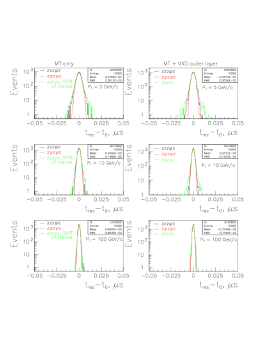
An additional parameter, track generation time, can be introduced in the track fits. With this parameter derived from the fit, each track could be assigned to an appropriate event with the well known generation time, which has been accurately measured, using the dedicated fast sub-detector(s). Fig. 5 shows the simulated distributions for the differences of the reconstructed, , and actual track generation time, , for three choices of drift axes in the MT layers. One observes that the widths of the distributions (RMS) are on the nanosecond scale, but for high- tracks, time resolution in the sub-nanosecond range seems to be achievable.
The most promising choices for the drift axes in the layers are compared in Fig. 6. Apparently, the combination is always the best. However, the choice with the only one layer, drifting along the
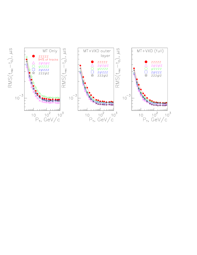
azimuth, is hardly distinguishable from , if the VXD is used, and just slightly worse for the MT only case. Combined with the earlier observation of virtually no negative impact of the combination on the momentum resolution, this option should be very seriously considered for the design of the SDD based central MT.
4 Conclusion
We have shown that, with an SDD based central MT for the detector at the linear collider, the track selection and timing is possible at the nanosecond and even sub-nanosecond level. This means that, even at the NLC and/or JLC with the bunch spacing at 1.4 , each high- track can be assigned to a particular bunch crossing at a confidence level of up to two standard deviations.
In order to achieve a good track timing and a minimal effect on the momentum resolution in the proposed 5-layer central MT, we suggest a design with four layers drifting along the magnetic field (-axis), and one layer drifting along the azimuth (-axis) with virtually no negative impact of such a choice on the detector momentum resolution.
It is worth underlining that with the SDD based MT, the track timing capabilities on the sub-nanosecond scale are built into the technology choice at no additional cost or effort.
5 Acknowledgments
It is our pleasure to thank K. Riles and B. Schumm for the useful communications on the linear collider tracking system characteristics and design, and J. Balewski, G. Bunce and A. I. Pavlinov for the inspiring discussions. This work has been supported in part by the DoE and NSF.
References
- [1] The NLC Collaboration, Report on the NEXT LINEAR COLLIDER (A Report Submitted to Snowmass ’01, Gen. Ed. N. Pinney), FERMILAB-Conf-01/075-E, LBNL-PUB-47935, SLAC-R-571, UCRL-ID-144077, June 2001; International Study Group Progress Report on Linear Collider Development, Ed. N. Toge, KEK Report 2000-7, SLAC-R-559, April 2000.
- [2] JLC Design Study Group, JLC Design Study, Editor N. Toge, KEK Report 97-1, 1997.
- [3] TESLA Technical Design Report, DESY 2001-011, March 2001.
- [4] T. Abe, et al. (American Linear Collider Working Group), Linear Collider Physics Resource Book for Snowmass 2001, BNL-52627, CLNS 01/1729, FERMILAB-Pub-01/058-E, LBNL-47813, SLAC-R-570, UCRL-ID-143810-DR, May 2001.
- [5] K. Abe, et al. (ACFA Joint Linear Collider Physics and Detector Working Group), Particle Physics Experiments at JLC, ACFA Linear Collider Working Group Report, 2001, hep-ph/0109166.
- [6] C. Hensel, LC-DET-2000-001, 2000.
- [7] W. B. Christie, STAR Note 168, 1994 (at www.star.bnl.gov).
- [8] V. L. Rykov, STAR Note 237, 1996 (at www.star.bnl.gov).
- [9] B. Schumm, Report to the US Linear Collider Workshop, John Hopkins University, March 2001 at http://scipp.ucsc.edu/schumm/#A (see also http://www-mhp.physics.lsa.umich.edu/keith/LC/baselines_mar01.html).
- [10] E. Gatti and P. Rehak, NIM A289 (1990) 410.
- [11] S. U. Pandey, et al., IEEE Trans. Nucl. Sci. 47 (2000) 2114.
- [12] R. Bellwied, et al., NIM A439 (2000) 497.