The Time of Flight System of the AMS-02 Space Experiment
Abstract
The Time-of-Flight (TOF) system of the AMS detector gives the fast trigger to the read out electronics and measures velocity, direction and charge of the crossing particles. The new version of the detector (called AMS-02) will be installed on the International Space Station on March 2004. The fringing field of the AMS-02 superconducting magnet is kG where the photomultiplers (PM) are installed. In order to be able to operate with this residual field, a new type of PM was chosen and the mechanical design was constrained by requiring to minimize the angle between the magnetic field vector and the PM axis. Due to strong field and to the curved light guides, the time resolution will be ps, while the new electronics will allow for a better charge measurement.
1 Introduction
The Alpha Magnetic Spectrometer (AMS) [1] has been redesigned to increase the maximum detectable rigidity up to , by using a superconducting magnet which will provide a maximum field of about . The new Time Of Flight (TOF) system of the experiment has to operate in a stronger magnetic field and with many different inclinations between the photomultiplier (PM) axis and the field direction. In the following a description of the new TOF system is given and results are reported on various aspects of the system operation.
The main constraints for the TOF sub-detector are due to the operation in space: the counters must be housed into mechanically robust and light tight covers; the whole system has to follow the NASA specifications for the support structure (resistance to load and vibrations); all the TOF electronics must be protected against possible faults due to the highly ionized low-orbit environment and must have complete control on every channel for fine tuning during 3 years of data taking. The power consumption is limited to 150 W for the whole TOF system.
2 The new AMS spectrometer and the new TOF design
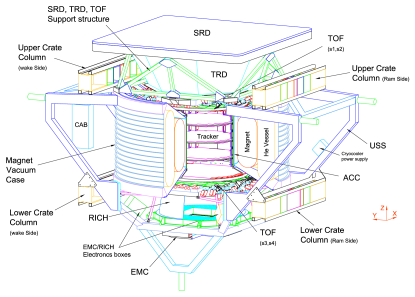
Figure 1 shows the new version of the AMS detector (called AMS-02) that will be installed on the ISS in 2004. The AMS-02 spectrometer will make use of a superconducting magnet (0.8 T dipolar field); the tracker will have 8 Si planes, to achieve better rigidity resolution; there will be a RICH to extend to higher energies the TOF measurement range, while a TRD and an electromagnetic calorimeter will improve the capability to distinguish between electrons and protons up to hundreds GV rigidity.
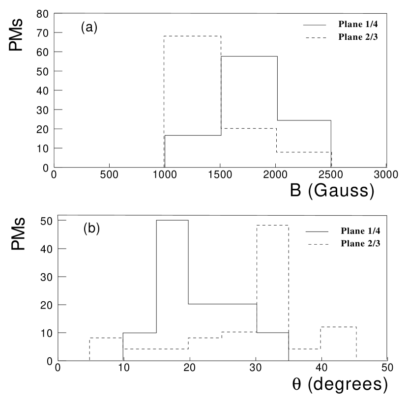
The new TOF is being completely designed and built at the INFN Laboratories in Bologna. Its main goals are to provide the fast trigger to AMS readout electronics, and to measure the particle velocity (), direction, position and charge. The mechanical constraints of the AMS-02 apparatus do not allow to minimize the PM orientation with respect to the direction of the magnetic field for all the TOF counters (see figure 2). A fine mesh PM (Hamamatsu R5946), specifically designed to operate in strong magnetic field, has been chosen for the TOF counters, and thus tested for time resolution and pulse height response in magnetic field.
3 Tests in magnetic field of the new TOF phototubes
A red diode has been used to test the response of the PMs, whose light was guided to the photomultiplier tube by two optical fibres. The tube was placed inside the poles of an electro-magnet (maximum field kG) on a movable stand which can be rotated at a maximum angle of with respect to the magnetic field. The charge signal from the photomultiplier was digitized by an ADC and registered by a PC-based data acquisition system.
3.1 PM gain and single photoelectron response
Three PMs, operating with a gain of at 1700, 2000 and 2200 V respectively, were tested in magnetic field. The PM responses have been measured for different values of the magnetic field and of the angle between the tube axis and the field direction . The single photoelectron resolution [4] has been measured using a very low-level light pulse from the LED, at several tube orientations and field magnitudes. It is about 70% at , but it degrades rapidly with increasing magnetic field at fixed angles and with increasing angle at fixed magnetic field. The consequence of the worsening of is a small degradation in the resolution of the energy measurement. No relevant difference is seen between the three tubes.
3.2 Time resolution from data and Simulation of time response
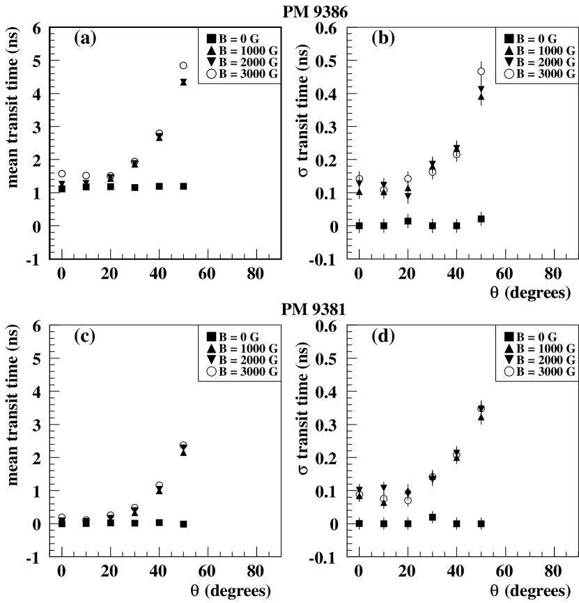
Figure 3 shows the mean transit times (i. e. the time delay with respect to the LED pulse) and the time resolutions for tubes no. 9381 and 9386, as function of the magnetic field and for different values of (the times plotted are relative to the time at of PM 9381). The most relevant observation is that the tube operated at highest voltage (no. 9381) shows the shortest transit time and the best time resolution. The transit time generally gets worse with increasing angle for both PMs, but it is more critical for the PM working at lowest voltage (no. 9386).
The fine mesh PM time response in magnetic field has been simulated by solving the Lorentz equation of motion for the photoelectrons,[5] making use of the Runge-Kutta numerical approximate solution in finite time intervals.[6] We followed the energy distribution of the secondary electrons emitted (SEE) at the dynodes given also by Barbiellini et al. (1995).[7] Finally we got a distribution of time of arrivals at the anode as a function of and , for different simulated HV.
Figure 4 shows our simulation of the fine mesh time response compared to the data (time relative to the time at of the lowest gain PM). The worsening of the transit time with respect to the angle , both experimental and simulated, is most critical for the PM working at lowest voltage (no. 9386) and this is also true for the measured time dispersions (see figure 3).
4 Electronics
The TOF has 4 planes with 12 counters seen by 2 PMs at each side, for a total of 192 PMs. The signals from the two PMs on each side of the scintillator paddle will be summed to provide one signal from the anodes and one from the last dynodes. The anode signals will be used for time measurement, while the dynode signals will be used for charge measurement using linear ADCs. The TOF electronics will be housed in two pairs of crates, each pair servicing one pair of planes and containing the PMs power supplies and the read-out electronics.
Each electronics crate will feed independently the 24+24 (odd and even) PMs of two different half TOF planes, in order to guarantee the necessary redundancy. In addition the doubly redundant data acquisition boards will read 24+24 channels (anodes and dynodes) per crate.

5 Conclusion
The AMS-02 TOF system will have a worst time resolution than in AMS-01, due to the tilted light guides and to the effect of the magnetic field. In particular, several of the PMs will have an angle with respect to the magnetic field direction greater than and thus quite low performances. The expected resolution in in the worst case, when only two planes are used to compute , would be (at =1) and positrons could be identified against protons up to about GeV.
References
- [1] The AMS Collaboration, Phys. Lett. B 461 (1999) 387-396; Phys. Lett. B 472 (2000) 215-226; Phys. Lett. B 484 (2000) 10-22; Phys. Lett. B 490 (2000) 27-35; Phys. Lett. B 494 (2000) 193-202.
- [2] D. Alvisi et al., Nuclear Instruments and Methods A 437 (1999) 212–221.
- [3] W.R. Leo, “Techniques for Nuclear and Particle Physics Experiments”, Springer–Verlag (1987).
- [4] B. Bencheick et al., Nucl. Instrum. and Methods A315(1992) 349.
- [5] L.Brocco et al.,”Behavior of Photomultiplers in strong magnetic field for the TOF system of the AMS-02 Space Experiment” ICRC-2001 proceedings.
- [6] W. Hpress et al., “numerical Recipes in Fortran 77: The Art of Computing”, Cambridge University Press, also avaiable at the url: http://www.nr.com/.
- [7] G.Barbiellini et al., “A simulation study of the behaviour of fine mesh photomultipliers in magnetic field ” A 362 (1995) 245-252.