SLAC–PUB–8774
Feb 2001
LCD ROOT Simulation and Analysis Tools ***Work supported by Department of Energy contract DE–AC03–76SF00515 (SLAC).
Masako Iwasaki
Department of Physics, University of Oregon, Eugene, OR 97403-1274, USA
Toshinori Abe
Stanford Linear Accelerator Center, Stanford CA 94309, USA
Abstract
The North American Linear Collider Detector group has developed a simulation program package based on the ROOT system. The package consists of Fast simulation, the reconstruction of the Full simulated data, and physics analysis utilities.
Presented at the 5th International Linear Collider Workshop (LCWS 2000), 24-28 Oct 2000, Fermilab, Batavia, Illinois, USA
1 Introduction
For the various studies of the future Linear Collider experiments, the North American Linear Collider Detector group (LCD) has constructed a simulation facility. It consists of two kinds of detector simulators, Full and Fast simulators, designed for detailed detector studies and physics analyses, respectively. We use the GISMO package[1] for the Full simulation. Using the digitized outputs from the Full simulation, we reconstruct charged tracks and clusters. The Fast simulation is based on parametrized position and energy smearing, and it makes tracks and clusters directly from the generated particle information.
In the LCD group, we have developed two object-oriented program packages based on JAS/Java[2] and Root/C++[3], for the reconstruction of the Full simulated events, the Fast simulation and the event analysis. In this report, we introduce the simulation and analysis package based on Root/C++.
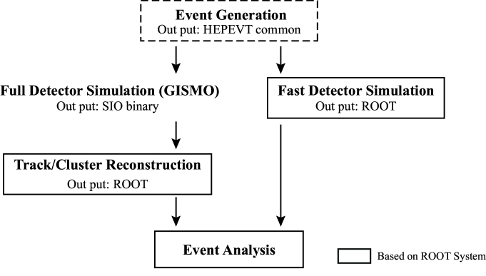
Fig.1 shows the LCD simulation and analysis flow using ROOT. We use a standard HEPEVT format using the FNAL StdHep 4.06 I/O package[4], for the generator output and the detector simulator input. The output format of the Fast simulator is the Root binary, it is also possible to be linked with the event analysis directly. The output format of the Full simulator is the SIO binary and is converted to the Root binary. Then its reconstruction and the event analysis are done based on the LCD Root system.
2 Simulation and Event Reconstruction
There are two detector models presently under study by the LCD group, a Small and a Large detector. The detector parameters are listed in Table 1. The Small detector is a compact detector featuring a very strong magnetic field and solid-state tracking device. The calorimeter is also compact and made with Si-W. The Large detector has a much larger tracker (TPC) with lower magnetic field and Pb-scintillator calorimeter. Both detectors are designed to have a CCD Vertex Detector. These detector parameters are used for both Full and Fast simulations.
| Small | Large | |
| Vertex Detector | CCD | CCD |
| Impact parameter resolution | ||
| Central Tracking | Si micro strips | TPC |
| Momentum resolution (High) | ||
| (Low) | ||
| Electromagnetic Calorimeter | W/Si pads | Pb/scintillator |
| Barrel Inner Radius | 75 cm | 200 cm |
| Endcap Inner Z | 150 cm | 300 cm |
| Energy resolution | ||
| Granularity | 20 mrad | 20 mrad |
| Hadron Calorimeter | Cu/scintillator | Pb/scintillator |
| Barrel Inner Radius | 140 cm | 250 cm |
| Endcap Inner Z | 186 cm | 350 cm |
| Energy resolution | ||
| Granularity | 60 mrad | 60 mrad |
| Coil Magnet | ||
| Magnetic field | 6 Tesla | 3 Tesla |
| Inner Radius | 100 cm (outside EM Cal) | 376 cm (outside HAD Cal) |
In the Fast simulation, charged particles within the magnet field follow helical trajectories, and their momenta and positions are smeared. Here the charged tracks are expressed by 5 parameters, and are smeared with a 55 covariant error matrix.
Electrons, photons, and hadrons produce clusters in the electromagnetic (EM) and hadronic (HAD) calorimeters. Here, one cluster is made from one particle. Energies and positions of clusters are smeared. We assume transverse position resolutions of 1cm/ (electrons and photons) or 5cm/ (hadrons). To consider the detector granularity and cluster width, which is typically a few units of Moliere radius, we merge the clusters when the angular separation between clusters is less than , where is a size of the detector granularity.
The position of the interaction position is also smeared. We assumed ==2 m and =6 m. The determination of these values are described in Ref.[6].
In the reconstruction of the Full simulated data, we postpone the track reconstruction. Instead, we make charged tracks by smearing, using exactly the same procedure as in the Fast simulation, but we also apply a minimum tracker-hit cut. Calorimeter clusters are made by gathering the hits which are from the same particle. Energy and position of the cluster is obtained from the energy sum, and the energy-weighted average of associated Calorimeter hits, respectively.
Comparing the Full and Fast simulations, the most significant difference is in the Calorimetry. It is important to improve the parameterization of the Fast simulator Calorimetry to have a more realistic detector response, which we hope to implement in the near future.
3 Event Analysis Tools
For the physics analysis, there are several useful tools in the LCD Root program. We provide Thrust finding and 3 kinds of Jet finding (based on JADE, JADE-E and DURHAM algorithms) programs.
A topological vertex finding algorithm is developed in the SLD experiment[5]. Here the secondary vertices are reconstructed with charged tracks by searching the space points where track density functions overlap in the 3D space. The original SLD prepmort program, called ZVTOP, is translated into C++ and several parameters are set for the LCD studies. Based on the topological vertex finding, we get excellent performances on heavy-quark (both and ) tagging and charge identification of the quark. The details are described in Ref.[6]. There are physics studies which use the topological vertex finding in these proceedings[7].
In the energy flow analysis, neutral clusters are selected by the absence of a track and cluster association. For this analysis, we provide methods which extrapolate the particles to the cluster cylindrical radius.
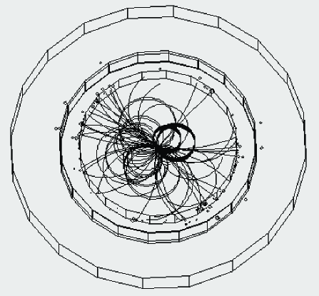
As a graphical tool, there is an event display for the LCD Root program. An example of the event view for a event is shown in Fig.2
4 Summary
In this report, we briefly introduce the simulation and analysis tools based on ROOT for the LCD group. Although the tools are constantly being improved, they can be obtained via the URL,
http://www-sldnt.slac.stanford.edu/nld/New/Docs/LCD_Root/root.htm.
Feedback from the users is highly welcomed.
References
- [1] T.H. Burnett, “Gismo: An Object-Oriented Approach to Particle Transport and Detector Modeling”, Proceedings of the International Conference of Monte Carlo Simulations in High Energy and Nuclear Physics, Tallahassee, FL, 1993.
- [2] G. Bower et al., ”Java Based LCD Reconstruction and Analysis Tools”, these proceedings.
- [3] R. Brun and F. Rademakers, Nucl. Inst. Meth. A389 81 (1997).
- [4] StdHep: http://www-pat.fnal.gov/stdhep.html.
- [5] D. Jackson, Nucl. Inst. Meth. A388 247 (1997).
- [6] T. Abe, “A Study of Topological Vertexing for Heavy Quark Tagging”, these proceedings.
- [7] J. Brau et al., “Higgs Branching Ratio Measurements at a Future Linear Collider”; and M. Iwasaki, “Study of Top-quark Production and Decay Vertices with LCD Fast Simulation”, these proceedings.