Measurement of Optical Response of a
Detuned Resonant Sideband Extraction Interferometer
LIGO-P060007-00-R
Abstract
We report on the optical response of a suspended-mass detuned resonant sideband extraction (RSE) interferometer with power recycling. The purpose of the detuned RSE configuration is to manipulate and optimize the optical response of the interferometer to differential displacements (induced by gravitational waves) as a function of frequency, independently of other parameters of the interferometer. The design of our interferometer results in an optical gain with two peaks: an RSE optical resonance at around 4 kHz and a radiation pressure induced optical spring at around 41 Hz. We have developed a reliable procedure for acquiring lock and establishing the desired optical configuration. In this configuration, we have measured the optical response to differential displacement and found good agreement with predictions at both resonances and all other relevant frequencies. These results build confidence in both the theory and practical implementation of the more complex optical configuration being planned for Advanced LIGO.
pacs:
42.60.-v, 42.60.Da, 95.55.Ym.Currently the first generation of ground-based laser interferometric gravitational wave (GW) observatories, including LIGO Sigg02 , VIRGO Fiore02 , GEO Willke02 and TAMA Ando02 , are in operation. Together, they form a global network for the detection and study of GWs and their astrophysical sources. However, more sensitive detectors are required in order to detect significant numbers of sources. Advanced LIGO M990288 ; M990080 is one of the next-generation of planned gravitational wave detectors which currently plans to employ a detuned signal mirror in order to manipulate and optimize the frequency response of the detector. Such configurations hold the possibility of circumventing Buonanno01a ; Buonanno01b ; Buonanno02 the free-mass Standard Quantum Limit (SQL) on the measurement of small displacements Braginsky68 at frequencies between those where shot noise dominates and those where radiation pressure noise dominates.
Long-baseline gravitational wave detectors are based on Michelson interferometers, which are designed to be sensitive to small differential displacements of the arms. The Initial LIGO, VIRGO, and TAMA300 detectors add Fabry-Perot resonant optical cavities in the arms, and a power recycling cavity formed from a mirror between the laser and the Michelson, to enhance the optical gain of the displacement measurement. The next generation of detectors aims to improve on the sensitivity by making use of higher-powered lasers and more complex optical configurations.
Signal recycling (SR) was proposed by Meers Meers88 as a means to reduce the shot noise contribution to the displacement signal over a narrow band near DC. By using a signal mirror at the asymmetric port of the Michelson to form a signal recycling cavity, the storage time of the signal sidebands can be increased, leading to enhanced sensitivity near DC but reduced sensitivity at higher frequencies; the detector bandwidth is reduced. Thus, it is most effective to use this technique with interferometers whose arms are optical delay-lines (such as GEO) or low-finesse cavities. High-gain power recycling (PR) is used to enhance the overall optical gain, resulting in a configuration referred to as dual recycling.
Mizuno Mizuno93 proposed a complementary configuration, called resonant sideband extraction (RSE). In this configuration, the interferometer arms are high finesse cavities, the power recycling gain is correspondingly lower, and a signal extraction cavity is used to resonantly extract the signal sidebands from the arms, thereby enhancing the signal bandwidth. The finesse of the relatively low-loss arm cavities can be made large, with RSE compensating for the resulting loss of bandwidth. The required optical gain of the higher-loss power recycling cavity is correspondingly reduced, resulting in both higher overall optical gain, and much reduced requirements for compensation of the thermal load on the transmissive optics in the power recycling cavity (beam splitter and arm input test masses). As interferometric detectors move to higher laser power, this thermal loading can be a severe problem. Thus, Advanced LIGO has chosen as its baseline optical configuration a power-recycled Michelson interferometer with high-finesse Fabry-Perot arms and an RSE signal extraction cavity Strain03 .
When all other noise sources are reduced, the sensitivity of such an interferometer is limited by quantum sensing noise, which enters the interferometer through the laser light incident at the symmetric port and the vacuum incident at the asymmetric port of the Michelson (where the gravitational wave signal exits) Cave85 ; Schumaker85 . At high frequencies, photon quantum shot noise dominates; this contribution to the sensitivity can be reduced by increasing the laser power. At low frequencies, quantum fluctuations in the radiation pressure on the test masses dominate; this contribution can be reduced by decreasing the laser power. Ref. Buonanno01a ; Buonanno01b derives a description of these quantum-limited noise sources with their correlations combined consistently. In the presence of additional noise sources such as seismic noise and thermal noise in the test masses or their suspensions, the laser power can be chosen to optimize sensitivity. In addition, by choosing the phase advance of the carrier laser light in a signal cavity (the “tune”), the frequency dependence of the combined quantum contribution to the sensitivity can be manipulated between the complementary regimes of signal recycling and resonant sideband extraction. Such systems are conventionally referred to as “detuned”.
A detuned signal cavity will exhibit optical resonances at frequencies that can be chosen to optimize sensitivity in the presence of other noise sources. A peak at higher frequency arises from the unbalanced response of a GW sideband resonating in the detuned SR cavity (the RSE optical resonance). A peak at lower frequency arises because the GW sidebands induced by the differential displacement of arm cavities enter a signal cavity detuned from resonance, forming a radiation pressure induced opto-mechanical spring which will enhance the optical response at the spring’s resonant frequency.
The optical response and noise spectra of the detuned RSE optical configuration was analyzed by Buonnano and Chen Buonanno01b using the KLMTV formalism Kimble02 . Figure 1 shows the relationship between the input vacuum field (carrying the quantum noise) to the signal port output field , the input laser power , and the gravitational wave strain signal . These quantities are related by Eq.(2.26) in Buonanno01b . The relation between and determines the quantum-limited strain sensitivity for the interferometer. The sensitivity as a function of frequency exhibits two dips in between the frequency regions where radiation pressure noise and the shot noise dominate, corresponding to the optical spring and detuned RSE optical resonances. Buonanno and Chen Buonanno01a ; Buonanno01b ; Buonanno02 showed that in this configuration, “ponderomotive squeezing” will induce correlations in the quantum noise. The possibility exists of achieving quantum-limited sensitivity beyond the “standard” quantum limit in the frequency region around these two resonances.
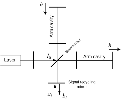
To measure the optical gain of the interferometer response to a strain , the end test masses are displaced differentially by application of an external sinusoidal force. Typically, the applied displacement is large, so that and the input vacuum is ignored. In that approximation, the ratio between and in Eq.(2.26) of Buonanno01b is the optical gain,
| (1) |
where is the output field with readout phase . and are defined as:
| (2) | |||||
| (3) |
In these equations, is the net phase gained by the laser light due to a sinusoidal GW with angular frequency in the arm cavity, is the half bandwidth of the arm cavity, is the power transmissivity of the arm cavity input mirrors, is the length of the arm cavity, is the amplitude transmissivity and is the amplitude reflectivity of the SR mirror, and is the detuning of the signal cavity from carrier resonance. is an effective coupling constant which relates the mirror motion to the output signal,
| (4) |
where is the input light power at the beamsplitter enhanced by the PR gain and is the light power needed by a conventional interferometer (with no signal cavity) to reach the SQL at sideband frequency . is the mass of each arm cavity mirror, and is the carrier angular frequency. in Eq.(1) is the SQL for gravitational wave strain measurement, given by . Again, quantum noise is neglected in this calculation of the predicted optical gain.
As mentioned above, the optical gain described by Eq. (1) exhibits a detuned RSE optical resonance peak and an optical spring peak. The shape of the optical gain as a function of frequency is somewhat different than the (inverse of the) shape of the quantum-limited sensitivity curve; owing to the assumption that , quantum noise correlations will not be evident when the optical gain is measured.
Several small-scale (“table-top”) experiments have been used to study optical configurations similar to that planned for Advanced LIGO, and developed prototypes for the control topology required to operate them Muller03 ; Mason03 ; Shaddock03 ; Miyakawa02 . The results of these experiments formed the basis for the Advanced LIGO design Strain03 . More recently, Somiya et al. Somiya05 developed and operated a detuned RSE interferometer with suspended mirrors. Optical springs have been observed in detuned single Fabry-Perot cavities with low input power (no power recycling) and light masses, by Sheard et al. Sheard04 and Corbitt et al. Corbitt05 . The parametric instability in high power stored cavities has also been explored Corbitt05 .
The Caltech 40 meter (40m) prototype interferometer was originally developed as a test bed for the initial LIGO optical configuration and control system, and currently it is used as a test bed for Advanced LIGO Weinstein02 ; Miyakawa04 . The optical configuration of the 40m (Fig. 2) is chosen to be similar to the optical configuration envisioned for Advanced LIGO. The arm cavities were chosen to have the same finesse as Advanced LIGO (around 1200); the input test mass mirrors (ITMs) have power transmission of 0.5%. The power recycling gain is designed to be 15, and a signal recycling cavity detuning is chosen to increase the detector bandwidth.
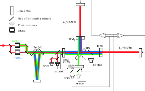
The light source is a 10 W continuous Nd:YAG laser which has a frequency stabilization servo, a pre-mode cleaner, and an intensity stabilization servo. Phase modulated RF sidebands are placed on the input beam at 33.2 MHz and 166.0 MHz using electro-optic modulators in a Mach-Zehnder interferometer. The light is attenuated, and 1 W is injected into a 13 meter mode cleaner (MC) which consists of 3 suspended mirrors forming a triangular cavity with 13 m half-length. This mode cleaner serves to further stabilize the laser frequency, while transmitting the carrier light an both pairs of RF sidebands. The beam passes through a Faraday isolator, reflective mode-matching telescope, and PZT-actuated mirrors which steer the beam into the main interferometer.
All ten core optics (three for the mode cleaner and seven for the main interferometer) are suspended as single pendula; they behave like free masses above the pendulum resonant frequency (around 0.8 Hz) and thus respond easily to the optical spring (the optomechanical rigidity is much larger than the mechanical rigidity of the mirror suspension). The suspended optics are placed on passive seismic isolation stacks, within a single vacuum volume. (In Advanced LIGO, multiple pendulum suspensions and active seismic isolation systems will be used).
The main interferometer has five degrees of freedom that require length control: the common and differential modes of the two Fabry-Perot arm cavities, the Michelson fringe, the PR cavity and the detuned SR cavity. Output beams are monitored with RF photodiodes, and length sensing signals are derived from demodulations at 33.2, 132.8, 166.0 and 199.2 MHz. Length control servos are implemented in a digital system to allow dynamical reconfiguration of the control topology and the signal filtering during and after lock acquisition. The typical control bandwidth of these servos is 300 Hz.
Because of the complexity of the optical configuration and the coupling of all the RF sidebands in the detuned signal cavity, lock acquisition and control of the interferometer is far more challenging than in Initial LIGO. Full lock acquisition and control in the desired configuration was first achieved in November 2005, through a process that will be described in a later publication. The buildup of carrier and RF sideband fields in the interferometer were then observed to be qualitatively as expected. Arm cavity losses were somewhat higher than expected, however. The achieved power recycling gain is about 5 and the arm cavity finesse is about 1200. The total power inside each arm is about 1.9 kW.
In order to measure the optical response of the interferometer to differential arm length changes (such as would arise in the presence of a gravitational wave), external sinusoidal forces are applied to the suspended optics at the ends of the arms via magnetic actuation, through the servo loop controlling that length degree of freedom. The error signal for that servo loop is extracted at the asymmetric port of the detector, after transmission through the signal cavity. The light is detected at the signal port, demodulated at 166 MHz, whitened, digitized, filtered, and then fed back to the differential displacement of the two suspended optics at the ends of the arm cavities.
The optical gain of the differential mode of the arms is measured as the spectral transfer function from the in-loop feedback signal to the error signal. This transfer function includes, in addition to the desired optical response, the actuator pendulum transfer function which has a behavior above the pendulum resonant frequency of 0.8 Hz. There are also known whitening and anti-aliasing filters, and time and phase delays associated with the conversion from analog to digital and from digital to analog. The delays are measured with another simpler optical configuration consisting of a single Fabry-Perot arm cavity, and compensated.
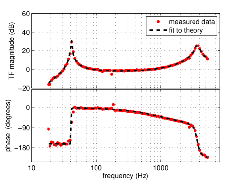
Fig 3 shows the measured optical gain (solid line) and the prediction from Eq. (1) (dashed line). In Fig 3, the peak at 41 Hz is due to the optical spring resonance and the peak at approximately 3600 Hz is due to the optical resonance of the signal sideband in the RSE signal cavity. Table 1 shows the parameters which are used to calculate the model of the optical gain for the differential mode of the arms.
| Quantity | Symbol & value |
|---|---|
| Power at beam splitter | W |
| Laser angular frequency | |
| End-mirror mass | kg |
| SR mirror transmissivity | (amplitude) |
| Laser power to reach SQL | kW |
| Arm cavity half bandwidth | |
| Arm cavity length | m |
| Input test mass transmissivity | (power) |
| SR cavity detuning | rad |
| Homodyne phase | rad |
Degeneracies of parameters which determine the optical response of the interferometer were investigated in Buonanno03 . Of particular note are equations (13) of Buonanno03 , which shows the relation between the ITM transmittance, the signal mirror reflectivity, and the signal cavity detuning phase in determining the free RSE optical resonant frequency and equation (49) which relates these quantities, along with the circulating power, to the ponderomotive rigidity (the optical spring peak). In producing Fig 3, we assume the ITM and signal mirror transmittance to be at their design values, and vary the detune phase, signal cavity losses, circulating laser power, and measurement quadrature to fit the theoretical curve to the measured data. The values thus obtained are consistent with our expectations based on the interferometer design, and on other measurements made with the interferometer.
The quadrature in Eq. (1) can be chosen by changing the RF demodulation phase of the 166 MHz local oscillator because the upper +166 MHz sideband is designed to be resonant in the combined signal and power cavities, while the lower -166 MHz sideband is not resonant there. This unbalanced RF sideband at the detection port makes it possible to choose the quadrature Somiya03 . In this measurement, is determined to be 0.22 rad by fitting the measured response in Fig 3.
The Michelson asymmetry combined with the detuned signal cavity causes the control RF sidebands to be imbalanced in the interferometer. This leads to demodulation phase dependent offsets in the error signals derived from these sidebands. These offsets are largely indistinguishable from actual length deviations, and are strongly mixed among the short degrees of freedom. A lack of secondary diagnostics to precisely determine the offset in the signal cavity length sensing means that the signal cavity detuning was not known, operationally, to a precision greater than a few percent. Thus, we treat the detuning here as a partially free parameter, and the exact detuning used to produce the theoretical curve in Fig 3 was determined through a fit to the data.
The frequency of the optical spring peak is a function of the input power, as can be verified by varying the power incident on the beam splitter, . We can vary this power at the laser source, or equivalently, we can offset the common mode of the arm cavities from full resonance. This method also introduces an optical spring effect in the common mode of the arms, which we observe to be in quantitative agreement with expectations. In this way, we measure the optical gain in the differential mode with several different values of , shown in Fig. 4. Both the magnitude and phase (not shown) of the optical gain follow the prediction from Eq. (1), with essentially no free parameters. In particular, the dependence of the quadrature on the offset of the common mode follows from a detailed numerical calculation.
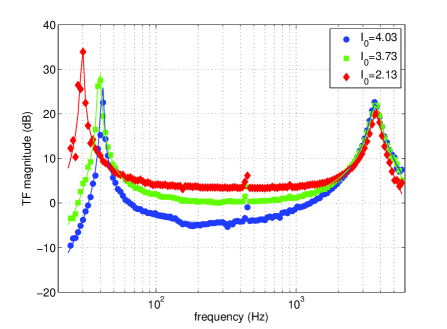
The form of the measured optical gain and its dependence on the effective laser power are in good agreement with the prediction, thus building confidence in both the theory and practical implementation of the RSE interferometer’s response to differential displacement. In particular, the theoretical prediction for the quantum-limited sensitivity achievable by Advanced LIGO is supported. However, we do not report on the measured noise spectrum or its comparison with prediction in this paper. Other noise sources make it impossible at present to achieve quantum-limited sensitivity in the frequency range of interest for GW detection with the 40m interferometer.
Note that the 180∘ phase advance in the optical spring resonance results in an instability Buonanno02 , but in practice it was not a problem to acquire operational lock for this experiment because the control bandwidth was about 300 Hz, well above the optical spring resonance at 41 Hz. The servo unity gain frequency in this measurement lies between the optical spring resonance and the RSE optical resonance, in a region where the phase of the optical gain is fairly flat. This will probably not be the case in Advanced LIGO and other next-generation GW detectors, and the stability of the control servos must be carefully considered in the design.
This work is supported by the National Science Foundation cooperative agreement PHY0107417. This document has been assigned LIGO Laboratory document number LIGO-P060007-01-R. We thank the many members of the LIGO Laboratory, the LIGO Scientific Collaboration, and many valuable visitors to the 40 meter lab, for their invaluable contributions.
References
- (1) D. Sigg, Class. Quantum, Grav. 19, 1429 (2002).
- (2) F. Acernese et al, Class. Quantum, Grav. 19, 1421 (2002).
- (3) B. Willke et al, Class. Quantum, Grav. 19, 1377 (2002).
- (4) M. Ando and the TAMA Collaboration, Class. Quantum, Grav. 19, 1409 (2002).
- (5) E. Gustafson, D. Shoemaker, K. Strain, and R. Weiss, “LSC white paper on detector research and development,” LIGO Document Number T990080-00-D (1999).
- (6) “LIGO II conceptual project book,” LIGO Document Number L990267-00-M (1999).
- (7) A. Buonanno and Y. Chen, Class. Quantum, Grav. 18, L95 (2001).
- (8) A. Buonanno and Y. Chen, Phys. Rev. D 64, 042006 (2001).
- (9) A. Buonanno and Y. Chen, Phys. Rev. D 65, 042001 (2002).
- (10) V. B. Braginsky, Sov. Phys. JETP 26, 831 (1968).
- (11) B. J. Meers, Phys. Rev. D 38, 2317 (1988).
- (12) J. Mizuno, K. A. Strain, P. G. Nelson, J. M. Chen, R. Schilling, A. Rüdiger, W. Winkler, and K. Danzmann, Phys. Lett. A 175, 273 (1993).
- (13) K. A. Strain, G. Mueller, T. Delker, D. H. Reitze, D. B. Tanner, J. E. Mason, P. A. Willems, D. A. Shaddock, M. B. Gray, C. Mow-Lowry, and D. E. McClelland, Appl. Optics 42, 1244 (2003).
- (14) C. M. Caves and B. L. Schumaker, Phys. Rev. A 31, 3068 (1985).
- (15) B. L. Schumaker and C. M. Caves, Phys. Rev. A 31, 3093 (1985).
- (16) H. J. Kimble, Y. Levin, A. B. Matsko, K. S. Thorne, and S. P. Vyatchanin, Phys. Rev. D 65, 022002 (2002).
- (17) G. Müller, T. Delker, D. Tanner, and D. Reitze, Appl. Opt. 42, 1257 (2003).
- (18) J. Mason and P. Willems, Appl. Opt. 42 1269, (2003).
- (19) D. Shaddock, M. Gray, C. Mow-Lowry, and D. McClelland, Appl. Opt. 42 1283, (2003).
- (20) O. Miyakawa, K. Somiya, G. Heinzel, and S. Kawamura, Class. Quantum, Grav. 19 1555, (2002).
- (21) K. Somiya, P. Beyersdorf, K. Arai, S. Sato, S. Kawamura, O. Miyakawa, F. Kawazoe, S. Sakata, A. Sekido, and N. Mio, Appl. Opt. 44, 3179 (2005).
- (22) B.S. Sheard, M. B. Gray, C. M. Mow-Lowry, D. E. McClelland, and S. E. Whitcomb, Phys. Rev. A69, 051801(R) (2004).
- (23) T. Corbitt, D. Ottaway, E. Innerhofer, J. Pelc and N. Mavalvala, “Measurement of radiation-pressure-induced optomechanical dynamics in a suspended Fabry-Perot cavity” gr-qc/0511022.
- (24) A. Weinstein, Class. Quantum. Grav. 19, 1575 (2002).
- (25) O. Miyakawa et al., Proc. SPIE 5500, 92 (2004).
- (26) K. Somiya, Phys. Rev. D 67, 122001 (2003).
- (27) A. Buonanno and Y. Chen, Phys. Rev. D 67, 062002 (2003).