A squeezed state source using radiation-pressure-induced rigidity
Abstract
We propose an experiment to extract ponderomotive squeezing from an interferometer with high circulating power and low mass mirrors. In this interferometer, optical resonances of the arm cavities are detuned from the laser frequency, creating a mechanical rigidity that dramatically suppresses displacement noises. After taking into account imperfection of optical elements, laser noise, and other technical noise consistent with existing laser and optical technologies and typical laboratory environments, we expect the output light from the interferometer to have measurable squeezing of 5 dB, with a frequency-independent squeeze angle for frequencies below kHz. This squeeze source is well suited for injection into a gravitational-wave interferometer, leading to improved sensitivity from reduction in the quantum noise. Furthermore, this design provides an experimental test of quantum-limited radiation pressure effects, which have not previously been tested.
pacs:
04.80.Nn, 03.65.ta, 42.50.Dv, 95.55.YmI Introduction
Next-generation gravitational-wave (GW) interferometers, such as those planned for Advanced LIGO pfspie ; BC1 , are designed to have a fifteen-fold improvement in sensitivity over present-day detectors LIGOI . Advanced detector sensitivity at almost all frequencies in the detection band is expected to be limited by quantum noise Caves . At higher frequencies (above Hz for Advanced LIGO), quantum noise is dominated by shot noise, which reflects the accuracy at which test-mass motion is measured at individual instants; shot noise decreases with increased input laser power. At lower frequencies (below Hz), quantum noise is dominated by radiation-pressure noise, which arises from random forces exerted on the test masses by amplitude fluctuations of the light; radiation-pressure noise increases with increased laser power. At any given frequency, spectral density of the quantum noise is a sum of those of the shot noise, the radiation-pressure noise, and a term arising from their correlation. The Standard Quantum Limit (SQL) on precise measurement of the motion arises when the two noise sources are uncorrelated BK92 ; sql_def .
Since both types of quantum noise can be attributed to vacuum fields entering the interferometer from its anti-symmetric port Caves , injecting squeezed vacuum into this port can improve the sensitivity of the interferometer Caves ; Unruh . However, for different kinds of interferometers, the required squeezed vacuum may be very different. For example, for a Michelson interferometer with Fabry-Perot cavities in each arm that are tuned to the carrier frequency, and using a homodyne scheme to detect the phase quadrature of the output light (the quadrature in which the signal due to differential arm length changes resides), shot noise is associated with the phase quadrature of the input vacuum field, while radiation-pressure noise is associated with the input amplitude quadrature. As a consequence, a nearly phase-squeezed vacuum is required for higher frequencies, at which shot noise dominates; while a nearly amplitude-squeezed vacuum is required for lower frequencies, at which radiation-pressure noise dominates KLMTV . As another example, for a narrow-band signal-recycled configuration with homodyne detection, the squeezed quadrature of the input squeezed vacuum needs to go through a rapid change from below to above the optical resonant frequency in order for noise in the detected output quadrature to be suppressed (instead of amplified) throughout in this narrow frequency band harms . Moreover, speed meters have the property that their optimal squeezed quadrature stays fairly constant for a broad frequency band SM1 ; SM2 ; SM3 . Fortunately, it has been shown that detuned Fabry-Perot cavities can act as optical filters, which convert a squeezed vacuum with frequency-independent squeeze quadrature into one with frequency-dependent squeeze quadrature KLMTV , where is the sideband frequency SM2 . These filters have been shown to be broadly applicable to existing interferometer configurations KLMTV ; harms ; SM2 ; SM3 . Amplitude filters, which do not rotate the squeeze quadrature, but instead filter out (i.e., substitute with ordinary vacuum) the squeezed vacuum at above/below certain frequencies, have also been analyzed ampl_filt . With these filters as tools, it is sufficient to construct a device which generates frequency-independent squeezed vacuum.
The injection of squeezed light into the antisymmetric port of an interferometer has been experimentally demonstrated xiao_wu_kimble ; mckenzie2002 . In these experiments, the traditional method for preparing squeezed states of light using the nonlinearity in optical media was employed. The squeezed light was generated using optical parametric processes, and then injected into the antisymmetric port of the interferometer. The use of detuned Fabry-Perot filters in generating frequency-dependent squeezed quadratures also has been demonstrated recently chelkowski . In all of these experiments, sub-vacuum performance was measured in the few MHz frequency band, where the deleterious effects of classical noise sources, such as laser intensity and frequency noise, are greatly reduced. On the other hand, for GW detection, it is necessary to inject vacuum states that are squeezed in the GW band, from 10 Hz to 10 kHz. A recent experimental demonstration of squeezed vacuum at frequencies as low as 280 Hz mckenzie2004 has shown that low frequency squeezing is possible using optical parametric processes, but there may be technical limits to the level of squeezing that can be achieved by this technique, e.g., arising from photothermally driven fluctuations goda2005 .
An alternative technique is to extract the radiation-pressure-induced – or ponderomotive – squeezing generated inside an interferometer as a result of the coupling between the optical field and the mechanical motion of the mirrors. The properties of the ponderomotive squeezed state depend on the intensity of the laser light incident on the movable mirror, optical properties of the interferometer, and on mechanical properties of the mirror. In this paper, we propose and analyze a ponderomotive squeezing experiment, which is a variant of the interferometer that was analyzed in Ref. code_paper . The main features of this interferometer are high-power optical field and low-mass mirrors, suspended as pendulums, in order to enhance the radiation pressure forces; and the use of detuned Fabry-Perot arm cavities, which induces a optomechanical rigidity, or optical spring. Our proposal to use the optical spring effect is the major innovation over previous attempts to extract ponderomotive squeezing from interferometers kimble_private . With our high-power and low-mass system, the optical spring can be very stiff, and will shift the resonant frequency of the test mass from the suspension pendulum frequency of Hz up to kHz. There are two main consequences following this shift; for a sideband frequency between and : (i) all thermal and seismic forces will now induce much less motion of the mirror, with a reduction factor of , and (ii) since the mirrors response to driving forces is frequency independent at , the ponderomotive squeezing generated in this frequency band is frequency independent.
Experiments with the goal of directly measuring the SQL on the motion of macroscopic oscillators are similar to the experiment proposed here in that they must reach a sensitivity that is limited by quantum-limited radiation pressure. SQL experiments, however, rely on measuring at a quadrature where the radiation pressure noise and shot noise remain uncorrelated, whereas this experiment relies on measuring at a quadrature where the two noises are correlated. Furthermore, the optical spring in the ponderomotive squeezing experiment modifies the dynamics of the system, and allows squeezing to be observed without measuring at the level of the SQL, which greatly relaxes the sensitivity requirements compared to the SQL experiments.
The paper is organized as follows: In Sec. II we discuss the origin of ponderomotive squeezing using a single Fabry-Perot cavity as a simple but instructive case that explains many features of our experiment, and will guide our choice of parameters; in Sec. III we present and motivate the more complex design of the experiment; in Sec. IV we calculate contributions from expected noise sources; and in Sec. V we summarize our conclusions.
II Simplified consideration: an optical cavity
In this Section we consider the ideal case of a short, lossless Fabry-Perot cavity. For clarity and simplicity, we restrict ourselves to the quasistatic regime, in which the cavity bandwidth is much larger than the frequency of observation. This approximation provides quantitatively correct results in certain limited test cases.
Consider a Fabry-Perot (FP) cavity with a movable and perfectly reflective end mirror. Suppose laser light with frequency (the carrier) is incident on a fixed and highly reflective input mirror, and assuming the cavity to be close to resonance, we list several quantities characterizing the state of the cavity, namely its linewidth , finesse , circulating power , and the phase shift gained by the carrier as it comes out from the cavity, in terms of more basic parameters:
| (1) | |||||
| (2) | |||||
| (3) | |||||
| (4) |
Here is the cavity length, the input-mirror power transmissivity, the incident power, and the speed of light. The detuning parameter ,
| (5) |
is defined in terms of , the difference between the cavity’s (most nearby) resonant frequency and laser frequency. Note that in Eqs. (3) and (4), we have explicated the dependence of on and , and the dependence of on . Mathematically, our assumptions of highly reflective input mirror and the cavity’s closeness to resonance amounts to keeping results up to leading order in and .
The radiation-pressure, or ponderomotive, force acting on the end mirror is proportional to the optical power circulating in the cavity:
| (6) |
For a particular constant set of input power and detuning parameter , a DC force acting on the end mirror, e.g., from the pendulum, can balance the associated ponderomotive force and keep the mirror in mechanical equilibrium. Now suppose we shift the mirror statically, by , from this equilibrium condition. Because the detuning parameter will change, the ponderomotive force will also change, giving rise to an additional restoring force to that from the pendulum. The total restoring force can be written as (with the pendulum frequency and the end-mirror mass):
| (7) |
As we shall see later in this paper, the optical rigidity (or spring constant) that appears in this equation will be crucial for our ponderomotive squeezer. Note that Eq. (7) is valid not only for static changes in cavity length, but for all mirror motions band-limited well below the cavity linewidth — the quasistatic regime. It is also easy to obtain:
| (8) |
We are now ready to set up the frequency-domain equation of motion for the mirror, at non-zero frequencies well below the cavity linewidth (i.e., in the quasistatic regime):
| (9) |
In this equation, the ponderomotive force associated with AC power fluctuation and external forces have been considered. As for the output field, the AC component of the phase of the output carrier can be written as [Cf. Eqs. (4) and (8)]:
| (10) |
Here and henceforth this section, we shall use to denote DC components of the input power, detuning parameter, and carrier phase shift, and use to denote their AC components.
As can already be seen from Eqs. (9) and (10), any suspended cavity (not necessarily detuned) will convert input amplitude fluctuation into mirror motion, and subsequently output phase fluctuation — producing ponderomotive squeezing when the input fluctuations are quantum limited. Henceforth in this section, we shall further develop and apply these equations and study main features (in particular advantages) of a ponderomotive squeezer based on detuned cavities with optical rigidity. Before doing that, let us point out that in the case both mirrors are suspended, we can replace in the above formulas by the reduced mass
| (11) |
where and are the masses of the input and end mirrors of the cavity, respectively. [Throughout the manuscript we refer to the input and end mirrors of cavities as input mirror (IM) and end mirror (EM), respectively. ] We can do so because the cavity finesse is high, and the ponderomotive forces acting on the IM and EM are equal, with a value that only depends on their relative distance.
II.1 Input-output relation
Let us now put the above discussions, in particular Eqs. (9) and (10), into the two-photon formalism CS . The input field can be written as:
| (12) |
where is the mean amplitude and are quantum amplitude and phase fluctuations. It is convenient to normalize a coherent-state input wave as:
| (13) |
where , and are the single-sided spectral densities of and , and their cross spectral density, respectively. In the quasistatic regime, the entire output field will simply be phase-shifted from by , or
| (14) |
Decomposing into its DC () and AC () components, and treating as a small quantity, we obtain
| (15) |
with
| (16) |
where in the second line we have inserted Eq. (10).
So far we have essentially put Eq. (10) into the two photon formalism, let us now further develop Eq. (9). From Eqs. (7) and (3), we have
| (17) |
From this, we can further define a characteristic frequency,
| (18) | |||||
Note that can either be real () or be purely imaginary ().
On the other hand, the fluctuating part of the power incident on the cavity is
| (19) |
which induces a fluctuating force of
| (20) |
on the mirror [Cf. Eq. (9)]. Inserting Eqs. (17)–(20) into Eq. (9), we get
| (21) |
This means the mirror’s (complex) mechanical resonant frequencies will shift from to — if the latter lie within the quasistatic regime. Suppose this is true, and that is much lower than , then gives the mirror mechanical resonant frequencies. These could correspond either to a resonance in the usual sense when is real, or to a pure instability when is purely imaginary.
II.2 Quadrature coupling and squeezing
Assuming no external forces acting on the mirrors, we can put the frequency-domain input-output relation in a very simple form,
| (22) |
with a coupling constant
| (23) |
Clearly, couples the output amplitude and phase quadratures, and gives rise to squeezing in the output state.
In order to quantify squeezing, we look at the quadrature field measured by a homodyne detector, which is given by
| (24) |
where is the homodyne angle, with a convention in which corresponds to the simple amplitude detection of the output field. The fluctuating part of the output quadrature is
| (25) |
with a spectral density of
| (26) |
Note that for vacuum state we have .
By minimizing over quadratures, we obtain the amplitude squeeze factor
| (27) |
which is achieved at
| (28) |
In configurations considered here, the pendulum frequency is always much below and , and thus negligible. Now we can divide the value of into three regimes, if lies within the quasistatic regime (otherwise only the first regime exists). First, when , we have a constant of , which means we have a frequency independent squeezed state. The amplitude squeeze factor and squeeze angle of this state are:
| (29) |
| (30) |
Second, for , the coupling constant tends to zero and the output state becomes vacuum. Third, for , the system goes through a resonance, with strong squeezing and highly frequency-dependent squeeze angle, if is real, and goes through a smooth transition if is purely imaginary.111In reality, we must also consider the influence from a controller, which is necessary for stabilizing the detuned cavity, see Sections II.4 and IV.3.
Consequently, we obtain a frequency-independent ponderomotively squeezed source with squeeze factor (29) (which depends only on the detuning parameter ), and bandwidth . Although the squeeze factor can be lowered indefinitely by taking , the bandwidth will also drop in this process, according to Eq. (18) — unless input power and/or cavity finesse are increased.
As discussed in the introduction, such a squeezed state can be transformed into frequency dependent squeezed states by optical filters KLMTV ; SM2 ; harms ; ampl_filt ; chelkowski . Technically, the independence in frequency makes it easier to reduce laser noise, allowing broad-band squeezing, as we shall discuss in Section IV.4; it also simplifies our readout scheme.
II.3 Susceptibility to force noises
Let us now take into account the influence of noisy external forces [Cf. (21)]. For the same , if we denote the mirror’s response, in absence of optical rigidity, by , then the mirror’s response in presence of optical rigidity can be written as
| (31) |
which is suppressed by a factor , when . On the other hand, the transfer function from mirror motion to output optical field is not modified in any special way by the optical spring [Cf. Eq. (16)]. In the end, optical-field fluctuations caused by external forces on the mirror at the output port of an optical-spring system is suppressed by the same factor from a free-mass system with comparable circulating power, optical bandwidth, and external force disturbances.
This dramatic suppression, which applies to seismic noise and all thermal noises, can easily be as large as two orders of magnitude in amplitude, and is the most important reason for choosing an optical spring system as our candidate design for the ponderomotive squeezer. Theoretically, such a suppression is present even when a mechanical spring is used. However, mechanical springs introduce thermal noise, which are in general orders of magnitude higher than the vacuum noise associated with optical springs rigidity ; BC5 .
II.4 Radiation-pressure-driven instabilities
The quasistatic approximation we used in this section cannot describe the ponderomotive damping associated with optical rigidity. The sign of this damping is known to be opposite to that of the rigidity BC3 . In case we have a positive rigidity, the damping will then be negative, leading an oscillatory instability at the resonance frequency, , with a characteristic time
| (32) |
It can, therefore, be suppressed by a feedback system acting in restricted band , which is outside of our frequency band of interest . The control system for suppressing this instability is detailed in Section IV.3.
High circulating power in the detuned cavities, coupled with high quality factor () mechanical modes of the mirrors, may give rise another type of radiation-pressure induced instability MSUpla2001 . The motion of the mechanical modes of the mirror creates phase modulation of the intracavity field, which are converted into intensity modulation due to the detuning of the cavity. The intensity fluctuations, in turn, push back against the mechanical modes of the mirror. This mechanism forms an optical feedback loop that may become unstable in certain circumstances. In our case, the most likely form of instability is that in which the frequency of the mechanical mode is comparable to the cavity linewidth. This instability, which has been experimentally observed and characterized for the input mirror modes of our experiment pi_os , is well outside the bandwidth of our experiment, and stabilizing it with a narrowband velocity damping loop should be have little effect on the experiment. The modes of the end mirror are likely to be too high in frequency (compared to the cavity linewidth) to become unstable.
Radiation-pressure-induced torques can also lead to angular instability. Fabry-Perot cavities with suspended mirrors are susceptible to a dynamical tilt instability sidles_sigg : as the cavity mirrors tilt, the beam spots also walk away from the center of the mirrors, which induces a torque that drives the mirrors further away. This effect is considered in detail in Section III.1.
II.5 Optical losses
When a cavity with non-zero losses is considered, the noise spectrum at the quadrature becomes
| (33) |
where is the lossless noise spectrum of Eq. (26), and is the total loss per bounce in the cavity. Assuming that and , we have
| (34) |
III Experimental design
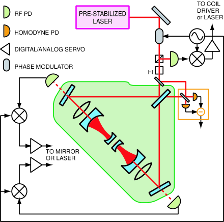
In this Section we describe the optical and mechanical design of a realistic experimental setup for the ponderomotive squeezer. The interferometer configuration shown in Fig. 1 is the baseline design for the experiment. The interferometer is similar to that used in GW detection: a Michelson interferometer with Fabry-Perot cavities in each arm. All the mirrors of the interferometer are suspended as pendulums. While squeezed light could be produced with the use of a single cavity and suspended mirror, as shown in Sec. II, the use of interferometry is necessary to introduce common mode rejection of the laser noise, which would otherwise mask the squeezed light. Moreover, dark fringe operation of the Michelson interferometer allows for keeping the dc power below photodetector saturation levels 222An alternative would be to use much lower input power and much higher finesse cavities, which is generally not feasible..
We consider the design features most critical to the goal of achieving measurable levels of squeezing. The optical design, described in Section III.1, includes:
-
•
A powerful input laser beam with stringent but achievable requirements on frequency and intensity stability to mitigate the effects of laser noise coupling;
-
•
A Michelson interferometer with good contrast for common-mode rejection of laser noise at the output;
-
•
Fabry-Perot cavities with
-
–
high finesse to realize the large optical power incident on the suspended mirror,
-
–
substantial detuning (comparable to the cavity linewidth) to create the optical spring,
-
–
a geometric design that mitigates the effects of radiation-pressure-induced angular instability;
-
–
-
•
An efficient readout chain to detect the squeezing.
The mechanical design of the mirror oscillator, also crucial to the performance of the interferometer, is described in Section III.2.
| Parameter | Symbol | Value | Units | Parameter | Symbol | Value | Units |
| Light wavelength | nm | Input mirror trans. | – | ||||
| Input mirror mass | kg | End mirror mass | g | ||||
| Arm cavity finesse | – | Loss per bounce | – | ||||
| Input power | W | Arm cavity detuning | rad/sec | ||||
| BS refl. imbalance | – | Mich. phase imbalance | |||||
| Mich. loss imbalance | Input mirror mismatch | – | |||||
| Detuning mismatch | Arm cavity loss mismatch | – | |||||
| Laser intensity noise | – | Hz-1/2 | Laser phase noise | – | – | ||
| Susp. resonant freq. | Hz | Susp. mech. Q | – | ||||
| Parallel coating loss angle | Perpendicular coating loss angle | ||||||
| Substrate Young’s modulus | N m-2 | Coating Young’s modulus | N m-2 | ||||
| Coating thickness | Beam radius | mm | |||||
| Detection loss | 0.1 | Temperature | K |
III.1 Optical design
The optical configuration is shown in Fig. 1, and upper section of Table 1 lists the optical parameters that we assume in designing the experiment.
III.1.1 Detuned arm cavities
The optical spring is the predominant feature of the detuned arm cavity — which has been analyzed in detail in Sec. II. In particular, when a cavity is detuned, the optical spring modifies the response function of the differential mode from a free mass (here we ignore the pendulum frequency) to a harmonic oscillator with resonant frequency [see Eq. (18)]. Our frequency band of interest is , in which the response of cavity lengths to external disturbances (e.g., driven by seismic and/or thermal forces) is suppressed by , and the (ideal) output state is a frequency-independent squeezed vacuum with squeeze factor as a function of [Eq. (29)]. Based on this qualitative understanding, in order to obtain a substantial squeeze factor up to around 1 kHz, we need to choose an optical configuration such that is at least several kHz, and of the same order of magnitude as . This lead us to a high-power, low-mass, substantially detuned arm cavity.
We have chosen to realize our optical-spring squeezer by a Michelson interferometer with Fabry-Perot cavities formed by a large, suspended mirror as the input mirror (IM), and a small, light, highly reflective mirror as the end mirror (EM). The EM is chosen to be g, as light as we deem possible with current experimental techniques. We note that the optical spring could also be created with a detuned signal recycling mirror, as is done in Advanced LIGO BC1 , but that would require an additional mirror and optical cavity, increasing the complexity of the system. The suspensions are primarily necessary to allow the mirrors to behave as free masses in the experimental frequency band, but also have the added benefit of isolation from seismic noise. To achieve these benefits, a pendulum resonant frequency of Hz is chosen. The arm cavities must be placed in vacuum chambers due to the high finesse and circulating power, and also to meet the length stability requirements. The mechanical design of the suspension of the end mirror is discussed in the next section.
Next we discuss the optical parameters of system. We first set an “ideal” target squeeze factor of 17 dB, i.e., the squeeze factor of the system in absence of optical losses and technical noises. This allows for the contribution of the vacuum fluctuations from the anti-symmetric port to the total noise to be small. This determines . As a next step, we fix the finesse of the arm cavity, which should be high because we would like to have the optical-spring resonance as high as possible, for a better noise suppression. Although this could be achieved by increasing input power alone, it is much more efficient to increase the finesse, because , see Eq. (18), note that we need to maintain for a fixed target squeeze factor); a higher input power is also undesirable because of the associated increase in amplitude and phase noise. On the other hand, cavities with too high a finesse will limit the output squeeze factor through increased optical losses, and will also increase the instability from the optical spring. In the end, we set the transmission of the input mirror to be ppm, which, if assumed to be the dominant loss in the cavity, gives a finesse of . In this system, for a 4 W input laser power, we have a circulating power of roughly 9 kW, and kHz.
III.1.2 Angular instability
Our discussion of the optical properties of the cavities so far has been restricted to the longitudinal resonances. In this section we consider the geometrical properties of the cavity, necessary to avoid angular instability due to radiation-pressure-induced torque sidles_sigg . For a cavity with two spherical mirrors, the equations of motion of the two mirrors are rather straightforward, if the motion frequency is much lower than the cavity bandwidth (which is trivially true in our case). Suppose are the tilt angles of two mirrors with radii of curvature , separated by , then the equations of motion of are given by (here and henceforth we denote IM by and EM by )
| (35) |
with
| (36) |
Here are the resonant frequencies of the tilt degrees of freedom of the mirrors in the absence of radiation pressure,333We consider two types of tilt angles, pitch and yaw, described in Section III.2 for our mirrors. In the ideal situation, pitch and yaw are orthogonal degrees of freedom and can be considered separately. The resonant frequencies of the IMs and EMs when they are “free” masses, , will, however, differ from each other, as will the pitch and yaw mode frequencies for each optic. and are the -factors, defined by
| (37) |
The angular frequencies are given by
| (38) |
where are the moments of inertia of each mirror along the tilt axis under consideration. These frequencies set the time scales of tilt-induced dynamics associated with each mirror. In Table 2, we list the relevant parameters for our IM and EM, along with the resulting . Note that does seem to be in a regime (a few Hz) where we have to worry about tile instability. As pointed out by Sidles and Sigg sidles_sigg , in the absence of external restoring forces, (i.e., as ), we have
| (39) |
which means always has one positive eigenvalue (pure instability) and one negative eigenvalue (stable resonant mode). On the other hand, the terms, if large enough, will stabilize the system.
| k | (cm) | (cm) | (g) | (g) | (Hz) |
|---|---|---|---|---|---|
| kW | |||||
| IM | 4.25 | 2.00 | 250 | 1211 | |
| EM | 0.60 | 0.30 | 1.00 | 0.098 |
Let us first examine the case without external restoring force. The resonant frequencies are in general given by
| (40) | |||||
Noticing that we have , we can expand the unstable resonant frequency up to the leading order in . We also have to require that is not very close to (). Now if we pay attention only to , which is the unstable resonant frequency, then we have
| (41) |
This confirms, in our special case, that cavities with negative factors are less unstable, as argued by Sidles and Sigg sidles_sigg . Moreover, each mirror itself, when the other mirror is held fixed, is stable in the case of negative -factors (since diagonal elements in are both negative).
Now let us study the stability when external restoring forces are available. In general the resonant frequencies are given by
| (42) |
The stability condition can be stated more formally as having negative definite, which means requiring
| (43) | |||||
| (44) | |||||
| (45) |
with
For negative -factor cavities, which start out to be less unstable, the stabilization is easy: Eqs. (43) and (44) are automatically satisfied (since the diagonal elements are already negative in absence of external restoring force), while Eq. (LABEL:detMcond) can be satisfied without requiring any EM external stabilization, if
| (47) |
Stabilization is less straightforward for positive -factor cavities: will have to be at least of the same order as , unless we fine-tune . For example, Eqs. (43) and (44) already impose
| (48) |
which suggests that will have to be at least comparable to , unless we make very small, which is undesirable due to decreased stability of spatial optical modes. Defining
| (49) |
the stability condition can be written as
| (50) |
For stability reasons, we propose using negative -factor cavities. To minimize the angular instability and simultaneously maximize the beam spot size at the mirrors in order to reduce the effects of the coating thermal noise, as discussed in Section IV.2, we propose cavities of length m, with the mirrors having a radius of curvature slightly greater than m, in order to have .
From Eq. (47), we find a stabilizing IM frequency of Hz, which is trivially satisfied, to be sufficient to stabilize the system without an active control system.
III.1.3 Optical readout
Ideally, the squeezed field would be measured at the antisymmetric port with a homodyne detector. In this setup, a strong local oscillator (LO) field is mixed on a beamsplitter with the squeezed field, and the two resulting fields are measured by photodiodes and the resulting photocurrents are subtracted, eliminating the component of the signal due to the LO alone. This scheme is advantageous because it allows for an arbitrary quadrature of the squeezed field to be measured, simply by changing the phase of the LO. The disadvantage of this scheme, however, is that the LO field must be much stronger than the carrier component of the squeezed field. Due to mismatches in the system, a portion of the carrier light will couple out the antisymmetric port. With the parameters for contrast defect and other optical imperfection listed in Table 1, we expect the carrier light at the output to be on the order of . While a LO level that is an order of magnitude larger is readily achievable, we begin to reach the saturation limits of our photodetectors.
An alternative readout scheme is to simply measure the squeezed field with a photodetector. In this scheme, only the amplitude fluctuations of the light exiting the antisymmetric port may be measured. However, our optimization scheme for laser noise, as described in Sec IV.4, has the side effect of aligning the squeezed quadrature with the amplitude quadrature of the light exiting the antisymmetric port. While this limits us to measuring only the amplitude fluctuations of the light, this is precisely the quadrature in which the squeezing occurs. The homodyne readout scheme is preferable, but the direct readout is a viable alternative to avoid power constraints.
In practice, since we wish to control the interferometer degrees of freedom, we use the detection scheme shown in Fig. 4. A small fraction of the antisymmetric port light ( in power) is sampled to generate an error signal for the control loop, while the majority is preserved for injection into an interferometer or for detection of squeezing using either the homodyne or direct detection methods described above.
III.2 Mechanical design
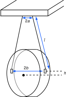
Both the input and end mirrors of the cavities are suspended from pendulums. The input mirrors have a mass of 250 g and a 75 mm diameter; they are identical to the suspended optics used in the input modecleaner of the initial LIGO detectors s1_detector . Greater care must be taken in the suspension of the end mirrors of the cavities, however – due to their small mass of g, the EMs have greater susceptibility to thermal noise. We use a monolithic fused silica suspension, in which thin fused silica fibers are welded to the side of the mirror substrate using a laser. This technique has been demonstrated to produce a pendulum mode Q of approximately freytsis . The suspension design consists of two fibers, each approximately in diameter, welded or glued to the mirror, as shown in Fig. 2.
To maintain high circulating power in the arm cavities, and minimize interference from higher-order spatial modes, alignment of the mirror is critical. Controlling the pitch (rotation about the horizontal diameter of the mirror) is a particularly important consideration, since we expect large pitch angles due to static displacement of the EM with 9 kW of laser power impinging on it. The frequency of the pitch mode is determined by the location of the attachment point between the fiber and the mirror substrate, and the diameter of the fiber gonzalez . For our regime of fiber lengths, typically 0.5 m, the frequency of the pitch mode frequency, is approximately
| (51) |
assuming , where is the characteristic length at which the fiber bends above its attachment point, is the distance of the attachment point from the mirror center of mass, is the length of the suspension wire, is the tension in the fiber, and is the moment of inertia for the pitch degree of freedom (given in Table 2). A higher frequency, , will require a larger force to control the pitch of the mirror. Minimizing the necessary force, and hence is desirable to limit the actuator range. For fibers with a diameter of , mm, while for , mm. In the case, it would be impossible to make smaller than a few millimeters, while for the case, it can be made very small by choosing appropriately. Consideration of the necessary torques that must be supplied, and the torques that may be generated by actuators, as well as the ability to create and work with thin fibers, leads to a choice of fiber diameter of approximately . Taking , , dyne, we get Hz. The yaw frequency, again assuming that , is
| (52) |
where is the separation between attachment points of the fibers at the top end of the suspension, is the distance between the attachment points on either side of the mirror, and is the moment of inertia for the yaw degree of freedom. For , , , we get Hz.
Control of the longitudinal motion of the end mirror is a difficult task. When the kW of power in the cavity is incident on the end mirror, the mirror feels a constant force, which must be balanced. We choose to balance the constant (dc) radiation pressure force with gravity. When the mirror is displaced by a few millimeters from its equilibrium (with no laser light present), for a given (fixed) pendulum length, the gravitational restoring force will be equal to the constant radiation pressure force. In order to lock the cavity at full power, we propose the following scheme: First, we use an electromagnetic actuator to offset the mirror the required distance from its equilibrium position. Next, we lock the cavities with very small circulating powers, such that the radiation pressure forces are negligible. We slowly increase the power in the system, which increases the radiation pressure forces on the mirrors. Simultaneously, we reduce the pulling force of the actuator, which will be counteracted by the increasing radiation pressure force, keeping the mirror at a fixed position. When the power reaches its design value, the mirror is held in place by a balance of the radiation pressure, gravitational restoring, and electromagnetic forces. This provides a way of controlling the longitudinal degree of freedom of the mirror.
IV Noise Couplings
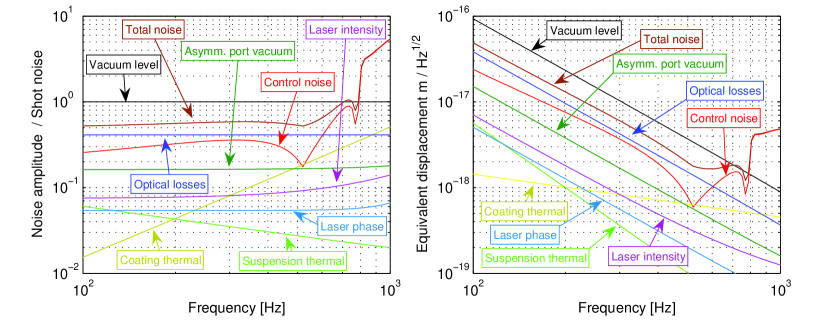
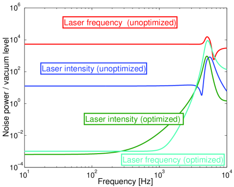
In this section, we estimate the contribution of expected noise sources to the total noise budget. These include thermal noise from the suspended mirrors (including thermal noise from the optical coatings on the substrates), as well as laser intensity and phase noise. In Fig. 3, we show the spectral density of the dominant noise sources both in terms of noise power relative to the vacuum level in a given quadrature, and also in terms of (free mass) displacement, which does not include the suppression from the optical spring. Furthermore, we shall see that the coupling of laser noise has a very strong dependence on the quadrature to be measured. Careful choice of the measurement quadrature is critical to successful extraction of the squeezing; this is analyzed in Section IV.4.
IV.1 Suspension thermal noise
Applying the Fluctuation Dissipation Theorem fdiss to an object of mass that is suspended from a pendulum with mechanical quality factor and resonant frequency , we get the free mass displacement noise spectrum Saulson
| (53) |
where is the temperature and is the Boltzmann constant. The monolithic fused silica suspension, described in Section III.2, is used primarily to reduce . Metal wires and alternative methods of attachment have higher losses, which would make the suspension thermal noise more severe. As shown in the curve labelled “Suspension thermal” in Fig. 3, the monolithic fused silica suspension will place the suspension thermal noise at a level where it does not have any measurable effect on the experiment.
IV.2 Internal and coating thermal noise
The free mass displacement noise spectrum due to internal and coating thermal noise has been approximated as coatingnoise
| (54) |
IV.3 Control System Noise
As discussed in Section II.4, the optomechanical resonance is unstable, i.e., it grows in time, with typical time scale for instability given by Eq. (32). This instability must be controlled by use of a feedback loop that stabilizes the unstable resonance by a damping-like control force.
Defining , the transfer function of the pendulum, including the optical spring effect, is given by
| (55) |
This transfer function is straightforward to interpret; it is the transfer function of an ideal spring, with a spring constant that is filtered by the cavity pole. In the limiting case that and , the transfer function of an ideal pendulum is obtained. This transfer is unstable because it has poles in the right half plane (the real part of the pole is greater than ).
To stabilize this resonance, we apply a velocity damping force via a feedback control system; a schematic for the control system is shown in Fig. 4. Ordinarily, we are interested in the (squeezed) output field that exits the ponderomotive interferometer (IFO), but we need to detect a small fraction of to generate a control signal for damping the unstable resonance. We, therefore, insert a beamsplitter (BS) at the IFO output and use the field () in a feedback loop. The quadrature field is converted into a force by the transfer function and converts force to quadrature fields. The velocity damping term is included in . contains the force-to-displacement transfer function [see Eqn. (55)], as well as the input-output relation that converts displacement to quadrature field [see e.g. Eqns. (63) and (64) of Ref. code_paper ]. The majority of the squeezed field, , is preserved as a squeeze source. Vacuum noise fields , and enter the open ports of the beamsplitter, and must be accounted for in the total noise budget.
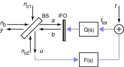
Defining the open-loop gain of the feedback system as
| (56) |
the squeezed output field y is given by
| (57) | |||||
where is a matrix operator that converts the input field a to the output b, converts forces into quadrature fields, and the subscript denotes the projection on the quadrature to be measured. Eqn. (57) warrants some discussion. The first term contains the squeezed output due to the input field a. In order to realize the squeezing without the influence of the control system, it is necessary to make as small as possible in the band where squeezing is to be measured. Similarly, when , the last term dominates and should be kept small to couple as little of the vacuum noise to the output .444We do not combine the last two terms containing because we will assume that those two terms are uncorrelated. This is not true, but will at worst give an underestimation by a factor of of the noise, and for the cases when , the error is much smaller. Finally, to stabilize the optomechanical resonance, we need to introduce a damping term to [implicitly included in ]. We propose a filter transfer function that is equivalent to applying a velocity damping:
| (58) |
where is a damping constant chosen to stabilize the system. The open loop gain then becomes
| (59) |
In addition to stabilizing the optomechanical resonance, we must minimize the additional noise due to vacuum fluctuations that are introduced by the new beamsplitter. We consider only the newly i8ntroduced vacuum noise that is detected by the feedback detector, which is then fed back onto the position of the pendulum and thereby enters the signal detected by the squeeze detector. We neglect the correlations between these vacuum fluctuations that enter directly at the beamsplitter with those that enter through the feedback loop. This is a valid assumption for frequencies at which , which is the case in our measurement band. Assuming that the feedback detection is shot-noise-limited, then the power spectral density of the additional noise, relative to shot noise, is
| (60) |
[see the last two terms in Eqn. (57), with so that ]. Choice of 3 to 10% for the nominal value of gives acceptable levels of loss for the squeezed output beam, while allowing for feedback. We note that for the case , that these expressions are not valid, and a detailed calculation of the correlations must be done. The correlation between the last two terms in Eqn. (57) depends on the quadrature being measured to do the feedback; we assume the worst case scenario for the noise, namely that the two terms add in amplitude.
In order to keep the coupling of vacuum noise into at a minimum, we must make the loop gain as small as possible at frequencies within the squeezing measurement band (about 100 Hz to 1 kHz), while still having sufficient gain at the optomechanical spring resonance frequency (typically 5 kHz). We achieve this by including a sharp high-pass filter in , typically an elliptic filter with high-pass corner frequency at a several 100 Hz to preserve phase margin at the optical spring resonance. The resulting contribution to the overall noise budget is show as the curve labeled “Control noise” in Fig. 3, where we set , , and a fourth-order elliptic high-pass filter with cut-off frequency at 800 Hz. A detailed analysis of the control system can be found in Ref. control_doc .
IV.4 Laser Noise
Laser intensity and frequency noise couple to the output port of the interferometer through imperfections and mismatch in the optical parameters of the interferometer. Analytic calculation of such noise couplings were carried out in Ref. code_paper . The calculations lead to complex formulae that, in our opinion, do not provide much insight into the couplings, except the following qualitative features. For frequencies much below and , and up to leading order of , and , phase and amplitude noises both emerge in single quadratures (as a result, there exist a phase-noise-free quadrature, and an amplitude-noise-free quadrature.) The phase noise does not drive mirror motion, and emerges at the output at an orthogonal quadrature to the carrier leaking out from that port (i.e., the carrier coincides with the phase-noise-free quadrature). The amplitude noise, on the other hand, drives mirror motion, and emerges in a quadrature neither along nor orthogonal to the carrier. Different types of mismatches direct laser amplitude and phase noises into different output quadratures. Up to linear order in mismatch, the output phase (amplitude) noise can be expressed in the quadrature representation as a sum of quadrature vectors, each arising from one type of mismatch.
In full numerical results, we did not observe phase-noise-free and amplitude-noise-free quadratures, but instead found output quadratures in which contributions from one of the two laser noises has a rather deep minimum. The minimum-phase-noise and minimum-amplitude-noise quadratures do not generically agree with each other, nor do they generically agree with the minimum-quantum-noise quadrature. However, we have discovered that it is possible, by intentionally introducing controlled mismatches, to modify the quadrature dependence of both of the output laser noises in such a way that both the minimum-phase-noise and minimum-amplitude-noise quadratures align with the minimum-quantum-noise quadrature. Such a procedure greatly reduces the importance of the laser noise, as long as the noise in the minimum noise quadrature is concerned. This is shown in Figs. 5 and 6, using our fiducial parameters in Table 1.
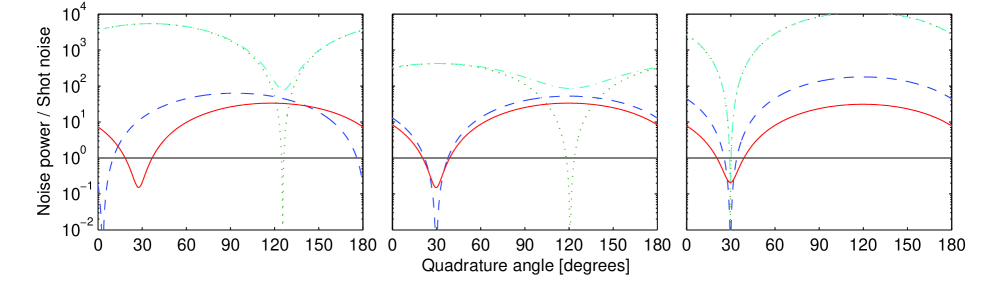
Let us describe the optimization procedure in more detail. Through the numerical simulation code_paper , we determine that the noise quadratures may be optimized through two steps, as shown in Fig. 6. The first step is to detune the Michelson from the dark fringe. The optimal position for the Michelson detuning is that which aligns the minimum-amplitude-noise quadrature to the minimum-quantum-noise quadrature. The second step is to introduce an intentional loss into one arm of the Michelson, placed artificially between the beamsplitter and one of the arm-cavity mirrors, such that both minimum-amplitude-noise and minimum-phase-noise quadratures would align with the minimum-quantum-noise quadrature. Interestingly, since the minimum-phase-noise quadrature coincides with the carrier quadrature leaking out from the output port, the resulting squeezed output light is amplitude squeezed.
As it turns out, the required artificial loss can be quite large; for our fiducial parameters in Table 1, the optimal loss is approximately 10%. Such a large loss will noticeably limit the amount of squeezing that may be detected, but the reduction in the laser noise is necessary to measure any squeezing at all. As shown in Figs. 5 and 6, the laser amplitude noise (as measured in the squeezed quadrature) is reduced by more than 40 dB and the laser frequency noise by more than 60 dB in this process — both of them now are far below the quantum noise level.
It is difficult to predict exactly the mismatches that will be present in the physical experiment. Rather than making a priori predictions for the intentional mismatch needed to optimize the noise couplings, we plan to perform this optimization empirically. We estimate that the ability to control the loss at the level of and the detuning at the level of is sufficient for the optimization.
Although we have greatly reduced the laser noise in the ideal quadrature, we have not reduced its overall magnitude. This presents a limitation because we must control the quadrature measurement angle to be precisely at the ideal quadrature. Small fluctuations in this measurement angle will couple noise in from the orthogonal quadrature, where the noise is much larger. This is evident from the sharp features in Fig. 6, which shows that the margin for error in the measurement quadrature is quite narrow due to the laser frequency noise.
IV.5 Quantum noise and losses
The quantum noise, due to output port vacuum fluctuations and optical losses, are also calculated using the noise simulation code code_paper . Considering only the noise that enters through the output port, and neglecting other noise sources, including optical losses, the vacuum field is squeezed by dB inside the interferometer.
Next, we include optical losses at the levels given in Table 1. In particular, our simulation code has automatically taken into account intracavity losses, losses due to transmission through the IMs, losses of the beamsplitter, losses into the common mode due to mismatches, and artificial losses introduced to mitigate laser noise in the detected quadrature. These together lead to a noise spectrum at the level of dB below shot noise (see Fig. 3). We expect this to be the limit to measurable squeezing in most of our frequency band.
IV.6 Summary of design considerations
Considerations of the detailed parameters of the experiment is a sequence of trade-offs between achieving high levels of squeezing and keeping the noise couplings to a minimum. In Table 3 we summarize the highly intertwined and often conflicting considerations that informed the design in the preceding sections.
| Parameter | Advantages of large value | Advantages of small value |
|---|---|---|
| ETM mass | Ease of construction | Large optical spring frequency |
| Ability to sense and actuate motion | ||
| ITM transmission | Large optical spring frequency | Reduce optical spring instability |
| (Cavity finesse) | Reduce effective intracavity losses | |
| Higher circulating power could damage mirrors | ||
| ITM mass | Ease of construction | Increase optical spring frequency 555Making the ITM mass the same as that of the ETM, for example, would increase the optical spring resonance frequency by . |
| Work with existing sizes and solutions | ||
| Input power | Large optical spring frequency | Use available lasers |
| Stay below damage threshold of cavity mirrors | ||
| Detuning or | Optimize for largest | Use smaller to increase squeezing level |
| squeezing bandwidth | ||
| Spot size on ETM | Reduce coating thermal noise | Reduce angular instability of cavity |
| Cavity length | For fixed beam size on mirror surfaces, | Reduce instability of optomechanical resonance |
| longer length increases suppression of | ||
| higher order spatial modes | ||
| Larger mirror radii of curvature easier | ||
| to manufacture |
V Summary and Conclusions
We have presented a design for an interferometer with movable light mirror oscillators, such that the light (and vacuum) fields circulating in the interferometer are squeezed due to the coupling of radiation pressure and motion of the mirrors. We show that even in the presence of reasonable, experimentally realizable optical losses (at the level of per bounce per optic), thermal noise (associated with oscillators with intrinsic loss factors of order ), and classical laser noise (relative intensity noise at the level of and frequency noise ), significant levels of squeezing can be extracted from such a device. Specifically, we find that as much as 7 dB of squeezing at 100 Hz is possible, provided great care is exerted to measure the quadrature where the laser noise coupling to the output is minimized, as shown in Fig. 3. We note that the squeezed state produced by this device will be far from a minimum uncertainty state (the noise in the anti-squeezed quadrature relative to the squeezed quadrature is much greater than required by Heisenberg’s Uncertainty Principle). This will place requirements on the stability requirements for any device to which the state is applied.
Two aspects of the design require great care: the optical performance of the high finesse, detuned arm cavities (described in Section III.1); and the mechanical design of the suspended 1 gram mirror oscillators, where thermal noise must be kept at low, and pitch, yaw and longitudinal degrees of freedom must be controllable by application of external forces outside the measurement band (described in Section III.2).
This is, to our knowledge, the first viable design for extracting the squeezing generated by radiation-pressure-induced rigidity in an interferometer, and construction of this experiment is underway at our laboratory.
Acknowledgements.
We thank our colleagues in the LIGO Scientific Collaboration, especially Vladimir Braginsky, Keisuke Goda, Eugeniy Mikhailov and Gregg Harry, for stimulating discussions. We gratefully acknowledge support from National Science Foundation grants PHY-0107417, PHY-0300345, PHY-0099568 (for Y.C.), and PHY-0353775 (for F.K. and S.V.). Y.C.’s research was also supported by the David and Barbara Groce Fund at the San Diego Foundation, as well as the Alexander von Humboldt Foundation’s Sofja Kovalevskaja Award (funded by the German Federal Ministry of Education and Research). F.K. and S.V.’s research was also supported by the Russian Agency of Industry and Science contracts #40.02.1.1.1.1137 and #40.700.12.0086, and by Russian Foundation of Basic Researches grant #03-02-16975-a.References
- (1) P. Fritschel, Proc. SPIE 4856-39, 282 (2002).
- (2) A. Buonanno and Y. Chen, Phys. Rev. D 64, 042006 (2001).
- (3) B. Barish and R. Weiss, Phys. Today 52, 44 (1999).
- (4) C. M. Caves, Phys. Rev. D 23, 1693 (1981).
- (5) V. B. Braginsky and F. Ya. Khalili, Quantum measurement, (Cambridge University Press, Cambridge, 1992).
- (6) V. B. Braginsky and F. Ya. Khalili, Rev. Mod. Phys. 68, 1 (1996).
- (7) W. G. Unruh, in Quantum Optics, Experimental Gravitation, and Measurement Theory, eds. P. Meystre and M. O. Scully (Plenum, 1982), p. 647;
- (8) J.H. Kimble, Y. Levin, A.B. Matsko, K.S. Thorne, and S.P. Vyatchanin, Phys. Rev. D 65, 022002 (2002).
- (9) J. Harms, R. Schnabel, and K. Danzmann, Phys. Rev. D 70, 102001 (2004) .
- (10) V. B. Braginsky and F. Ya. Khalili, Phys. Lett. A 147, 251 (1990); V. B. Braginsky, M. L. Gorodetsky, F. Ya. Khalili, and K. S. Thorne, Phys. Rev. D 61, 044002 (2000); P. Purdue, Phys. Rev. D 66 022001 (2002);
- (11) P. Purdue and Y. Chen, Phys. Rev. D 66 122004, (2002).
- (12) Y. Chen, Phys. Rev. D 67 122004 (2003) .
- (13) T. Corbitt, N. Mavalvala, S. Whitcomb, Phys. Rev. D 70, 022002 (2004).
- (14) M. Xiao, L.-A. Wu, H. J. Kimble, Phys. Rev. Lett. 59, 278 (1987).
- (15) K. McKenzie, D. A. Shaddock, D. E. McClelland, B. C. Buchler, and P. K. Lam, Phys. Rev. Lett. 88, 231102 (2002).
- (16) S. Chelkowski, H. Vahlbruch, B. Hage, A. Franzen, N. Lastzka, K. Danzmann, and R. Schnabel, Phys. Rev. A 71, 013806 (2005).
- (17) K. McKenzie, N. Grosse, W. P. Bowen, S. E. Whitcomb, M. B. Gray, D. E. McClelland, and P. K. Lam, Phys. Rev. Lett. 93, 161105 (2004).
- (18) K. Goda, K. McKenzie, E. Mikhailov, P. K. Lam, D. E. McClelland, and N. Mavalvala, Phys. Rev. A 72, 043819 (2005).
- (19) T. Corbitt, Y. Chen, and N. Mavalvala, Phys. Rev. A 72, 013818 (2005).
- (20) H. J. Kimble, private communication.
- (21) C. M. Caves and B. L. Schumaker, Phys. Rev. A 31, 3068 (1985); B. S. Schumaker and C. M. Caves, Phys. Rev. A 31, 3093 (1985).
- (22) A. Buonanno and Y. Chen, Phys. Rev. D 65 042001 (2002).
- (23) V. B. Braginsky, F. Ya. Khalili, Phys. Lett. A 257, 241 (1999).
- (24) A. Buonanno and Y. Chen, Phys. Rev. D 67, 062002 (2003).
- (25) V. B. Braginsky, S. E. Strigin, and S. P. Vyatchanin, Phys. Lett. A 287, 331 (2001).
- (26) T. Corbitt, D. Ottaway, E. Innerhofer, J. Pelc, and N. Mavalvala “Measurement of radiation-pressure-induced optomechanical dynamics in a suspended Fabry-Perot cavity,” submitted to Phys. Rev. Lett. (2005).
- (27) J. Sidles and D. Sigg, “Optical torques in suspended Fabry-Perot cavities,” submitted to Phys. Lett. A (2004).
- (28) B. Abbott et al. (LIGO Scientific Collaboration), Nucl. Instrum. Meth. A517, 154 (2004).
- (29) M. Freytsis, T. Corbitt, D. Ottaway, G. Harry, and N. Mavalvala, “Intrinsic mechanical loss of laser-welded fused silica fibers,” submitted to Rev. Sci. Instr. (2005).
- (30) G. González, Class. Quant. Grav. 17, 4409 (2000).
- (31) H. B. Callen and R. F. Greene, Phys. Rev. 86 703 (1952).
- (32) P. R. Saulson, Phys. Rev. D 42, 2437 (1990).
- (33) G. M. Harry, A. M. Gretarsson, P. R. Saulson, S. E. Kittelberger, S. D. Penn, W. J. Startin, S. Rowan, M. M. Fejer, D. R. M. Crooks, G. Cagnoli, J. Hough, and N. Nakagawa, Class. Quantum Grav. 19, 897 (2002).
- (34) T. Corbitt, Y. Chen, D. Ottaway, and N. Mavalvala, “Control system for damping the unstable optomechanical resonance in the ponderomotive interferometer,” LIGO Technical Document, LIGO-T050140-00-R (2005).