Also at: ]Space Radiation Laboratory, California Institute of Technology, Pasadena, CA 91125
Data Combinations Accounting for LISA Spacecraft Motion
Abstract
LISA is an array of three spacecraft in an approximately equilateral triangle configuration which will be used as a low-frequency gravitational wave detector. We present here new generalizations of the Michelson- and Sagnac-type time-delay interferometry data combinations. These combinations cancel laser phase noise in the presence of different up and down propagation delays in each arm of the array, and slowly varying systematic motion of the spacecraft. The gravitational wave sensitivities of these generalized combinations are the same as previously computed for the stationary cases, although the combinations are now more complicated. We introduce a diagrammatic representation to illustrate that these combinations are actually synthesized equal-arm interferometers.
pacs:
04.80.Nn, 95.55.Ym, and 07.60.LyThe Laser Interferometer Space Antenna (LISA) 1 is a space-borne gravitational wave (GW) detector mission which will use coherent laser beams exchanged between three widely separated spacecraft to study low-frequency ( Hz) GWs. Modeling each spacecraft as carrying lasers, beam splitters, photo-detectors and drag-free proof masses on each of two optical benches, it has been shown 5 ; 6 ; 7 that the six measured time series of Doppler shifts of the one-way laser beams between spacecraft pairs, and the six measured shifts between adjacent optical benches on each spacecraft, can be combined, with suitable time delays, to cancel the otherwise overwhelming phase noise of the lasers () to a strain level . This technique is called time-delay interferometry (TDI).
Initial analyses of TDI 5 ; 6 ; 7 ; 9 ; 9aa were for a non-rotating, rigid LISA array. However,the actual LISA orbits 9a ; 9b produce annual rotation of the array. Recently, TDI applied to a rotating LISA was considered 10 . It was shown that the Sagnac effect leads to non-negligible light-time differences for light traveling around the array in the clockwise and counterclockwise senses. New candidate implementations of TDI involving both one-way measurements and laser phase-locking were presented which obviate the difficulties of a rotating array. In parallel work, Cornish and Hellings 1a pointed out that in addition to the rigid body rotation, more general inter-spacecraft velocities can occur (so called “flexing” of the LISA constellation). It was shown that this flexing will introduce phase noise at an unacceptable level, given the present laser frequency noise specification.
In this paper we first generalize the original Michelson TDI combinations to an array with systematic spacecraft velocities, showing that these generalizations effectively cancel all laser phase noises (residuals second order in v/c, much smaller than the secondary LISA noise levels). We then analyze the generalized Sagnac combinations, showing that they too cancel laser phase noise adequately in a rotating and/or shearing LISA array. Finally, we emphasize that the gravitational wave sensitivities of these generalized combinations are the same as those for the non-rotating case.
There are six beams exhanged between the LISA spacecraft, together with the six phase measurements () recorded when each transmitted beam is mixed with the laser light of the receiving optical bench. The phase fluctuations from the six lasers, which need to be canceled, can be represented by six random processes , where is the phase of the laser in spacecraft on the optical bench facing spacecraft . In what follows we assume the center frequencies of the lasers are all the same.
Since the LISA triangular array has systematic motions, the two one-way light times between any spacecraft pair are not the same 10 . Delay times for travel between the spacecraft must now be accounted for depending on the sense of light propagation along each link when combining these data. As before, we label the arms with single numbers given by the opposite spacecraft; e.g., arm 2 (or ) is opposite spacecraft 2. We use primed delays to distinguish light-times taken in the counter-clockwise sense and unprimed delays for the clockwise light times. (Note that we have changed the data labeling conventions from that used in all previous papers by the last three authors. The subscript labeling of in this paper is that of 10 .) Explicitly: is the one-way phase shift measured at spacecraft 3, coming from spacecraft 2, along arm 1. The laser phase noise in is , where we take c = 1, so that is the light time in the direction from spacecraft 2 to spacecraft 3. Similarly, is the phase shift measured on arrival at spacecraft 2 along arm of a signal transmitted from spacecraft 3. The laser phase noise in is , where is the light time in the sense from 3 to 2 along arm . Due to the relative motion, in general. For the further delays used in the TDI combinations we use the same conventions, being careful to distinguish light travel along arms with primes or not, depending on the sense of the measurement. For example, our notation for delaying the time series by the clockwise light time in arm 1 would be while delaying by the counterclockwise light time in arm would be . As before, we denote six further data streams, (), as the intra-spacecraft metrology data used to monitor the motion of the two optical benches and the relative phase fluctuations of the two lasers on each of the three spacecraft.
Cornish and Hellings 1a have formulated TDI when the two delay times on each link, e.g. and are not only different (pure rotation) but also themselves functions of time. In the subscript notation for delays the order of the subscripts now becomes important for laser phase terms. The subscripts can no longer be permuted freely to show cancellation of laser noises in the TDI combinations and we will use a semicolon, instead of a comma, to emphasize this. (The other, secondary, noises in LISA are so much smaller, and the rotation and systematic velocities in LISA are so intrinsically small, that index permutation may still be done for them.) We will then go to first order expansions of the velocity, , dropping quadratic terms in and acceleration terms. This iterated time delay method, to first order in the velocity, is illustrated abstractly as follows. Given a function of time , time delay by is denoted with the standard comma notation:
| (1) |
We then impose a second time delay :
| (2) | |||||
A third time delay gives:
| (3) | |||||
and so on, recursively; each delay generates a correction proportional to its rate of change times the sum of all delays coming after it in the subscripts.
Consider a constant-length equal-arm interferometer with one-way readouts for relative phase not only at the (central) spacecraft 1, but also at outlying spacecraft 2, and 3, with . The phase data , , , can be combined to give the Michelson response
| (4) |
where we have purposely grouped the terms in square brackets to indicate that they provide the synthesized two-way phase data from each arm measured at the central spacecraft 9c . With these conditions, the laser phase noise is eliminated in . An impulsive GW (duration short compared with ) will appear four times in the laser-noise-free time series .
With the unequal arm-lengths of space based interferometers, the time series no longer cancels the laser phase fluctuations, leaving behind a remaining laser noise term that is proportional to the difference in the arm lengths to first order. In order to correct for this problem, it was shown in 5 that the two-way measurements entering into must be differenced, with suitable delays, to again eliminate laser noise. This gives the TDI combination 5 :
| (5) |
together with the analogous time series, and , centered on spacecraft and obtained from equation (5) by permutation of the indices. The response function of to a gravitational wave pulse has twice as many terms as does , and results in an “8 pulse” GW response.
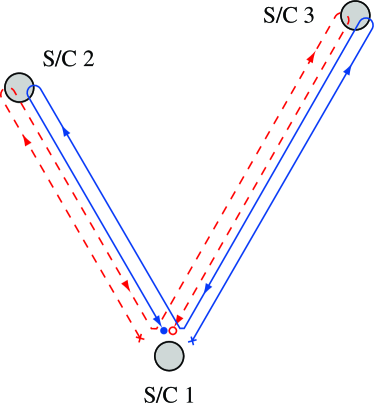
Equation (5) shows that is the difference of two sums of phase measurements, each corresponding to a specific light path (the continuous and dashed lines in Figure 1). The continuous line, corresponding to the first square-bracket term in equation (5), represents a light-beam transmitted from spacecraft 1 and made to bounce once at spacecraft 3 and 2 respectively. Since the other beam (dashed line) experiences the same overall delay as the first beam (although by bouncing off spacecraft 2 first and then spacecraft 3) when they are recombined they will cancel the laser phase fluctuations exactly, having both experienced the same total delays (assuming stationary spacecraft). For this reason the combination can be regarded as a synthesized (via TDI) zero-area Sagnac interferometer, with each beam experiencing a delay equal to . In reality there are only two beams in each arm (one in each direction) and the lines in Figure 1 represent the paths of phase information rather than paths of distinct light beams.
If LISA has pure rotation, so that , etc. are different but still time-independent, the original TDI combinations can be easily modified by being careful with the prime-noprime notation. This has been done in the above equations for X. In this case these modified TDI combinations still cancel all laser noises exactly 1a .
In the general case of time-dependent spacecraft separations, in which systematic velocities enter as a perturbation on the static LISA unequal arm configuration, it has recently been pointed out by Cornish and Hellings 1a that, for the LISA laser stability specifications of Hz/, the orbital variations, and , bring in laser phase noise in the combination at levels higher than the secondary noises in the lower part of the LISA frequency band ( Hz). The same effect also prevents perfect cancellation of the phase noise in the other stationary-spacecraft TDI combinations . Improving the laser noise performance by about one order of magnitude, and reducing the LISA arm lengths were suggested as possible solutions to recover the required LISA sensitivity. Technical challenges may make further frequency stabilization down to this level unfeasible. In the following we show that there is another solution that requires no modification of the LISA hardware: it is possible to generalize TDI combinations () to remove the velocity dependence of the laser noise term remaining in the combination. This is accomplished by further differencing the synthesized two-way measurements from each arm according to the diagram shown in Figure 2.
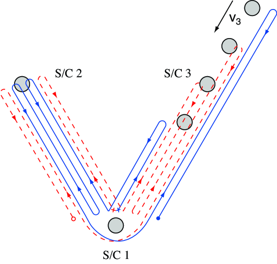
As an example, let us assume that the velocity of spacecraft relative to spacecraft and is as shown in Figure 2. In this configuration the effective optical paths of the two synthesized beams (continuous and dashed lines) can be described as follows. One of the beams (continuous line, for instance) is first made to bounce off spacecraft once, then spacecraft twice, and finally makes one more bounce off spacecraft before the phase measurement is made. Symmetrically, the other beam (dashed line) is first made to bounce off spacecraft once, then spacecraft twice, and once again off spacecraft before the phase measurement is made. By delaying the beams in this manner we are able to average out the changes of the arm lengths taking place over a round-trip-light-time, making the two optical paths of the two beams essentially equal.
The diagram shown in Figure 2 can be converted into a specific linear combination of the inter-spacecraft one-way phase measurements, , and metrology measurements performed onboard each spacecraft . This new TDI combination, , is very insensitive to “flexing”, and is given by:
| (6) | |||||
(with and obtained by cyclic permutation of the spacecraft indices.) Substituting into equation (6) the laser phase noise terms entering the and , and applying the expansion rules of equations (1 - 3), it can be shown that, to first order in the systematic relative velocities of the spacecraft, laser phase noise is once again eliminated. This degree of suppression puts the laser noises several orders of magnitude below the secondary noises, even for a rotating/shearing LISA array. Ultra-stable oscillator (USO) noises, which enter in the phase measurements of , can be calibrated and removed in the same manner as for 9 .
Note that if one were to implement the locking configuration described in 11 , in which one of the lasers in spacecraft is the master and the remaining five are slaved to it (so ), the expression above for would reduce to
| (7) | |||||
where the two data sets , should now be regarded as two-way measurements.
As with , the solution to “flexing” for the Sagnac combination can be obtained by analyzing the diagram shown in Figure 3. Consider the sequence of one-way measurements starting from spacecraft , and let us propagate counterclockwise and clockwise the (synthesized) beams, represented by the continuous and dashed lines in Figure 3.
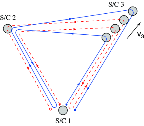
Once again, for this demonstration we have assumed spacecraft to have a non-zero velocity relative to the other two (stationary) spacecraft. The continuous and dashed lines correspond to the synthesized optical paths of the light transmitted by spacecraft . As Figure 3 suggests, this way of combining the one-way measurements compensates for the arm length imbalance generated by the motion of spacecraft during the round-trip time, making the delays experienced by the two synthesized beams essentially equal. By reference to Figure 3, the expression for the generalized Sagnac observable is:
| (8) | |||||
This expression coincides with that first derived in 10 except that now the order in which the delays are applied to the one-way measurements is important (as shown by the presence of a semicolon in equation (8)). Expanding this expression using the results of equations (1 - 3) we find that, unlike , the residual phase noise of the laser(s) at spacecraft 1 remains to first order in the systematic velocities. The residual phase noise in is:
| (9) |
Fortunately, although first order in the relative velocities, the residual is small, as it involves the difference of the clockwise and counterclockwise rates of change of the propagation delays on the same circuit. For LISA, the remaining laser phase noises in , , are several orders of magnitude below the secondary noises. LISA’s GW sensitivity in is essentially the same as for .
Since these generalized Michelson- and Sagnac-type TDI combinations involve twice as many terms as those entering into the original (stationary array) and modified (rotating array) TDI observables, the requirements in accuracies and precisions in physical quantities needed to synthesize the TDI combinations (such as arm length knowledge, synchronization of the onboard clocks, etc.) change. Our preliminary analysis indicates that the arm length and onboard clocks synchronization accuracies (needed to suppress laser noise to below secondary noise sources in these new TDI combinations) will be more stringent than those previously estimated for the original TDI combinations by a factor of about . Further analysis is needed on these requirements and on practical issues concerning the implementation of TDI for LISA.
This research was performed at the Jet Propulsion Laboratory, California Institute of Technology, under contract with the National Aeronautics and Space Administration.
References
- (1) P.L. Bender, K. Danzmann,& the LISA Study Team, Laser Interferometer Space Antenna for the Detection of Gravitational Waves, Pre-Phase A Report, (Max-Planck-Institüt für Quantenoptik, Garching), July 1998.
- (2) M. Tinto & J.W. Armstrong, Phys. Rev. D, 59, 102003 (1999).
- (3) J.W. Armstrong, F.B. Estabrook & M. Tinto, Ap. J., 527, 814 (1999)
- (4) F.B. Estabrook, M. Tinto & J.W. Armstrong, Phys. Rev. D, 62, 042002 (2000)
- (5) M. Tinto, F.B. Estabrook & J.W. Armstrong Phys. Rev. D, 65, 082003 (2002)
- (6) S. V.Dhurandhar, K. R. Nayak and J.-Y. Vinet Phys. Rev. D, 65, 102002 (2002)
- (7) M.A. Vincent & P.L. Bender, Proc. Astrodynamics Specialist Conference (Kalispell, Montana) 1 (San Diego: Univelt) 1346 (1987).
- (8) W.M. Folkner, F. Hechler, T.H. Sweetser, M.A. Vincent & P.L. Bender Class. Quantum Grav., 14, 1405 (1997).
- (9) D. A. Shaddock gr-qc/0306125v1 (2003), submitted to Phys. Rev. D.
- (10) N. J. Cornish & R. W. Hellings gr-qc/0306096v2 (2003)
- (11) M. Tinto, Phys. Rev. D, 58, 102001 (1998)
- (12) M. Tinto, D.A. Shaddock, J. Sylvestre, & J.W. Armstrong, Phys. Rev. D, 67, 122003 (2003)